CN102575574A - Wastegate arrangement for a turbomachine, turbine for an exhaust-gas turbocharger, exhaust-gas turbocharger, motor vehicle and method for operating an exhaust-gas turbocharger - Google Patents
Wastegate arrangement for a turbomachine, turbine for an exhaust-gas turbocharger, exhaust-gas turbocharger, motor vehicle and method for operating an exhaust-gas turbocharger Download PDFInfo
- Publication number
- CN102575574A CN102575574A CN2010800439659A CN201080043965A CN102575574A CN 102575574 A CN102575574 A CN 102575574A CN 2010800439659 A CN2010800439659 A CN 2010800439659A CN 201080043965 A CN201080043965 A CN 201080043965A CN 102575574 A CN102575574 A CN 102575574A
- Authority
- CN
- China
- Prior art keywords
- wastegate
- exhaust gas
- shaft
- lever arm
- force
- Prior art date
- Legal status (The legal status is an assumption and is not a legal conclusion. Google has not performed a legal analysis and makes no representation as to the accuracy of the status listed.)
- Granted
Links
Images





Classifications
-
- F—MECHANICAL ENGINEERING; LIGHTING; HEATING; WEAPONS; BLASTING
- F02—COMBUSTION ENGINES; HOT-GAS OR COMBUSTION-PRODUCT ENGINE PLANTS
- F02B—INTERNAL-COMBUSTION PISTON ENGINES; COMBUSTION ENGINES IN GENERAL
- F02B37/00—Engines characterised by provision of pumps driven at least for part of the time by exhaust
- F02B37/12—Control of the pumps
- F02B37/18—Control of the pumps by bypassing exhaust from the inlet to the outlet of turbine or to the atmosphere
- F02B37/183—Arrangements of bypass valves or actuators therefor
-
- F—MECHANICAL ENGINEERING; LIGHTING; HEATING; WEAPONS; BLASTING
- F02—COMBUSTION ENGINES; HOT-GAS OR COMBUSTION-PRODUCT ENGINE PLANTS
- F02B—INTERNAL-COMBUSTION PISTON ENGINES; COMBUSTION ENGINES IN GENERAL
- F02B37/00—Engines characterised by provision of pumps driven at least for part of the time by exhaust
- F02B37/12—Control of the pumps
- F02B37/18—Control of the pumps by bypassing exhaust from the inlet to the outlet of turbine or to the atmosphere
- F02B37/183—Arrangements of bypass valves or actuators therefor
- F02B37/186—Arrangements of actuators or linkage for bypass valves
-
- Y—GENERAL TAGGING OF NEW TECHNOLOGICAL DEVELOPMENTS; GENERAL TAGGING OF CROSS-SECTIONAL TECHNOLOGIES SPANNING OVER SEVERAL SECTIONS OF THE IPC; TECHNICAL SUBJECTS COVERED BY FORMER USPC CROSS-REFERENCE ART COLLECTIONS [XRACs] AND DIGESTS
- Y02—TECHNOLOGIES OR APPLICATIONS FOR MITIGATION OR ADAPTATION AGAINST CLIMATE CHANGE
- Y02T—CLIMATE CHANGE MITIGATION TECHNOLOGIES RELATED TO TRANSPORTATION
- Y02T10/00—Road transport of goods or passengers
- Y02T10/10—Internal combustion engine [ICE] based vehicles
- Y02T10/12—Improving ICE efficiencies
Landscapes
- Engineering & Computer Science (AREA)
- Chemical & Material Sciences (AREA)
- Combustion & Propulsion (AREA)
- Mechanical Engineering (AREA)
- General Engineering & Computer Science (AREA)
- Supercharger (AREA)
Abstract
Description
技术领域 technical field
本发明涉及用于涡轮机的废气门装置、用于废气涡轮增压机的涡轮机、废气涡轮增压机、机动车以及用于运行这种废气涡轮增压机的方法。 The invention relates to a wastegate arrangement for a turbomachine, a turbomachine for an exhaust-gas turbocharger, an exhaust-gas turbocharger, a motor vehicle and a method for operating such an exhaust-gas turbocharger.
背景技术 Background technique
文献DE 10 2004 041 166 A1描述了用于机动车的涡轮增压机的已知的结构,该涡轮增压机基本上由径向涡轮机以及布置在马达吸气侧中的径向压缩机组成,该径向压缩机通过涡轮增压机轴不可相对转动地与径向涡轮机的涡轮耦合。具有较高动能以及热能的废气流在运行中驱动涡轮,该涡轮通过与涡轮增压机轴的耦合使压缩机轮处于旋转中。径向压缩机吸入空气并且压缩空气,由此在发动机的吸气侧提供比在常规吸气发动机中相应更大量的新鲜空气并且因此提供更多的氧气。由此提高了发动机平均压力进而提高了发动机转矩,这引起了发动机的更高的功率输出。
为了调节流过涡轮机的废气量可以在涡轮增压机以及类似机构的涡轮机侧安装所谓的废气门阀门。废气门阀门是可控制的旁通阀。该旁通阀在调节在压缩机侧上的加载压力时引导一部分所产生的热废气在涡轮机旁通过直接导入排气管中。由此能够防止涡轮增压机过高的转速并且与之相联系地防止其支承的过载以及防止超过内燃机的机械极限以及热极限。 So-called wastegate valves can be installed on the turbine side of turbochargers and the like in order to regulate the amount of exhaust gas flowing through the turbine. The wastegate valve is a controllable bypass valve. The bypass valve guides a portion of the hot exhaust gas generated during the regulation of the acting pressure on the compressor side, bypassing the turbine and directly into the exhaust tract. This prevents an excessively high rotational speed of the turbocharger and, in connection therewith, overloading its bearings and exceeding the mechanical and thermal limits of the internal combustion engine.
例如借助于废气门活门控制流过废气门阀门的废气量。所述废气门活门例如不可相对转动地布置在可旋转地支承在涡轮机壳体中的废气门轴上,该废气门轴也称作废气门心轴。通过废气门轴的在操作杠杆上的线性运动借助于气动或者电动的执行器实现废气门活门的操作。该线性运动在废气门轴上产生转矩,由此能够打开以及关闭废气门阀门。 The quantity of exhaust gas flowing through the wastegate valve is controlled, for example, by means of a wastegate valve. The wastegate flap is arranged, for example, in a rotationally fixed manner on a wastegate shaft mounted rotatably in the turbine housing, which is also referred to as a wastegate spindle. The actuation of the wastegate flap takes place by means of a linear movement of the wastegate shaft on the actuating lever by means of a pneumatic or electric actuator. This linear motion creates torque on the wastegate shaft, thereby enabling opening and closing of the wastegate valve.
由于较高的废气温度,在涡轮机壳体中、通常在轴套中滑动支承着废气门心轴。因为轴套以及废气门心轴由于它们的不同的材料特性而具有不同的热膨胀系数,并且因为此外在废气涡轮增压机中必须覆盖很大的温度区域,所以轴套和废气门轴之间的滑动支承是有间隔的。由此,在这种摩擦副(Reibpartnern)之间没有平面的,而只有点状的接触。基本上产生了两个支承位置。一方面在滑动轴套的配属于涡轮机壳体的外侧的端部上、并且另一方面在滑动轴套的远离涡轮机壳体的外侧的端部上形成了支承位置。 Due to the high exhaust gas temperature, the wastegate spindle is slidably mounted in the turbine housing, usually in a bushing. Since the bushing and the wastegate spindle have different coefficients of thermal expansion due to their different material properties, and since a large temperature range must also be covered in the exhaust gas turbocharger, the distance between the bushing and the wastegate shaft is The sliding bearings are spaced. Consequently, there is no flat but only point-like contact between such friction partners. Basically, two bearing positions are produced. Bearing points are formed on the one hand at the end of the slide bush that is assigned to the outer side of the turbine housing and on the other hand at the end of the slide bush facing away from the outer side of the turbine housing.
不仅在打开废气门阀门时而且在关闭废气门阀门时,由杠杆臂的操作力以及由作用到废气门活门上的废气力产生的法向力作用在所述支承位置上。在关闭废气门阀门时所述法向力相互叠加并且引起滑动轴套中所产生的相对较高的法向力,这导致了支承位置中非常高的摩擦力矩。在打开废气门阀门时,用于操作杠杆臂的执行器必须以特定的力保持废气门阀门关闭,由此刚好由流过废气门阀门的废气压开所述废气门活门。为此所需的力虽然小于在关闭废气门阀门时所需的力,但是由操作力以及废气力产生的力沿着相同的力作用方向作用在支承位置中并且相互叠加。由此在打开废气门阀门时也在支承位置中产生了不可忽略的摩擦力矩。因为用于操作所述操作杠杆的执行器必须克服这种摩擦力矩,所以最大有待克服的摩擦力矩对于执行器的设计来说是决定性的。 The bearing point is acted upon by a normal force generated by the actuating force of the lever arm and by the exhaust gas force acting on the wastegate valve both when the wastegate valve is opened and when the wastegate valve is closed. When the wastegate valve is closed, the normal forces add to each other and lead to relatively high normal forces occurring in the sliding bush, which lead to very high frictional moments in the bearing position. When opening the wastegate valve, the actuator for actuating the lever arm must hold the wastegate valve closed with a certain force, so that the wastegate valve is just opened by the exhaust gas pressure flowing through the wastegate valve. Although the force required for this is lower than that required for closing the wastegate valve, the forces resulting from the actuating force and the exhaust gas force act in the same direction of force action in the bearing point and superimpose one another. This results in a non-negligible frictional moment even in the bearing position when the wastegate valve is opened. Since the actuator for actuating the actuating lever has to overcome this frictional moment, the maximum frictional moment to be overcome is decisive for the design of the actuator.
在应用以气动触发的废气门阀门时,至今为止几乎不考虑这一点并且有意地容忍以下缺点:例如由于执行器缺乏闭合力(Zuhaltekraft)而引起较大的泄漏流量并且因此在内燃机的较低转速范围内在全负载时涡轮增压机处于非最佳的工作方式。在用于触发废气门阀门的电动的执行器的第一系列应用中,为了克服较高的摩擦力矩使用非常强劲的电动的执行器。然而当执行器是冷的时这引起了非常大的力,从而会导致涡轮增压机的损坏。此外,使用强劲的并且因此也体积庞大的调节机构导致了较高的成本以及较大的结构空间需求。 When using pneumatically actuated wastegate valves, this has hitherto been hardly taken into consideration and the following disadvantages have been intentionally tolerated: e.g. higher leakage flows due to lack of closing force of the actuator and thus lower rotational speeds of the internal combustion engine The turbocharger operates in a sub-optimal manner at full load. In the first series of applications of electric actuators for actuating wastegate valves, very powerful electric actuators are used to overcome high frictional torques. However, this causes very high forces when the actuator is cold, which can lead to damage to the turbocharger. Furthermore, the use of a powerful and therefore also bulky adjusting mechanism leads to higher costs and a greater installation space requirement.
当然要避免这一点。 Of course avoid this.
发明内容 Contents of the invention
在所述背景下,本发明的任务在于提供一种用于涡轮机的改善的废气门装置。 Against this background, the object of the present invention is to provide an improved wastegate arrangement for a turbomachine.
该任务按本发明通过具有权利要求1所述特征的废气门装置和/或通过具有权利要求10所述特征的涡轮机和/或通过具有权利要求11所述特征的废气涡轮增压机和/或通过具有权利要求12所述特征的机动车和/或通过具有权利要求13所述特征的方法得到解决。
According to the invention, this task is achieved by a wastegate device having the features of
相应地提出: Correspondingly proposed:
一种用于涡轮机、尤其是用于废气涡轮增压机的废气门装置,其具有废气门阀门、带有第一支承位置和第二支承位置的废气门轴、不可相对转动地安装在废气门轴上的杠杆臂以及不可相对转动地安装在废气门轴上的废气门活门,其中如此构造所述废气门阀门从而引导废气在涡轮机旁通过,所述第一支承位置和第二支承位置用于可旋转地支承废气门轴,如此构造所述杠杆臂从而在将杠杆臂力施加到杠杆臂上时使废气门轴处于旋转中,所述废气门活门控制流过废气门阀门的废气量并且关于第一和第二支承位置如此进行布置,使得在所述支承位置的至少一个中在打开和/或关闭废气门阀门时由杠杆臂力产生的杠杆臂法向力与由作用到废气门活门上的废气力产生的废气法向力具有相反的力作用方向。 A wastegate device for a turbomachine, in particular for an exhaust gas turbocharger, having a wastegate valve, a wastegate shaft with a first bearing point and a second bearing point, mounted in a non-rotatable manner on the wastegate The lever arm on the shaft and the wastegate valve mounted on the wastegate shaft in a non-rotatable manner, wherein the wastegate valve is configured so as to guide the exhaust gas bypassing the turbine, the first bearing point and the second bearing point for rotatably supporting a wastegate shaft, the lever arm being configured so that the wastegate shaft is in rotation when a lever arm force is applied to the lever arm, the wastegate valve controls the amount of exhaust gas flowing through the wastegate valve and with respect to the first The first and the second bearing position are arranged such that in at least one of said bearing positions the lever arm normal force produced by the lever arm force when opening and/or closing the wastegate valve is incompatible with the exhaust gas acting on the wastegate valve The exhaust gas normal force generated by the force has the opposite direction of force action.
一种用于废气涡轮增压机、尤其是用于机动车的涡轮机,其具有涡轮机壳体以及按本发明的废气门装置,其中废气门阀门、第一支承位置以及第二支承位置布置在涡轮机壳体中。 A turbine for an exhaust gas turbocharger, in particular for a motor vehicle, having a turbine housing and a wastegate arrangement according to the invention, wherein the wastegate valve, the first bearing point and the second bearing point are arranged on in the turbine housing.
一种尤其用于机动车的、具有按本发明的涡轮机的废气涡轮增压机,其具有:布置在涡轮机壳体中的涡轮、具有压缩机壳体的压缩机、布置在压缩机壳体中的压缩机轮以及将压缩机轮不可相对转动地与涡轮连接的涡轮增压机轴。 An exhaust gas turbocharger with a turbine according to the invention, in particular for a motor vehicle, having a turbine arranged in a turbine housing, a compressor with a compressor housing, a compressor arranged in a compressor housing The compressor wheel and the turbocharger shaft that connect the compressor wheel to the turbine in a non-rotatable manner.
一种具有这种废气涡轮增压机的机动车。 A motor vehicle having such an exhaust gas turbocharger.
一种用于运行废气涡轮增压机的方法,该废气涡轮增压机具有按本发明的废气门装置,所述方法具有第一操作模式,在所述第一操作模式中废气门活门关闭,其中在关闭过程中在第一支承位置上杠杆臂法向力和废气法向力沿着相反的力作用方向作用并且大小大致相等,由此在第一支承位置上产生了较小的支承摩擦力矩。 A method for operating an exhaust gas turbocharger with a wastegate arrangement according to the invention, the method having a first operating mode in which the wastegate flap is closed, The normal force of the lever arm and the normal force of the exhaust gas act in opposite directions of force action in the first bearing position during the closing process and are approximately equal in magnitude, resulting in a lower bearing frictional moment in the first bearing position .
此外,现在本发明的构思在于,所述废气门轴具有两个支承位置并且废气门活门关于第一以及第二支承位置如此布置在废气门轴上,从而在打开和/或关闭废气门阀门时在所述支承位置的至少一个中使作用到支承位置中的杠杆臂法向力与相应的废气法向力具有相反的力作用方向。由此能够在所涉及的支承位置中使得杠杆臂法向力与废气法向力至少部分地抵消。由此显著降低在相应支承位置中的摩擦力矩。 Furthermore, the idea of the present invention is that the wastegate shaft has two bearing points and the wastegate flap is arranged on the wastegate shaft with respect to the first and the second bearing point in such a way that when opening and/or closing the wastegate valve In at least one of the bearing positions, the lever arm normal force acting in the bearing position and the corresponding exhaust gas normal force have an opposite direction of force action. This makes it possible to at least partially cancel out the normal force of the lever arm and the normal force of the exhaust gas in the relevant bearing position. This significantly reduces the frictional moment in the respective bearing point.
由此,利用按本发明的废气门装置能够以尺寸更小并且因此更轻以及成本更低廉的调节机构确保可靠地打开以及关闭废气门阀门。 Thus, with the wastegate arrangement according to the invention, it is possible to ensure reliable opening and closing of the wastegate valve with a smaller and therefore lighter and less expensive adjusting mechanism.
本发明的有利的设计方案以及改进方案由从属权利要求以及结合附图的图示所作的描述中获得。 Advantageous refinements and developments of the invention emerge from the subclaims and from the description in conjunction with the illustration of the drawing.
在本发明的优选设计方案中,所述杠杆臂布置在废气门轴的第一端部上,第二支承位置布置在废气门的第二端部上,第一支承位置布置在杠杆臂与第二支承位置之间并且废气门活门布置在废气门轴上的第一支承位置与第二支承位置之间。由此为了实现最佳的杠杆传动比能够以有利的方式充分利用废气门轴的整个可供使用的长度。 In a preferred design solution of the present invention, the lever arm is arranged on the first end of the wastegate shaft, the second supporting position is arranged on the second end of the wastegate, and the first supporting position is arranged between the lever arm and the second Between the two bearing points and the wastegate flap is arranged on the wastegate shaft between the first bearing point and the second bearing point. As a result, the entire available length of the wastegate shaft can be advantageously utilized for achieving an optimal lever transmission ratio.
在本发明的典型的设计方案中,所述废气门轴在第一支承位置上具有比在第二支承位置上更大的外直径。由此,在打开废气门阀门时尽可能多地消除第一支承位置中的摩擦力矩。在打开废气门阀门时摩擦作用的增加有利地对调节机构与废气的脉动的气体力(Gaskraft)的脱耦产生影响。由此,显著改善了按本发明的废气门装置的调节特性并且因此也显著改善了具有按本发明的废气门装置的废气涡轮增压机的调节特性。 In a typical refinement of the invention, the wastegate shaft has a larger outer diameter at the first bearing point than at the second bearing point. As a result, frictional moments in the first bearing position are eliminated as much as possible when the wastegate valve is opened. The increase in friction when opening the wastegate valve advantageously affects the decoupling of the adjusting mechanism from the pulsating gas forces of the exhaust gas. As a result, the control behavior of the wastegate device according to the invention and thus also the control behavior of the exhaust gas turbocharger with the wastegate device according to the invention is significantly improved.
在本发明的另一种优选设计方案中,所述废气门轴具有两个可轴向相互插入的单轴,其中在构造成空心轴的第一单轴上布置第一支承位置,并且其中在构造成实心轴的第二单轴上布置第二支承位置。由此显著简化了废气门轴的制造以及可装配性,由此明显减少了按本发明的废气门装置的制造成本。 In a further preferred embodiment of the invention, the wastegate shaft has two individual shafts which can be inserted axially into one another, wherein the first bearing point is arranged on the first single shaft which is designed as a hollow shaft, and wherein the A second bearing point is arranged on a second single shaft configured as a solid shaft. This considerably simplifies the production and the ease of assembly of the wastegate shaft, thereby considerably reducing the production costs of the wastegate arrangement according to the invention.
在本发明的特别优选的设计方案中,所述第一以及第二支承位置和废气门活门沿着废气门轴的纵向相互间隔距离地布置。由此可如此有利地调节杠杆传动比,使得在至少一个支承位置中由杠杆力和废气力产生的法向力具有相反的力作用方向并且至少部分地相互抵消。 In a particularly preferred refinement of the invention, the first and the second bearing point and the wastegate flap are arranged at a distance from one another in the longitudinal direction of the wastegate shaft. As a result, the lever transmission ratio can be advantageously adjusted in such a way that in at least one bearing position the normal forces produced by the lever force and the exhaust gas force have opposite force directions and at least partially cancel each other out.
在本发明的另一种优选的设计方案中,所述第一支承位置、第二支承位置以及废气门活门沿着废气门轴的纵向相互间隔距离地设置,从而在废气门阀门的闭合点中相互抵消所述杠杆臂法向力以及废气法向力,在所述闭合点中完全关闭废气门阀门。由此可以在废气门阀门的闭合点中以有利的方式明显降低调节机构的所需的保持力。由此显著降低了调节机构的能量消耗,由此提高了具有按本发明的废气门装置的废气涡轮增压机的效率。 In another preferred design solution of the present invention, the first support position, the second support position and the wastegate valve are arranged at a distance from each other along the longitudinal direction of the wastegate shaft, so that at the closing point of the wastegate valve The lever arm normal force and the exhaust gas normal force cancel each other out, completely closing the wastegate valve in the closing point. As a result, the required holding force of the adjusting mechanism can be advantageously significantly reduced in the closing point of the wastegate valve. As a result, the energy consumption of the control mechanism is significantly reduced, thereby increasing the efficiency of the exhaust gas turbocharger with the wastegate arrangement according to the invention.
在本发明的同样优选的设计方案中,所述废气门阀门通过弧形的中间块耦合到废气门轴上。由此,废气门活门的阀体能够以有利的方式由弧形的中间块的背面以通常的类型和方式利用铆钉垫片与中间块间隔地连接。由此能够在不增加在用于已知的废气门装置的生产装置中的匹配花费以及成本花费的情况下制造按本发明的废气门装置。由此减少了按本发明的废气门装置的制造成本。 In an equally preferred embodiment of the invention, the wastegate valve is coupled to the wastegate shaft via an arc-shaped intermediate piece. As a result, the valve body of the wastegate flap can advantageously be connected to the center piece at a distance from the back of the curved center piece in the usual manner by means of rivet washers. As a result, the wastegate arrangement according to the invention can be produced without increasing the adaptation effort and the outlay in production equipment for known wastegate arrangements. This reduces the production costs of the wastegate arrangement according to the invention.
在本发明的同样优选的设计方案中,所述废气门活门具有经过倒圆的阀体。由此确保了废气门阀门的可靠的密封性,由此可靠地防止了废气泄漏。由此提高了具有按本发明的废气门装置的废气涡轮增压机的效率,因为在内燃机的全负载运行中在较高的转速下所有废气量都被引导在废气涡轮增压机的涡轮机旁通过。 In a likewise preferred refinement of the invention, the wastegate flap has a rounded valve body. This ensures a reliable leak-tightness of the wastegate valve, whereby exhaust gas leakage is reliably prevented. This increases the efficiency of the exhaust gas turbocharger with the wastegate arrangement according to the invention, since the entire exhaust gas quantity is guided alongside the turbine of the exhaust gas turbocharger at high rotational speeds during full load operation of the internal combustion engine. pass.
在本发明的典型的设计方案中设置了调节机构,通过该调节机构可以将杠杆臂力施加到杠杆臂上。该调节机构确保了废气门轴在所希望的位置中的可靠的定位,由此能够调节废气门阀门的所希望的开口角度并且因此确保了具有按本发明的废气门装置的废气涡轮增压机的性能。 In a typical refinement of the invention, an adjusting mechanism is provided, by means of which a lever arm force can be applied to the lever arm. The adjusting mechanism ensures a secure positioning of the wastegate shaft in the desired position, whereby a desired opening angle of the wastegate valve can be adjusted and thus an exhaust gas turbocharger with the wastegate arrangement according to the invention is ensured. performance.
在本发明的优选设计方案中设置了第二运行模式,在所述第二运行模式中废气门阀门完全关闭,其中如此选择废气门活门的关闭点,使得杠杆臂法向力与废气法向力在第一支承位置中相互抵消。由此能够以有利的方式将调节机构的尺寸设计得更小。由此降低了按本发明的废气门装置的重量、结构空间以及制造成本。 In a preferred refinement of the invention, a second operating mode is provided in which the wastegate valve is completely closed, wherein the closing point of the wastegate valve is selected such that the normal force of the lever arm and the normal force of the exhaust gas They cancel each other out in the first bearing position. As a result, the adjusting mechanism can advantageously be dimensioned to be smaller. This reduces the weight, installation space and production costs of the wastegate arrangement according to the invention.
在本发明的另一优选的设计方案中设置了第三运行模式,在所述第三运行模式中打开废气门活门,其中在打开过程中杠杆臂法向力与废气法向力以相反的力作用方向作用在第一支承位置上,并且废气法向力大于杠杆臂法向力,由此在第一支承位置上产生较大的支承摩擦力矩。通过在打开废气门阀门时较大的支承摩擦力矩可以以有利的方式使调节机构与脉动的废气法向力脱耦。由此显著改善了具有按本发明的废气门装置的废气涡轮增压机的调节特性。 In a further preferred refinement of the invention, a third operating mode is provided in which the wastegate flap is opened, wherein during the opening process the normal force of the lever arm and the normal force of the exhaust gas are opposite to each other. The direction of action acts on the first bearing point, and the normal force of the exhaust gas is greater than the normal force of the lever arm, so that a greater bearing friction torque is generated at the first bearing point. Due to the high bearing friction torque when opening the wastegate valve, the adjusting mechanism can be advantageously decoupled from the pulsating exhaust gas normal force. As a result, the control behavior of the exhaust gas turbocharger with the wastegate arrangement according to the invention is significantly improved.
上面的设计方案-只要有意义-可以以任意方式相互组合。 The above configurations - as far as this makes sense - can be combined with one another in any desired way.
附图说明 Description of drawings
下面根据在附图的示意性图示中说明的实施例对本发明进行详细解释。在此,附图示出: The invention is explained in more detail below on the basis of exemplary embodiments illustrated in the schematic representations of the drawings. Here, the figures show:
图1是按本发明的废气门装置的优选实施方式在关闭废气门阀门时的俯视图; 1 is a top view of a preferred embodiment of the wastegate device according to the present invention when the wastegate valve is closed;
图2是根据图1的按本发明的废气门装置的优选实施方式沿着视线方向II的正视图; FIG. 2 is a front view along line of sight II of a preferred embodiment of the wastegate arrangement according to the invention according to FIG. 1 ;
图3是根据图1的按本发明的废气门装置的优选实施方式在打开废气门阀门时的俯视图; 3 is a plan view of the preferred embodiment of the wastegate arrangement according to the invention according to FIG. 1 with the wastegate valve open;
图4是按本发明的废气门装置的另一优选实施方式的俯视图; 4 is a plan view of another preferred embodiment of the wastegate arrangement according to the invention;
图5是根据图1的按本发明的废气门装置的优选实施方式在关闭废气门阀门时的简化视图; 5 is a simplified view of a preferred embodiment of the wastegate arrangement according to the invention according to FIG. 1 with the wastegate valve closed;
图6示出了根据图5的装置围绕z轴的力矩平衡情况; Figure 6 shows the moment balance around the z-axis of the device according to Figure 5;
图7示出了根据图5的装置围绕y轴的力矩平衡情况; Figure 7 shows the moment balance around the y-axis of the device according to Figure 5;
图8是废气门轴上的摩擦力矩关于废气门阀门上的废气压力的曲线;并且 Figure 8 is a graph of frictional torque on the wastegate shaft versus exhaust gas pressure on the wastegate valve; and
图9是按本发明的具有根据图1的废气门装置的废气涡轮增压机的优选实施方式的俯视图。 FIG. 9 is a plan view of a preferred embodiment of an exhaust gas turbocharger according to the invention with a wastegate arrangement according to FIG. 1 .
在附图的图示中-只要没有其它说明-相同的部件、元件以及特征设有相同的附图标记。 In the illustrations of the figures—unless otherwise stated—identical components, elements and features are provided with the same reference symbols.
具体实施方式 Detailed ways
图1示出了按本发明的废气门装置的优选实施方式在关闭废气门阀门时的俯视图。 FIG. 1 shows a plan view of a preferred embodiment of the wastegate arrangement according to the invention with the wastegate valve closed.
图1示出了具有废气门轴5的废气门装置1,该废气门轴具有第一端部14以及第二端部15。该废气门轴5也称作废气门心轴。该废气门轴5还具有弧形的中间块18,该中间块大致垂直地从废气门轴5的侧面(Mantelfläche)中伸出并且画出90°的弧线直到弧形的中间块18逐渐变为大致平行于废气门轴5延伸的固定段32,该固定段用于将废气门活门10的阀体19固定在废气门轴5上。废气门活门10的阀体19优选隔开地固定在固定段32上。这种固定例如可以通过铆钉垫片33实现。作为替代方案,废气门活门的阀体19也可以不用弧形的中间块18和固定段32不可相对转动地布置在废气门轴5上。该阀体19在背离废气门轴5的正面上具有经过倒圆的、尤其是半球状的形状。
FIG. 1 shows a
所述废气门轴5具有第一支承位置6以及配属于废气门轴5的第二端部15的第二支承位置7。所述支承位置6、7之一、例如第二支承位置7优选构造成固定支承,而第一支承位置6例如构造成浮动支承。由此,可靠地补偿了由较高的使用温度引起的废气门轴5的纵向伸长。所述支承位置6和7例如构造成废气涡轮增压机的涡轮机壳体中的滑动支承位置。所述废气门活门10关于废气门轴5的纵向Ⅰ布置在第一和第二支承位置6、7之间。在废气门轴5的第一端部14上设置在图1中没有示出的杠杆臂,利用该杠杆臂可以将转矩施加到废气门轴5上。例如通过调节机构使可垂直于废气门轴5施加到杠杆臂上的杠杆臂力9作用到杠杆臂上。废气力12垂直地作用到废气门活门10的阀体19上。该废气力12由流过图1中没有示出的废气门阀门并且挤压到阀体19上的废气流产生。该废气门阀门优选构造成废气涡轮增压机的涡轮机壳体中的孔,该孔将涡轮机的涡轮机入口与内燃机的排气管连接。通过将所述阀体19优选隔开地耦合到废气门轴5上,使得该阀体19在关闭废气门阀门时自动地配合到废气门阀门的阀座中。由此能够使得废气泄漏最小化。
The
下面解释按本发明的废气门装置1在关闭S废气门阀门时的功能。
The function of the
在关闭废气门阀门时,杠杆臂力9施加到杠杆臂上,由此使废气门轴5处于旋转中。流过废气门阀门的废气在关闭废气门阀门时朝阀体19挤压并且试图将其从废气门阀门的阀座中压出。废气力12就这样产生了反向于由杠杆臂力9引起的转矩作用到废气门轴5上的转矩。由杠杆臂力9引起的杠杆臂法向力11以及反向于杠杆臂法向力11作用的、由废气力12引起的废气法向力13作用在第一支承位置6中。由杠杆臂力9引起的杠杆臂法向力27以及由废气力12引起的废气法向力28作用在第二支承位置7中。杠杆臂法向力27以及废气法向力28例如具有相同的力作用方向。
When closing the wastegate valve, a
在此,所述废气门活门10沿纵向Ⅰ如此布置在废气门轴5上的第一和第二支承位置6、7之间,从而优选在第一支承位置6中所述杠杆臂法向力11和废气法向力13具有相反的力作用方向并且至少部分地相互抵消。所述杠杆臂法向力11与废气法向力13以优选的方式在废气门阀门的关闭点中相互完全抵消,在所述关闭点中借助于阀体19完全关闭废气门阀门。通过在第一支承位置6上所述杠杆臂法向力11与废气法向力13至少部分地相互抵消,在第一支承位置6中略微消除支承法向力引起的摩擦力矩,所述支承法向力是由力11、13引起的。由此能够将用于调节废气门轴5的调节机构的尺寸设计得更小。
In this case, the
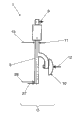
图2示出了根据图1的按本发明的废气门装置的优选实施方式沿着视线方向II的正视图。 FIG. 2 shows a front view of a preferred embodiment of the wastegate arrangement according to the invention according to FIG. 1 along the line of sight II.
图2示出了具有废气门轴5、弧形的中间块18以及废气门活门10的废气门装置1。废气力12作用到废气门活门10上。在废气门轴5上不可相对转动地安装了杠杆臂8。杠杆臂8的中间平面42与废气门活门10的中间平面43优选大致围成一个直角。杠杆臂8例如通过例如为花键轴连接的形状配合连接、例如为焊接的材料配合连接或者例如为夹紧连接的传力配合连接耦合到废气门轴5上。此外,该废气门装置1具有调节机构20,该调节机构通过耦合件31与杠杆臂8连接。该耦合件31例如构造成连杆。所述调节机构20优选是电动的或者气动的执行器。内燃机的马达控制器30通过数据线路29与调节机构20连接。
FIG. 2 shows a
杠杆臂力9可通过耦合件31由调节机构20施加到杠杆臂8上。通过将杠杆臂力9施加到杠杆臂8上,使得废气门轴5处于旋转中。可以这样关闭或者打开废气门阀门。根据内燃机的运行状态,马达控制器30通过数据线路29向调节机构20发出控制指令从而打开或者关闭废气门阀门。
The
图3示出了根据图1的按本发明的废气门装置的优选实施方式在打开废气门阀门时的俯视图。 FIG. 3 shows a plan view of a preferred embodiment of the wastegate arrangement according to the invention according to FIG. 1 with the wastegate valve open.
图3示出了废气门轴5连同废气门活门10、作用到杠杆臂上的杠杆臂力9以及作用到废气门活门10上的废气力12。为了简化示图,图3示出了没有第一和第二支承位置并且没有调节机构的废气门轴5。
FIG. 3 shows the
下面解释按本发明的废气门装置1在打开O废气门阀门时的功能。
The function of the
在打开O废气门阀门时,废气力12朝废气门活门10如此挤压,从而刚好压开废气门活门10。也就是说,所述调节机构必须通过杠杆臂施加杠杆臂力9,该杠杆臂力的大小使得废气刚好可以压开废气门活门10。由此,第一或者第二支承位置上的杠杆臂法向力11或者27小于第一或者第二支承位置中的废气法向力13或者28。杠杆臂法向力11和废气法向力13以相反的作用方向作用在第一支承位置上并且至少部分地相互抵消。通过在打开O时所述杠杆臂法向力11与废气法向力13没有完全抵消,从而在第一支承位置中相对于关闭废气门阀门时产生了更大的摩擦力矩。由此,调节机构以有利的方式与通常脉动的废气力12脱耦,由此利用按本发明的废气门装置显著改善了废气涡轮增压器的涡轮机的调节特性。
When the O wastegate valve is opened, the
图4示出了按本发明的废气门装置的另一优选实施方式的俯视图。 FIG. 4 shows a plan view of another preferred embodiment of the wastegate arrangement according to the invention.
图4示出了具有废气门轴5、弧形的中间块18以及废气门活门10的废气门装置1。此外,图4示出了第一和第二支承位置6、7,所述第一和第二支承位置布置在仅仅局部地示出的涡轮机壳体21中。在按本发明的废气门装置1的这种实施例中,所述废气门轴5在第一支承位置6上的直径D明显大于废气门轴5在第二支承位置7上的直径d。为了废气门轴5的有利的可装配性以及成本低廉的可制造性,该废气门轴在示出的实施方式中优选由构造成空心轴的第一单轴16以及构造成实心轴的第二单轴17组成。在此,第二单轴17穿过第一单轴16并且与其不可相对转动地、例如通过花键轴连接部进行连接。作为替代方案也可以将废气门轴5构造成单件的。
FIG. 4 shows the
因为在关闭废气门阀门时如前面所述几乎没有支承法向力作用在第一支承位置6上,因为杠杆臂法向力与废气法向力在第一支承位置中几乎完全抵消,所以第一支承位置6的较大的直径D在关闭时几乎不对形成摩擦力矩产生影响,调节机构除了由废气力产生的转矩外还必须克服该摩擦力矩。在第二支承位置7中通过尽可能小的轴直径d将摩擦影响保持得很小。
Since virtually no bearing normal force acts on the
相反,如果打开废气门阀门,那么第一支承位置6中的支承法向力上升并且由于较大的轴直径D产生较大的摩擦力矩。由此,在打开废气门阀门时所述调节机构以有利的类型和方式与通常脉动的废气力脱耦,由此能够显著改善这种废气门装置1的调节特性。
Conversely, if the wastegate valve is opened, the bearing normal force increases in the
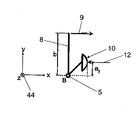
图5示出了根据图1的按本发明的废气门装置的优选实施方式在关闭废气门阀门时的简化的透视图。 FIG. 5 shows a simplified perspective view of a preferred embodiment of the wastegate arrangement according to the invention according to FIG. 1 with the wastegate valve closed.
图5示出了废气门轴5连同第一支承位置6、第二支承位置7、杠杆臂8、弧形的中间块18以及布置在弧形的中间块18上的废气门活门10。杠杆臂力9作用在杠杆臂8上。废气力12作用到废气门活门10上。此外,图5示出了关于具有x轴、y轴以及z轴的坐标系统44的废气门装置1。所述第一支承位置6构造成浮动支承并且第二支承位置7构造成固定支承。所述废气门轴5平行于坐标系统44的z轴。
FIG. 5 shows the
图6示出了根据图5的装置围绕z轴的力矩平衡情况。 FIG. 6 shows the moment balance about the z-axis of the device according to FIG. 5 .
图6示出了位于坐标系统44的z轴上的废气门轴5连同杠杆臂8以及废气门活门10。废气力12作用到废气门活门10上并且杠杆臂力9作用到杠杆臂8上。在围绕相当于废气门轴5的旋转轴线的旋转点B建立力矩平衡时,利用杠杆臂8的长度b以及相当于废气力12的围绕点B起作用的杠杆臂的长度ay获得以下关系式:
FIG. 6 shows the
其中: in:
,围绕z轴围绕点B的力矩之和, , the sum of moments about the point B about the z-axis,
Fbar,杠杆臂力9,以及
F bar ,
Fgas,废气力12。
F gas ,
图7示出了按图5的装置围绕y轴的力矩平衡情况。 FIG. 7 shows the moment balance about the y-axis of the device according to FIG. 5 .
图7示出了具有第一以及第二支承位置6、7的废气门轴5以及废气门活门10。杠杆臂力9作用到杠杆臂上并且废气力12作用到废气活门10上。合成的第一支承法向力34作用在第一支承位置6中,所述第一支承法向力是由废气法向力以及杠杆臂法向力在第一支承位置6中引起的。图7考虑了在相当于第二支承位置7的旋转点A中围绕坐标系统44的y轴作用的力矩的力矩平衡。废气力12围绕旋转点A以长度为h1的杠杆臂作用。杠杆臂力9同样围绕旋转点A以长度为h3的杠杆臂作用。假定合成的支承法向力34在第一支承位置6中等于零,那么获得以下关系式:
FIG. 7 shows the
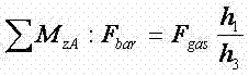
其中: in:

Fbar,杠杆臂力9,以及
F bar ,
Fgas,废气力12。
F gas ,
利用围绕z轴的力矩平衡


对于这种杠杆传动比来说,在关闭废气门阀门时在第一支承位置6中产生最小的摩擦力矩。
With this lever transmission ratio, a minimum frictional moment occurs in the
图8示出了废气门轴上的摩擦力矩关于废气门阀门上的废气压力的曲线。 FIG. 8 shows the friction torque on the wastegate shaft versus the exhaust gas pressure on the wastegate valve.
图8示出了在打开以及在关闭废气门阀门时力矩曲线的图表。示出的废气门阀门上的转矩M按比例缩放为废气门阀门上的废气压力并且在废气门轴的旋转角度α上绘出。所述废气压力导致废气力作用到废气门活门上。废气力矩37通过废气门活门施加到废气门轴上。在关闭废气门阀门时调节机构必须克服废气力矩37以及关闭摩擦力矩36。在打开废气门阀门时通过废气压开废气门阀门。所述调节机构必须克服打开摩擦力矩35并且刚好克服废气力矩37作用。 FIG. 8 shows a diagram of the torque curve when opening and closing the wastegate valve. The illustrated torque M at the wastegate valve is scaled to the exhaust gas pressure at the wastegate valve and is plotted over the angle of rotation α of the wastegate shaft. The exhaust gas pressure causes an exhaust gas force to act on the wastegate flap. An exhaust gas torque 37 is applied to the wastegate shaft via the wastegate flap. When closing the wastegate valve, the adjusting mechanism must overcome the exhaust gas torque 37 and the closing friction torque 36 . When opening the wastegate valve, the wastegate valve is opened by the exhaust gas pressure. The adjusting mechanism must act against the opening friction torque 35 and exactly against the exhaust gas torque 37 .
通过在关闭废气门活门时降低摩擦作用可以选择更小并且因此成本更低廉的调节机构,因为降低了用于关闭废气门活门的最大所需的转矩。 As a result of the reduced friction when closing the wastegate flap, a smaller and therefore less expensive actuating mechanism can be selected, since the maximum required torque for closing the wastegate flap is reduced.
在打开废气门阀门时摩擦作用的提高有利地使调节机构与废气的通常脉动的力脱耦。在打开废气门阀门时刚好通过废气压开废气门活门。因此,调节机构在打开时不必施加较大的转矩。 The increased friction when opening the wastegate valve advantageously decouples the adjusting mechanism from the generally pulsating forces of the exhaust gas. When opening the wastegate valve, the wastegate valve is opened exactly by the exhaust gas pressure. Therefore, the adjustment mechanism does not have to exert a large torque when opening.
由此,通过废气门轴的合适的支承或者在第一和第二支承位置中合适的杠杆传动比以及轴直径可如此改良按本发明的废气门装置,使得摩擦力矩在关闭废气门阀门时尽可能一样小并且在打开废气门阀门时尽可能多地消除。由此能够将调节机构的尺寸设计得更小,由此降低了其购置成本、所需的结构空间以及能量消耗。 Thus, by suitable mounting of the wastegate shaft or suitable lever transmission ratios and shaft diameters in the first and second mounting positions, the wastegate device according to the invention can be improved in such a way that the frictional torque is minimized when closing the wastegate valve. Probably as small and eliminate as much as possible when opening the wastegate valve. As a result, the adjustment mechanism can be dimensioned smaller, thereby reducing its acquisition costs, required installation space and energy consumption.
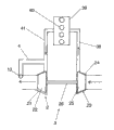
图9示出了按本发明的具有根据图1的废气门装置的废气涡轮增压机的优选实施方式的俯视图。 FIG. 9 shows a plan view of a preferred embodiment of an exhaust gas turbocharger according to the invention with a wastegate arrangement according to FIG. 1 .
具有多个气缸40的内燃机39通过废气管路41流体地与涡轮机2的布置在涡轮机壳体21中的涡轮22耦合。具有废气门活门10的废气门阀门4为废气示出了围绕涡轮机2的旁路。所述涡轮22通过涡轮增压机轴26与压缩机轮25不可相对转动地连接。该压缩机轮25布置在废气涡轮增压机3的压缩机23的压缩机壳体24中。所述压缩机轮25通过吸气侧38与内燃机39流体地耦合。
An
在具有废气涡轮增压机3的内燃机39的运行中,该内燃机39通过废气管路41向涡轮22提供废气。通过涡轮22降低了废气的焓并且将废气的动能以及热能转化成旋转能。该旋转能通过涡轮增压机轴26传递到压缩机轮25上。该压缩机轮25吸入新鲜空气,压缩该新鲜空气并且将压缩的新鲜空气通过吸气侧38供给内燃机39。
During operation of
通过在每体积单位的压缩的空气体积中存在更多的氧气,能够在内燃机39中每空气体积单位燃烧更多的氧气,由此提高了内燃机39的功率收益(Leistungsausbeute)。根据内燃机39的运行状态可以通过废气门阀门4引导废气在涡轮机2旁通过,例如在具有带有处于高转速全负荷状态下的废气涡轮增压机3的内燃机39的机动车的速度恒定较高时。通过引导一部分废气在涡轮机2旁通过可靠地防止内燃机39的过载。通过使废气涡轮增压机3具有按本发明的废气门装置,可以将用于调节废气门活门10所需的调节机构的尺寸如之前所述设计得更小。由此降低了具有带有按本发明的废气门装置的废气涡轮增压机3的内燃机39的重量、结构空间、制造成本以及能量消耗。
Due to the presence of more oxygen per volume unit of compressed air volume, more oxygen can be combusted per air volume unit in
示例性地理解提及的材料、数据以及尺寸并且仅仅用于解释本发明的实施方式以及改进方案。 The mentioned materials, data and dimensions are to be understood as examples and serve only to explain embodiments and developments of the invention.
所说明的用于涡轮机的废气门装置、用于废气涡轮增压机的涡轮机以及具有涡轮机的废气涡轮增压机能够特别有利地用在机动车领域中并且这里优选用在轿车中、例如柴油或汽油发动机中,然而在需要时也可以使用在其它任意的涡轮增压机应用中。 The described wastegate arrangement for a turbine, a turbine for an exhaust gas turbocharger and an exhaust gas turbocharger with a turbine can be used particularly advantageously in the motor vehicle sector and here preferably in passenger cars, for example diesel or In gasoline engines, however, it can also be used in any other turbocharger application if required.
Claims (15)
Applications Claiming Priority (3)
| Application Number | Priority Date | Filing Date | Title |
|---|---|---|---|
| DE102009048125.7 | 2009-10-02 | ||
| DE102009048125A DE102009048125B4 (en) | 2009-10-02 | 2009-10-02 | Wastegate arrangement for a turbine, turbine for an exhaust gas turbocharger, exhaust gas turbocharger for a motor vehicle and method for operating an exhaust gas turbocharger |
| PCT/EP2010/064069 WO2011039102A1 (en) | 2009-10-02 | 2010-09-23 | Waste gate arrangement for a turbine, turbine for an exhaust gas turbocharger, exhaust gas turbocharger, motor vehicle, and method for operating an exhaust gas turbocharger |
Publications (2)
| Publication Number | Publication Date |
|---|---|
| CN102575574A true CN102575574A (en) | 2012-07-11 |
| CN102575574B CN102575574B (en) | 2015-04-29 |
Family
ID=43400506
Family Applications (1)
| Application Number | Title | Priority Date | Filing Date |
|---|---|---|---|
| CN201080043965.9A Active CN102575574B (en) | 2009-10-02 | 2010-09-23 | Wastegate device, turbine, exhaust gas turbocharger and method of operation thereof |
Country Status (5)
| Country | Link |
|---|---|
| US (1) | US20120260651A1 (en) |
| EP (1) | EP2483540A1 (en) |
| CN (1) | CN102575574B (en) |
| DE (1) | DE102009048125B4 (en) |
| WO (1) | WO2011039102A1 (en) |
Cited By (3)
| Publication number | Priority date | Publication date | Assignee | Title |
|---|---|---|---|---|
| CN107524516A (en) * | 2016-06-15 | 2017-12-29 | 通用汽车环球科技运作有限责任公司 | Waste gate closing position location feature part |
| CN109653812A (en) * | 2017-10-11 | 2019-04-19 | 博格华纳公司 | Flap component, turbine and exhaust-driven turbo-charger exhaust-gas turbo charger for turbine |
| CN114991944A (en) * | 2021-03-01 | 2022-09-02 | 通用汽车环球科技运作有限责任公司 | Turbocharger waste gate actuator arm |
Families Citing this family (9)
| Publication number | Priority date | Publication date | Assignee | Title |
|---|---|---|---|---|
| DE102012012160A1 (en) * | 2012-06-19 | 2014-01-02 | GM Global Technology Operations, LLC (n.d. Ges. d. Staates Delaware) | Actuating unit for by-pass valve of turbocharger in motor vehicle, has valve opener rotatably mounted about pivot axis, where pivot arm converts force into moment acting on valve opener |
| DE102012024300A1 (en) | 2012-12-12 | 2014-06-12 | Daimler Ag | Valve device for a turbine of an exhaust gas turbocharger |
| US10066540B2 (en) | 2013-04-30 | 2018-09-04 | Borgwarner Inc. | Control arrangement of an exhaust-gas turbocharger |
| DE202013006097U1 (en) | 2013-07-04 | 2013-08-12 | Borgwarner Inc. | Stellanordnung an exhaust gas turbocharger |
| DE202014007538U1 (en) | 2014-09-17 | 2014-10-14 | Borgwarner Inc. | Stellanordnung an exhaust gas turbocharger |
| DE202014003918U1 (en) | 2014-05-08 | 2014-06-05 | Borgwarner Inc. | Stellanordnung an exhaust gas turbocharger |
| DE102015205966A1 (en) | 2015-04-01 | 2016-10-20 | Volkswagen Aktiengesellschaft | Wastegateventilsystem, exhaust gas turbocharger, internal combustion engine and motor vehicle |
| US10012138B2 (en) * | 2015-12-10 | 2018-07-03 | Honeywell International Inc. | Exhaust bypass valve of multi-stage turbocharger |
| CN113969829A (en) * | 2021-09-30 | 2022-01-25 | 东风商用车有限公司 | Supercharger bypass system |
Citations (5)
| Publication number | Priority date | Publication date | Assignee | Title |
|---|---|---|---|---|
| JPH0272436A (en) * | 1988-09-07 | 1990-03-12 | Fujitsu Ltd | Redundant system for microcomputer |
| US20050079049A1 (en) * | 2003-10-08 | 2005-04-14 | Aisin Seiki Kabushiki Kaisha | Exhaust gas sealing system for turbocharger |
| US20060053789A1 (en) * | 2004-08-13 | 2006-03-16 | Guenther Vogt | Exhaust gas regulating element for supercharger systems of internal combustion engines |
| EP1707790A1 (en) * | 2005-03-31 | 2006-10-04 | Cooper-Standard Automotive (Deutschland) GmbH | Exhaust gas recirculation system |
| EP1939427A2 (en) * | 2006-12-20 | 2008-07-02 | MP-Engineering GmbH | Exhaust turbocharger |
Family Cites Families (10)
| Publication number | Priority date | Publication date | Assignee | Title |
|---|---|---|---|---|
| DE2355773C3 (en) * | 1973-11-08 | 1978-06-08 | Honeywell Gmbh, 6000 Frankfurt | Valve |
| US4256285A (en) * | 1977-06-30 | 1981-03-17 | Honeywell Inc. | Eccentric rotary valve with control-improving wing member |
| DE3916221C2 (en) * | 1989-05-18 | 1998-03-19 | Audi Ag | Exhaust gas turbocharger |
| JPH0972436A (en) * | 1995-09-05 | 1997-03-18 | Hitachi Valve Kk | Eccentric rotary valve |
| DE10235013B4 (en) * | 2002-07-31 | 2004-07-22 | Siemens Ag | Method for determining a boost pressure setpoint in an internal combustion engine with an exhaust gas turbocharger |
| EP1491754A1 (en) * | 2003-06-25 | 2004-12-29 | BorgWarner, Inc. | Pneumatic actuator |
| US6981375B2 (en) | 2003-09-16 | 2006-01-03 | Detroit Diesel Corporation | Turbocharged internal combustion engine with EGR flow |
| JP5260082B2 (en) * | 2008-02-26 | 2013-08-14 | 三菱重工業株式会社 | Turbocharger exhaust bypass valve |
| DE102008011416A1 (en) * | 2008-02-27 | 2009-09-10 | Continental Automotive Gmbh | Turbocharger with an actuator for opening and closing a wastegate duct |
| DE102008011613A1 (en) * | 2008-02-28 | 2009-09-03 | Continental Automotive Gmbh | Turbocharger for petrol engine of vehicle, has actuating device for opening and closing wastegate channel, and provided with lifting magnet element coupled with wastegate flap, where lifting magnet element has iron core elements |
-
2009
- 2009-10-02 DE DE102009048125A patent/DE102009048125B4/en active Active
-
2010
- 2010-09-23 CN CN201080043965.9A patent/CN102575574B/en active Active
- 2010-09-23 EP EP10763331A patent/EP2483540A1/en not_active Withdrawn
- 2010-09-23 US US13/499,780 patent/US20120260651A1/en not_active Abandoned
- 2010-09-23 WO PCT/EP2010/064069 patent/WO2011039102A1/en not_active Ceased
Patent Citations (5)
| Publication number | Priority date | Publication date | Assignee | Title |
|---|---|---|---|---|
| JPH0272436A (en) * | 1988-09-07 | 1990-03-12 | Fujitsu Ltd | Redundant system for microcomputer |
| US20050079049A1 (en) * | 2003-10-08 | 2005-04-14 | Aisin Seiki Kabushiki Kaisha | Exhaust gas sealing system for turbocharger |
| US20060053789A1 (en) * | 2004-08-13 | 2006-03-16 | Guenther Vogt | Exhaust gas regulating element for supercharger systems of internal combustion engines |
| EP1707790A1 (en) * | 2005-03-31 | 2006-10-04 | Cooper-Standard Automotive (Deutschland) GmbH | Exhaust gas recirculation system |
| EP1939427A2 (en) * | 2006-12-20 | 2008-07-02 | MP-Engineering GmbH | Exhaust turbocharger |
Cited By (5)
| Publication number | Priority date | Publication date | Assignee | Title |
|---|---|---|---|---|
| CN107524516A (en) * | 2016-06-15 | 2017-12-29 | 通用汽车环球科技运作有限责任公司 | Waste gate closing position location feature part |
| CN109653812A (en) * | 2017-10-11 | 2019-04-19 | 博格华纳公司 | Flap component, turbine and exhaust-driven turbo-charger exhaust-gas turbo charger for turbine |
| CN109653812B (en) * | 2017-10-11 | 2023-02-28 | 博格华纳公司 | Valve flap assembly for a turbine, turbine and exhaust gas turbocharger |
| CN114991944A (en) * | 2021-03-01 | 2022-09-02 | 通用汽车环球科技运作有限责任公司 | Turbocharger waste gate actuator arm |
| CN114991944B (en) * | 2021-03-01 | 2023-06-27 | 通用汽车环球科技运作有限责任公司 | Turbocharger wastegate actuator arm |
Also Published As
| Publication number | Publication date |
|---|---|
| WO2011039102A1 (en) | 2011-04-07 |
| US20120260651A1 (en) | 2012-10-18 |
| DE102009048125B4 (en) | 2013-11-07 |
| EP2483540A1 (en) | 2012-08-08 |
| CN102575574B (en) | 2015-04-29 |
| DE102009048125A1 (en) | 2011-04-14 |
Similar Documents
| Publication | Publication Date | Title |
|---|---|---|
| CN102575574B (en) | Wastegate device, turbine, exhaust gas turbocharger and method of operation thereof | |
| EP2558752B1 (en) | Multifunction valve | |
| US7588047B2 (en) | Compressor bypass valve for use in multistage supercharging | |
| CN103998743B (en) | Manipulation device for the turbine of exhaust-driven turbo-charger exhaust-gas turbo charger | |
| CN103261587B (en) | Exhaust-gas turbocharger | |
| CN102575575B (en) | Turbine for exhaust gas turbocharger, exhaust gas turbocharger, motor vehicle and method for operating exhaust gas turbocharger | |
| US20130291539A1 (en) | Exhaust-gas turbocharger having a compressor housing with an integrated wastegate actuator | |
| CN105358798B (en) | Device for manipulating the waste gate valve of exhaust-driven turbo-charger exhaust-gas turbo charger | |
| CN106593622B (en) | Loaded turbocharger turbine waste gas bypass valve control linkage mechanism joint | |
| CN103270274B (en) | There is the exhaust-gas turbocharger of turbine cylinder and built-in wastegate actuator | |
| WO2007103860A2 (en) | Swing valve for a turbocharger with stacked valve members, and two-stage turbocharger system incorporating same | |
| JP2011523992A (en) | Shaft coupling with torsional rigidity, heat insulation, and multiple degrees of freedom to allow misalignment | |
| JP2011007185A (en) | Exhaust assembly | |
| EP3133260B1 (en) | Loaded turbocharger turbine wastegate control linkage joints | |
| CN104981596B (en) | Turbocharger including adjustment unit | |
| CN102803679A (en) | Turbocharger, And Method For Mounting A Regulation Device For A Turbocharger | |
| EP2915976B1 (en) | Turbocharger turbine wastegate mechanism | |
| US9890699B2 (en) | Turbocharger turbine wastegate mechanism | |
| CN108035794A (en) | A kind of automatically controlled by-passing valve design of turbocharging | |
| CN102713197A (en) | Transmission system and exhaust gas turbocharger | |
| SE520219C2 (en) | Valve and engine arrangement | |
| JP5874681B2 (en) | Valve drive device | |
| EP0578373B1 (en) | Exhaust brake and pressure modulation valve | |
| US9677462B2 (en) | Valve device for a turbine of an exhaust gas turbocharger | |
| JP2014231829A (en) | Valve drive device |
Legal Events
| Date | Code | Title | Description |
|---|---|---|---|
| C06 | Publication | ||
| PB01 | Publication | ||
| C10 | Entry into substantive examination | ||
| SE01 | Entry into force of request for substantive examination | ||
| C53 | Correction of patent of invention or patent application | ||
| CB02 | Change of applicant information |
Address after: Hannover Applicant after: CONTINENTAL AUTOMOTIVE GmbH Address before: Hannover Applicant before: Continental Automotive GmbH |
|
| C14 | Grant of patent or utility model | ||
| GR01 | Patent grant | ||
| TR01 | Transfer of patent right |
Effective date of registration: 20230412 Address after: Regensburg, Germany Patentee after: WeiPai Technology Co.,Ltd. Address before: Hannover Patentee before: CONTINENTAL AUTOMOTIVE GmbH |
|
| TR01 | Transfer of patent right |