CN102652257A - Means for detecting luminescent and/or light-scattering particles in flowing liquids - Google Patents
Means for detecting luminescent and/or light-scattering particles in flowing liquids Download PDFInfo
- Publication number
- CN102652257A CN102652257A CN2010800561275A CN201080056127A CN102652257A CN 102652257 A CN102652257 A CN 102652257A CN 2010800561275 A CN2010800561275 A CN 2010800561275A CN 201080056127 A CN201080056127 A CN 201080056127A CN 102652257 A CN102652257 A CN 102652257A
- Authority
- CN
- China
- Prior art keywords
- light
- pipeline
- particle
- window
- detector
- Prior art date
- Legal status (The legal status is an assumption and is not a legal conclusion. Google has not performed a legal analysis and makes no representation as to the accuracy of the status listed.)
- Pending
Links
Images

Classifications
-
- G—PHYSICS
- G01—MEASURING; TESTING
- G01N—INVESTIGATING OR ANALYSING MATERIALS BY DETERMINING THEIR CHEMICAL OR PHYSICAL PROPERTIES
- G01N15/00—Investigating characteristics of particles; Investigating permeability, pore-volume or surface-area of porous materials
- G01N15/10—Investigating individual particles
- G01N15/14—Optical investigation techniques, e.g. flow cytometry
-
- G—PHYSICS
- G01—MEASURING; TESTING
- G01N—INVESTIGATING OR ANALYSING MATERIALS BY DETERMINING THEIR CHEMICAL OR PHYSICAL PROPERTIES
- G01N15/00—Investigating characteristics of particles; Investigating permeability, pore-volume or surface-area of porous materials
- G01N15/02—Investigating particle size or size distribution
- G01N15/0205—Investigating particle size or size distribution by optical means
- G01N15/0227—Investigating particle size or size distribution by optical means using imaging; using holography
-
- G—PHYSICS
- G01—MEASURING; TESTING
- G01N—INVESTIGATING OR ANALYSING MATERIALS BY DETERMINING THEIR CHEMICAL OR PHYSICAL PROPERTIES
- G01N21/00—Investigating or analysing materials by the use of optical means, i.e. using sub-millimetre waves, infrared, visible or ultraviolet light
- G01N21/17—Systems in which incident light is modified in accordance with the properties of the material investigated
- G01N21/47—Scattering, i.e. diffuse reflection
-
- G—PHYSICS
- G01—MEASURING; TESTING
- G01N—INVESTIGATING OR ANALYSING MATERIALS BY DETERMINING THEIR CHEMICAL OR PHYSICAL PROPERTIES
- G01N21/00—Investigating or analysing materials by the use of optical means, i.e. using sub-millimetre waves, infrared, visible or ultraviolet light
- G01N21/62—Systems in which the material investigated is excited whereby it emits light or causes a change in wavelength of the incident light
- G01N21/63—Systems in which the material investigated is excited whereby it emits light or causes a change in wavelength of the incident light optically excited
- G01N21/64—Fluorescence; Phosphorescence
-
- G—PHYSICS
- G01—MEASURING; TESTING
- G01N—INVESTIGATING OR ANALYSING MATERIALS BY DETERMINING THEIR CHEMICAL OR PHYSICAL PROPERTIES
- G01N21/00—Investigating or analysing materials by the use of optical means, i.e. using sub-millimetre waves, infrared, visible or ultraviolet light
- G01N21/84—Systems specially adapted for particular applications
- G01N21/85—Investigating moving fluids or granular solids
-
- G—PHYSICS
- G01—MEASURING; TESTING
- G01N—INVESTIGATING OR ANALYSING MATERIALS BY DETERMINING THEIR CHEMICAL OR PHYSICAL PROPERTIES
- G01N33/00—Investigating or analysing materials by specific methods not covered by groups G01N1/00 - G01N31/00
- G01N33/18—Water
Landscapes
- Chemical & Material Sciences (AREA)
- Health & Medical Sciences (AREA)
- Life Sciences & Earth Sciences (AREA)
- Immunology (AREA)
- Analytical Chemistry (AREA)
- Biochemistry (AREA)
- General Health & Medical Sciences (AREA)
- General Physics & Mathematics (AREA)
- Physics & Mathematics (AREA)
- Pathology (AREA)
- Dispersion Chemistry (AREA)
- Engineering & Computer Science (AREA)
- Food Science & Technology (AREA)
- Medicinal Chemistry (AREA)
- Nuclear Medicine, Radiotherapy & Molecular Imaging (AREA)
- Investigating, Analyzing Materials By Fluorescence Or Luminescence (AREA)
- Optical Measuring Cells (AREA)
Abstract
Description
技术领域 technical field
本发明涉及用于探测在管线中流动的流体中的发光性和/或光散射性颗粒的探针和方法。 The present invention relates to probes and methods for detecting luminescent and/or light scattering particles in fluids flowing in pipelines.
背景技术 Background technique
在生产塑料时,监控生产过程是有决定性意义的,以便获得关于产品质量的及早的信息。尤其是,发光性或者发荧光性颗粒的数量是用于制造用于光学应用的成品、尤其是如CD-Rom、DVD的光学存储介质、光学部件、窗材料等等的塑料的可用性的决定性质量因素。 When producing plastics, it is decisive to monitor the production process in order to obtain early information on product quality. In particular, the quantity of luminescent or fluorescent particles is a decisive quality for the usability of plastics for the manufacture of finished products for optical applications, especially optical storage media such as CD-Rom, DVD, optical components, window materials, etc. factor.
由现有技术已知不同的用于探测在CD-Rom中的发光性颗粒的方法。例如完成的塑料粒料被熔化,作为CD被喷射并且在发光方面被研究。在另外的方法中,完成的塑料粒料被溶解并且溶液通过滤网被过滤。最后,经过滤的颗粒借助电子显微镜被评估。 Various methods are known from the prior art for detecting luminescent particles in CD-ROMs. For example, finished plastic pellets are melted, ejected as CDs and studied for luminescence. In another method, finished plastic pellets are dissolved and the solution is filtered through a strainer. Finally, the filtered particles are evaluated by means of an electron microscope.
明显的是,这些方法是耗费的并且不能实现在生产过程中的在线监督。 It is obvious that these methods are expensive and do not allow online supervision during the production process.
因此,存在对如下装置的需求,该装置能够在液体中实时地可靠并且精确地探测所有在预先给定的测量体积中出现的发光性颗粒,其中该液体在例如来自生产设备的管线中流动。在此该设备应该简单并且稳健地被构建并且尤其是能够经受在40巴(bar)的压力下直至400℃的温度。 Therefore, there is a need for a device which is able to reliably and precisely detect in real time all luminescent particles present in a predetermined measuring volume in a liquid which flows, for example, in a line from a production plant. In this case, the device should be of simple and robust construction and in particular be able to withstand temperatures up to 400° C. at a pressure of 40 bar (bar).
WO 2006/136147 A2描述了一种用于利用深度受限制的光片(Lichtscheibe)来探测散射光颗粒的设备,其中在光学受限制的测量体积中经过所述设备的颗粒借助相机来检测。在该设备中,在测量体积中达到无光收敛或发散的均匀照明,其中该测量体积在深度上借助深度受限制的光片狭窄地被限制,使得仅仅在该体积中流动的颗粒能够被看到。摄像机正交于光片,通过其分辨率仅仅描述测量体积的正交于摄像机取向的面的两个维度。通过借助分析软件的快速、高分辨率的图像检测和存储,不仅能够实现颗粒计数而且能够实现颗粒识别。在此,在两个图像之间必须保证,测量体积被交换达100%。在WO 2006/136147 A2中避免在较长的探测时间上记录颗粒,因为颗粒计数和识别会不再可靠。 WO 2006/136147 A2 describes a device for detecting scattered light particles with a depth-limited light sheet (Lichtscheibe), wherein particles passing the device in an optically limited measurement volume are detected by means of a camera. In this device, uniform illumination without light convergence or divergence is achieved in the measurement volume, wherein the measurement volume is narrowly limited in depth by means of a depth-limited light sheet, so that only particles flowing in the volume can be seen arrive. The camera is normal to the light sheet, and its resolution describes only the two dimensions of the plane of the measurement volume normal to the camera orientation. Through fast, high-resolution image detection and storage with the help of analysis software, not only particle counting but also particle identification are possible. In this case, it must be ensured that the measurement volume is exchanged by up to 100% between the two images. In WO 2006/136147 A2 recording of particles over longer detection times is avoided, since particle counting and identification would no longer be reliable.
但是,由于由发光性颗粒发射的光通常具有小的强度,因此探测器经常在其探测边界工作,从而运动的颗粒必须在较长的探测时间上被记录。 However, since the light emitted by the luminescent particles generally has a low intensity, the detectors often work at the limits of their detection, so that moving particles have to be recorded over a relatively long detection time.
从作为最接近现有技术的WO 2006/136147 A2出发,因此存在如下任务:提供一种用于探测在管线中的发光性颗粒的装置,该装置能够在由发光性颗粒发射的光和探测器噪声之间进行区别。 Starting from WO 2006/136147 A2, which is the closest prior art, there is therefore the following task: To provide a device for detecting luminescent particles in a pipeline which is able to detect the distinguish between noises.
US 2008/0019658描述了用于探测发光性流体的测量探针,其中该测量探针的壁由透明的流量波导管组成。在该流量波导管的下端部处放置有一个或多个探测器,所述探测器记下通过流量波导管积聚的被激励发光的颗粒的发射光。在此,颗粒探测是不可能的。 US 2008/0019658 describes a measuring probe for detecting luminescent fluids, wherein the wall of the measuring probe consists of a transparent flow waveguide. At the lower end of the flow waveguide are placed one or more detectors which register the emitted light of the excited luminescent particles accumulating through the flow waveguide. Here, particle detection is not possible.
JP 2005-300375 A描述了用于探测在流动的流体中的光散射性颗粒的探针,其中测量单元具有待测量流体流过的管线通道、管线的壁中的透明窗口和至少一个用于产生尺寸确定的激励光束(该激励光束通过该窗口照射在管线通道中的光散射性颗粒)的光源、以及至少一个探测器,其中所述探测器通过该窗口记录光散射性颗粒的电磁辐射。但是因为测量单元不是被构建为使得尺寸确定的激励光束与由光散射性颗粒发射的光相互垂直地定向,因此该设备不能实现在定义的景深上的照射。相应地不照射能够实现管线的图像记录的图像平面。 JP 2005-300375 A describes a probe for detecting light-scattering particles in a flowing fluid, wherein the measuring unit has a pipeline channel through which the fluid to be measured flows, a transparent window in the wall of the pipeline and at least one for generating A source of a dimensioned excitation beam that illuminates the light-scattering particles in the pipeline channel through the window, and at least one detector, wherein the detector records electromagnetic radiation of the light-scattering particles through the window. However, since the measuring unit is not designed such that the dimensionally defined excitation beam and the light emitted by the light-scattering particles are oriented perpendicularly to one another, this device cannot achieve illumination over a defined depth of field. Accordingly, the image plane that enables image recording of the pipeline is not illuminated.
US 6,309,886 B1公开了用于探测在流动的流体中的发荧光性颗粒的探针。在该探针中,流体通过通道的整个直径被运送,该流体借助光源被曝光,从而产生垂直于具有定义的景深的流体流的光平面、也即光体积。在该光体积中流过的发荧光性颗粒被光束激励并且其发射光借助CCD相机以预先定义的曝光时间在预先确定的积分时间上被记下。该积分时间可大于渡越时间或者匹配于渡越时间,以便改善探测的敏感性和颗粒分辨度。该流体通过排放通道被去除。在该设备中,尤其没有注意到,每个颗粒在平行于流体流的测量体积内直线运动。相应地,为了改善分析结果,使用用于在尤其是在通道边缘处的测量区域上减少流动变化的方法。为此,建议不同的用于图像校正的方法,或者由探测器仅仅记录通道的中央部分。 US 6,309,886 B1 discloses probes for detecting fluorescent particles in flowing fluids. In this probe, a fluid is conveyed through the entire diameter of the channel, which fluid is exposed by means of a light source, so that a light plane, ie a light volume, is produced perpendicular to the fluid flow with a defined depth of field. Fluorescent particles flowing through this light volume are excited by the light beam and their emitted light is recorded by means of a CCD camera with a predefined exposure time over a predefined integration time. The integration time can be greater than the time of flight or matched to the time of flight in order to improve the sensitivity and particle resolution of the detection. This fluid is removed through the discharge channel. In this device, it is especially not noticed that each particle moves linearly within the measurement volume parallel to the fluid flow. Accordingly, in order to improve the analysis results, methods are used for reducing flow variations over the measurement region, especially at the channel edges. For this purpose, different methods for image correction are proposed, or only the central part of the channel is recorded by the detector.
发明内容 Contents of the invention
从作为最接近现有技术的US 6,309,886 B1出发,因此存在的任务是,提供用于探测在管线中的发光性颗粒的装置,该装置能够在由发光性颗粒所发射的光和探测器噪声之间进行区别,能够简单地监控整个管线并且能够匹配于生产设备的参数。 Starting from US 6,309,886 B1, which is the closest prior art, it is therefore the task to provide a device for detecting luminescent particles in pipelines which is able to distinguish between the light emitted by the luminescent particles and the noise of the detector. Differentiate between them, the entire pipeline can be easily monitored and adapted to the parameters of the production equipment.
该任务通过用于探测在流动的流体中的发光性和可选光散射性颗粒的探针解决,该探针具有包括如下元件的测量单元: This task is solved by a probe for detecting luminescent and optionally light-scattering particles in flowing fluids, which probe has a measuring cell comprising the following elements:
-待测量的流体流过的管线通道, - the pipeline channel through which the fluid to be measured flows,
-至少一个在管线的壁中的透明窗口, - at least one transparent window in the wall of the pipeline,
-至少一个用于产生尺寸确定的激励光束的光源,所述激励光束在光学受限制的测量体积中通过窗口激励在管线通道中的发光性颗粒和光散射性颗粒, - at least one light source for generating a dimensionally determined excitation beam which excites the luminescent and light-scattering particles in the pipeline channel through a window in the optically confined measurement volume,
-至少一个探测器,其通过该窗口或通过另一窗口记录发光性颗粒和可选光散射性颗粒的电磁辐射, - at least one detector which records the electromagnetic radiation of the luminescent particles and optionally light-scattering particles through the window or through another window,
其中所述测量单元被构建为使得尺寸确定的激励光束和发射的光相互垂直地定向,每个颗粒在测量体积内平行于流体流直线地运动,并且流体流以相对激励光的固定的角度流动,其中流体流、探测器和光源处于一个平面中(图1,3,6b)。按照本发明,探测器具有至用于控制积分时间的元件的接口,该元件用于输入试样体积的高度和输入流速以及计算和控制积分时间,从而探测器在颗粒在输入的流速情况下流过光体积所需的时间上记录由发光性颗粒所发射的光。 wherein the measurement cell is constructed such that the dimensionally determined excitation beam and the emitted light are oriented perpendicularly to each other, each particle moves linearly within the measurement volume parallel to the fluid flow, and the fluid flow flows at a fixed angle relative to the excitation light , where the fluid flow, detector and light source are in one plane (Fig. 1, 3, 6b). According to the invention, the detector has an interface to an element for controlling the integration time, which is used to input the height of the sample volume and the input flow rate and to calculate and control the integration time, so that the detector flows through at the input flow rate The light emitted by the luminescent particle is recorded over the time required for the light volume.
在本发明中,可以在较长的探测时间、也即连续地记录颗粒,其中在该探测时间期间颗粒在流动的流体中继续运动。 In the present invention, particles can be recorded over longer detection times, ie continuously, during which the particles continue to move in the flowing fluid.
在本发明的另一实施方式中,探测器在积分时间上记录图像系列,所述图像系列在该时间上被相加。在所述图像系列上的颗粒跟踪需要更加光敏感的相机,以便识别出颗粒,但是是明显更简单的,以便颗粒不多次被计数,尤其是在具有棱形窗口的探针的情况下。此外,该方法还具有避免噪声的优点。 In a further embodiment of the invention, the detector records an image series over an integration time at which time the image series are added. Particle tracking on the image series requires a more light-sensitive camera in order to recognize the particles, but is significantly simpler so that the particles are not counted more than once, especially in the case of probes with prismatic windows. In addition, this method has the advantage of avoiding noise.
每个颗粒都具有对准的流动,并且能够在较长的探测时间上作为光点或作为对准的光痕迹(Lichtspur)被记录,这能够实现可靠的图像分析。 Each particle has an aligned flow and can be recorded as a light spot or as an aligned light trace (Lichtspur) over a long detection time, which enables reliable image analysis.
通过每个颗粒的由探针的构造所决定的对准的流动,耗费的校准或图像的校正是不需要的。 Due to the aligned flow of each particle, which is determined by the configuration of the probe, no complicated calibration or correction of the image is necessary.
本发明的第一主题因此是用于探测在流动的流体中的发光性颗粒和可选光散射性颗粒的探针,该探针具有包括如下元件的测量单元: A first subject of the invention is therefore a probe for detecting luminescent particles and optionally light-scattering particles in a flowing fluid, which probe has a measuring cell comprising the following elements:
-待测量的流体流过的管线通道, - the pipeline channel through which the fluid to be measured flows,
-至少一个在管线的壁中的透明窗口, - at least one transparent window in the wall of the pipeline,
-至少一个用于产生尺寸确定的激励光束的光源,所述激励光束在光学受限制的光体积中通过窗口激励在管线通道中的发光性颗粒和光散射性颗粒, - at least one light source for generating a dimensionally determined excitation beam that excites the luminescent and light-scattering particles in the pipeline channel through a window in an optically confined light volume,
-至少一个探测器,其通过该窗口或通过另一窗口记录发光性颗粒和可选光散射性颗粒的电磁辐射, - at least one detector which records the electromagnetic radiation of the luminescent particles and optionally light-scattering particles through the window or through another window,
-用于控制积分时间的元件,该元件用于输入试样体积的高度和输入流速以及计算和控制积分时间,其中积分时间是颗粒在输入的流速情况下流过光体积所需的时间, - an element for controlling the integration time, which is used to input the height of the sample volume and the input flow rate and to calculate and control the integration time, wherein the integration time is the time required for the particles to flow through the light volume at the input flow rate,
其中测量单元被构建为使得尺寸确定的激励光束和所发射的光相互垂直地定向, where the measuring cell is constructed such that the dimensionally determined excitation beam and the emitted light are oriented perpendicularly to each other,
其中每个颗粒在测量体积内平行于流体流运动,所述流体流以相对激励光的固定的角度流动, wherein each particle moves within the measurement volume parallel to a fluid flow flowing at a fixed angle relative to the excitation light,
其中流体流、探测器和光源处于一个平面中, where the fluid flow, detector and light source are in one plane,
其中探测器具有至用于控制积分时间的元件的接口,使得探测器在颗粒在输入的流速情况下流过光体积所需的时间上记录由发光性颗粒所发射的光。 In this case, the detector has a connection to an element for controlling the integration time, so that the detector registers the light emitted by the luminescent particle over the time required for the particle to flow through the light volume at an input flow rate.
优选地,颗粒流相对激励光的固定的角度处于45至135度的范围中。 Preferably, the fixed angle of the particle flow relative to the excitation light is in the range of 45 to 135 degrees.
为了能够借助其发射光的强度明确地识别发光性颗粒,所述强度在确定时间(也称为积分时间)上被相加。积分时间被定义为颗粒在固定的流速情况下流过试样体积所需的时间。在本发明中,探测器相应地具有至用于控制积分时间的元件的接口,从而探测器在颗粒在定义的流速情况下流过光体积所需的时间上记录由发光性颗粒发射的光。用于控制积分时间的元件通常是计算机的一部分。 In order to be able to unambiguously identify the luminescent particles by means of the intensity of their emitted light, the intensities are added over a certain time (also referred to as integration time). Integration time is defined as the time required for a particle to flow through the sample volume at a fixed flow rate. In the present invention, the detector accordingly has an interface to an element for controlling the integration time, so that the detector registers the light emitted by the luminescent particle over the time required for the particle to flow through the light volume at a defined flow rate. The elements used to control the integration time are usually part of the computer.
典型地,利用本发明的设备监督直径为0.5至50mm、优选4至30mm的管线。在此,应注意的是,探测分辨率在管线直径上升的情况下下降。相应地,光源和探测器必须匹配于管线直径或者分辨率损失必须利用合适的装置(例如高分辨率的光敏感的相机)、强力的光源(例如激光光源或氙灯)来补偿。 Typically, pipelines with a diameter of 0.5 to 50 mm, preferably 4 to 30 mm, are supervised with the device of the invention. It should be noted here that the detection resolution decreases with increasing pipeline diameter. Accordingly, the light source and detector must be adapted to the pipe diameter or loss of resolution must be compensated with suitable devices (eg high-resolution light-sensitive cameras), powerful light sources (eg laser light sources or xenon lamps).
管线的材料是任意的,通常使用金属制成的管线。 The material of the pipe is arbitrary, but usually a pipe made of metal is used.
典型地,作为用于激励发光性颗粒的光源与激励过滤器、具有合适发射波的激光器或大功率LED组合地使用氙灯。 Typically, xenon lamps are used as light sources for exciting the luminescent particles in combination with excitation filters, lasers with suitable emission waves or high-power LEDs.
典型地,发光性颗粒借助波长为400至500nm情况下的光束来激励。 Typically, the luminescent particles are excited by means of a light beam at a wavelength of 400 to 500 nm.
由光源生产的激励光束通常通过在管线壁中所引入的窗口在管线通道的整个管线直径上被射入。激励光束的尺寸定义了光学受限制的测量体积。同样,整个管线直径由探测器记录。在此特别的优点是,通过管线的小片段(测量体积)的图像记录可以在该时间上检测管线的完整内容。在需要时,激励光束的几何结构借助圆柱形透镜或波导管横截面转换器来构成。 The excitation light beam produced by the light source is usually injected over the entire pipeline diameter of the pipeline channel through windows introduced in the pipeline wall. The size of the excitation beam defines the optically limited measurement volume. Likewise, the entire pipeline diameter is recorded by the detector. A particular advantage here is that the complete content of the pipeline can be detected at this time by image recording of a small segment (measurement volume) of the pipeline. If necessary, the geometry of the excitation beam is formed by means of cylindrical lenses or waveguide cross-section converters.
通常,尺寸确定的激励光束相对由发光性颗粒发射的光的垂直定向通过光源和探测器彼此间的垂直定向来保证。代替地,可以借助棱镜和反射镜来实现相应光束彼此间必要的定向。 Usually, the perpendicular alignment of the dimensionally defined excitation beam relative to the light emitted by the luminescent particles is ensured by the perpendicular alignment of the light source and the detector relative to each other. Alternatively, the necessary alignment of the respective light beams relative to one another can be achieved by means of prisms and mirrors.
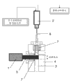
在本发明探针的第一实施方式中,用于用激励光照射管线通道的透明窗口(照明窗口)以及用于借助探测器记录发射光的另外的透明窗口(探测窗口)处于管线壁中。在该特别的实施方式(参见图1)中,管线以90°的角度折弯。照明窗口在管线的一侧处于弯曲之前,并且探测窗口在管线的该侧直接地处于该弯曲之后,从而探测窗口在管线通道的下部是开放的,并且探测器记录流向所述探测器的流体流。该实施方式具有特别的优点:该流以相对流动方向的为0度的固定的角度被观察,并且每个颗粒相应地作为点被探测,前提是所述颗粒在整个积分时间期间垂直于激励光直线地运动。 In a first embodiment of the probe according to the invention, a transparent window for illuminating the pipeline channel with excitation light (illumination window) and a further transparent window for recording the emitted light by means of a detector (detection window) are located in the pipeline wall. In this particular embodiment (see FIG. 1 ), the pipeline is bent at an angle of 90°. the illumination window is in front of the bend on one side of the pipeline and the detection window is directly behind the bend on that side of the pipeline so that the detection window is open in the lower part of the pipeline channel and the detector registers the fluid flow to said detector . This embodiment has the particular advantage that the flow is observed at a fixed angle of 0 degrees relative to the flow direction, and each particle is detected accordingly as a point, provided that the particle is perpendicular to the excitation light during the entire integration time Move in a straight line.
在本发明的该实施方式中,有利的是,光体积最大是探测器的景深范围的两倍高,典型地,激励光束被聚集在100μm至10mm、优选150μm至3mm的厚度上。如果测量体积大于景深范围,则颗粒不再被精确地测量。如果仅仅要求一次探测事件,则该测量体积应该仅尽可能大,以便收集尽可能多的光。 In this embodiment of the invention, the light volume is advantageously at most twice as high as the depth-of-field range of the detector, typically the excitation beam is focused on a thickness of 100 μm to 10 mm, preferably 150 μm to 3 mm. If the measurement volume is larger than the depth-of-field range, the particles are no longer accurately measured. If only one detection event is required, the measurement volume should only be as large as possible in order to collect as much light as possible.
因为管线的角度也在弯曲之前影响线路中的流体流的方向,因此有利的是,测量单元的构造直线地支持颗粒不受阻碍在测量体积内的层状流动,也即没有死空间并且在恒定速度情况下。为此,可以单独地或者相互组合地使用不同的装置。 Since the angle of the line also affects the direction of the fluid flow in the line before it is bent, it is advantageous that the configuration of the measuring cell supports the laminar flow of the particles in a straight line unhindered within the measurement volume, i.e. without dead spaces and at constant speed case. For this purpose, various devices can be used individually or in combination with each other.
例如优选的是,将窗玻璃与管线通道齐平地固定到管线壁中。窗口的形状是任意的,通常是直径为2至100mm的圆形。代替地,探针可以由蓝宝石或石英玻璃制造,所述探针被固定在管线处。 For example, it is preferred to fasten the window pane flush with the line channel in the line wall. The shape of the window is arbitrary, usually circular with a diameter of 2 to 100 mm. Alternatively, the probe can be made of sapphire or quartz glass, said probe being fixed at the pipeline.
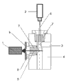
为了在塑料生产设备中的可用性,窗口必须经受在直至400℃温度和1至250巴的压力下熔液的流动。典型地,窗口由蓝宝石或石英玻璃组成,由于其特别的坚固性优选由蓝宝石组成,具有10mm的厚度并且如例如在DE 102 01 541 A1中描述的那样被成形为锥状的。通过借助玻璃金属密封的压力,窗口元件可以与管线通道齐平地被固定到管线壁中(图3)。 For usability in plastics production plants, windows must withstand the flow of melts at temperatures up to 400° C. and pressures of 1 to 250 bar. Typically, the window consists of sapphire or quartz glass, preferably sapphire due to its particular robustness, has a thickness of 10 mm and is conically shaped as described, for example, in DE 102 01 541 A1. By means of the pressure of the glass-to-metal seal, the window element can be fixed flush with the pipeline channel into the pipeline wall (Fig. 3).
此外,优选的是,为了颗粒的最佳流动,从照明窗口的中心起与探测窗口的表面的距离d被匹配于管线的大小(图4)。根据应用领域,此外有利的是,距离d匹配于流速和所研究的流体的粘度,以便优化在测量区域内的层状流动。 Furthermore, it is preferred that the distance d from the center of the illumination window to the surface of the detection window is adapted to the size of the pipeline for an optimal flow of particles ( FIG. 4 ). Depending on the field of application, it is also advantageous if the distance d is adapted to the flow velocity and the viscosity of the fluid under investigation in order to optimize the laminar flow in the measurement range.
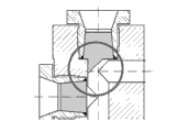
也可能的是,如此构成探测窗口,使得管线的在90°角度的死空间是最小的。为此,探测窗口的构造可以如例如在图5中所示地被匹配。 It is also possible to design the detection window in such a way that the dead space of the line at an angle of 90° is minimal. For this purpose, the configuration of the detection window can be adapted as shown, for example, in FIG. 5 .
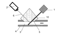
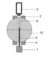
在本发明探针的第二实施方式中,借助棱镜来实现相应光束彼此间必要的定向。于是测量单元通常具有唯一的窗口,该窗口在管线的边缘处被置入在管线壁中并且具有棱镜作为窗玻璃(图5和6)。代替地,由蓝宝石或石英玻璃制成的探针可以被制造为具有适当的棱形几何结构,所述探针被固定在管线处。 In a second embodiment of the probe according to the invention, the necessary alignment of the respective light beams relative to one another is achieved by means of prisms. The measuring unit then usually has a single window, which is inserted into the line wall at the edge of the line and has a prism as window pane ( FIGS. 5 and 6 ). Alternatively, a probe made of sapphire or quartz glass can be manufactured with a suitable prismatic geometry, said probe being fixed at the pipeline.
该特别的实施方式具有优点:流体流可以不受阻碍地流过该窗口。光源、探测器的定位和棱镜的几何结构和光学特性确保激励光相对发射光的适当的垂直定向。在相对流动方向优选45°或135°的固定的角度上进行观察。在该实施中,颗粒作为对准的线被记录。 This particular embodiment has the advantage that the fluid flow can flow through the window unimpeded. The positioning of the light source, detectors and the geometry and optical properties of the prisms ensure proper vertical orientation of the excitation light relative to the emitted light. The observation is made at a fixed angle of preferably 45° or 135° relative to the direction of flow. In this implementation, the particles are recorded as aligned lines.
在棱镜实施中,激励光束的厚度优选比管线直径薄。有利的是,最大为5mm、优选150μm至3mm的厚度,但是其取决于流动通道的直径。例如针对5mm的流动通道直径,优选最大1mm的光束厚度。如果测量体积大于景深范围,则颗粒不再被精确地测量。如果仅仅需要一次探测事件,则该测量体积应该仅仅尽可能大,以便收集尽可能多的光。 In a prism implementation, the thickness of the excitation beam is preferably thinner than the diameter of the pipeline. A thickness of at most 5 mm, preferably 150 μm to 3 mm is advantageous, but this depends on the diameter of the flow channel. For example for a flow channel diameter of 5 mm, a beam thickness of at most 1 mm is preferred. If the measurement volume is larger than the depth-of-field range, the particles are no longer accurately measured. If only one detection event is required, the measurement volume should only be as large as possible in order to collect as much light as possible.
对于所描述的实施方式1和2,可能有利的是,直接借助加热元件来加温测量单元,从而流过的流体的温度可以被保持恒定。典型的加热元件是通过加热管道的油附带加热或电加热。
For the described
在本发明中,探测器可以记下通常在500至700nm波长情况下的由发光性颗粒发射的光的强度。如果由该探测器记下由光散射性颗粒发射的光的强度,则这通常发生在激励波长处。必要时,使用发射过滤器,以便选择性地检测该波长范围。 In the present invention, the detector can register the intensity of the light emitted by the luminescent particle, typically at a wavelength of 500 to 700 nm. If the intensity of the light emitted by the light-scattering particles is registered by the detector, this usually occurs at the excitation wavelength. If necessary, use emission filters to selectively detect this wavelength range.
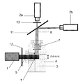
也可能的是,使用多个探测器,其中可以将用于探测发光性颗粒的探测器和用于探测光散射性颗粒的探测器组合(例如如在图10中所示)。 It is also possible to use a plurality of detectors, wherein a detector for detecting luminescent particles and a detector for detecting light-scattering particles can be combined (as shown for example in FIG. 10 ).
可能的探测器例如是CCD相机、CMOS相机、放大器相机、光电倍增器、光电池。合适的相机是在探测波范围(500-700nm)中足够光敏感的相机。例如,使用AVT公司的相机Stingray(根据模型,图像频率为9至84 fqs)。相机的优点在于,不仅能够检测颗粒的发光强度而且能够检测颗粒的面。 Possible detectors are eg CCD cameras, CMOS cameras, amplifier cameras, photomultipliers, photocells. A suitable camera is one that is sufficiently light-sensitive in the probe wave range (500-700 nm). For example, use the camera Stingray from the company AVT (image frequency from 9 to 84 fqs depending on the model). The advantage of the camera is that not only the luminous intensity of the particles but also the surface of the particles can be detected.
按照本发明,光源连续地或者在积分时间上照射流动通道的试样体积并且激励流过的颗粒。 According to the invention, the light source illuminates the sample volume of the flow channel continuously or over an integration time and excites the particles flowing through.
通常,积分时间被匹配于试样体积的大小和流速。 Typically, the integration time is matched to the sample volume size and flow rate.
探测器在积分时间上记录来自通道内部的发射光并且将该信息转发给图像分析单元,该图像分析单元通常是计算机的一部分。 The detector registers the emitted light from the inside of the channel over the integration time and forwards this information to an image analysis unit, which is usually part of a computer.
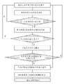
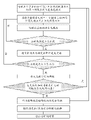
图像材料的分析典型地按照图7的图解来进行,数据被评估并且被输出。 Analysis of image material is typically performed according to the diagram of Figure 7, data is evaluated and output.
本发明的另外的主题因此是用于探测在流过本发明探针的流体中的发光性颗粒和可选光散射性颗粒的方法,具有下面的步骤: A further subject of the invention is therefore a method for detecting luminescent particles and optionally light-scattering particles in a fluid flowing through a probe according to the invention, with the following steps:
-输入光体积的高度并且输入流速以及在用于控制积分时间的元件中计算积分时间,其中积分时间是颗粒在定义的流速情况下流过光体积所需的时间, - enter the height of the light volume and enter the flow rate and calculate the integration time in the element for controlling the integration time, where the integration time is the time required for a particle to flow through the light volume at a defined flow rate,
-通过光源激励光,用于定义光体积, - excitation of light by light sources, used to define light volumes,
-在积分时间上借助探测器探测发射辐射, - detection of emitted radiation by means of a detector over the integration time,
-借助图像分析单元分析探测数据, - analysis of detection data with the aid of an image analysis unit,
-输出颗粒数量和/或颗粒大小分布和/或每体积和/或每重量的颗粒强度分布和/或输出在确定的时间上发光性颗粒的聚集图像。 outputting particle number and/or particle size distribution and/or particle intensity distribution per volume and/or per weight and/or outputting an aggregation image of the luminescent particles over a defined time.
本发明的另外的主题是,使用本发明探针和/或本发明方法用于在线监控生产设备、尤其是塑料生产设备、净化设备。 A further subject of the invention is the use of the probe according to the invention and/or the method according to the invention for on-line monitoring of production plants, in particular plastics production plants, cleaning plants.
图1,3至6示出本发明设备的可能的实施,本发明不限于此。 Figures 1, 3 to 6 show possible implementations of the device of the invention, without the invention being restricted thereto.
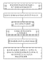
图2和7或11示出了发明性方法的流程以及在图像分析单元中的图像分析的流程,但其不限于此。 2 and 7 or 11 show the sequence of the inventive method and the sequence of the image analysis in the image analysis unit, but are not limited thereto.
如果在积分时间上可以记录图像系列,则可以在图像分析单元中的图像分析之前将图像相加并且按照图7来继续该分析。在该情况下,图像是被相加的图像。 If the image series can be recorded over the integration time, the images can be added before the image analysis in the image analysis unit and the analysis can be continued according to FIG. 7 . In this case, the images are the added images.
代替地,图像分析单元可以按照图11来执行图像分析,并且在图像分析的范围中进行相加。 Alternatively, the image analysis unit can perform an image analysis according to FIG. 11 and perform the addition within the scope of the image analysis.
附图说明 Description of drawings
图1示出了借助实施方式1的本发明探针;
Fig. 1 shows the probe of the present invention by means of
图2示出了方法图; Figure 2 shows a method diagram;
图3示出了实施方式1;
Figure 3 shows
图4示出了在实施方式1情况下距离d的优化;
Figure 4 shows the optimization of the distance d in the case of
图5示出了实施方式1的窗口变型;
FIG. 5 shows a window modification of
图6a示出了具有棱镜的实施方式2的侧视图;
Figure 6a shows a side view of
图6b示出了具有棱镜的实施方式2的从上面的视图;
Figure 6b shows a view from above of
图7示出了在该实施方式中图像分析单元中的图像分析的图解,其中在等于积分时间的较长探测时间上连续记录颗粒; Figure 7 shows a diagram of the image analysis in the image analysis unit in this embodiment, wherein particles are continuously recorded over a longer detection time equal to the integration time;
图8示出了在该时间上每克熔液的发荧光性颗粒的数量的输出; Figure 8 shows the output of the number of fluorescent particles per gram of melt over time;
图9示出了在6个小时上发荧光性颗粒的聚集图像; Figure 9 shows aggregation images of fluorescent particles over 6 hours;
图10示出了用于同时探测发光性颗粒和光散射性颗粒的探针; Figure 10 shows a probe for simultaneous detection of luminescent particles and light-scattering particles;
图11示出了在该实施方式中在图像分析单元中的图像分析的图解,其中在积分时间上记录图像系列。 FIG. 11 shows a diagram of the image analysis in the image analysis unit in this embodiment, wherein an image series is recorded over an integration time.
附图标记: Reference signs:
1 光源 1 light source
2探测器 2 detectors
2a用于探测发光性颗粒的探测器 2a Detectors for detecting luminescent particles
2b 用于探测光散射性颗粒的探测器 2b Detectors for detecting light-scattering particles
3 管线通道 3 pipeline channels
4 管线壁 4 pipeline wall
5 激励光束 5 excitation beams
6 发射光 6 emit light
7 窗玻璃 7 window glass
8 玻璃金属密封 8 glass metal seal
9 孔径 9 aperture
10 棱镜 10 prisms
11 分色镜 530nm 11 dichroic mirror 530nm
12 激励过滤器400-500nm 12 excitation filter 400-500nm
13 荧光过滤器550-650nm。 13 Fluorescence filter 550-650nm.
例子:example:
具有8mm直径的管线通道的管线以90°角度折弯。 The pipeline with the pipeline channel of 8 mm diameter is bent at an angle of 90°.
在管线壁中,在管线的一侧在该弯曲之前铣削照明窗口并且在管线的该侧直接在该弯曲之后铣削探测窗口,从而该探测窗口在管线通道的下部是开放的并且该探测器能够记录流向该探测器的流体流。 In the pipeline wall, an illumination window is milled on one side of the pipeline before the bend and a detection window is milled on this side of the pipeline directly after the bend, so that the detection window is open in the lower part of the pipeline channel and the detector is able to record Fluid flow to the detector.
从照明窗口的中心起与探测窗口的表面的距离d为14mm。 The distance d from the center of the illumination window to the surface of the detection window is 14 mm.
这些窗口两者都是具有9mm直径的圆形。在每个窗口中,通过压力借助玻璃金属密封与管线通道齐平地固定10mm厚的锥状成形的由蓝宝石制成的窗玻璃(图3)。 These windows are both circular with a diameter of 9 mm. In each window, a 10 mm thick conically shaped window pane made of sapphire is fixed flush with the pipeline channel by means of a glass-to-metal seal ( FIG. 3 ).
探针被装入聚碳酸酯设备的管线中,其中聚碳酸酯熔液在300℃的温度下以6m/min的流速流动。 The probe was loaded into the pipeline of a polycarbonate plant in which the polycarbonate melt flowed at a temperature of 300° C. at a flow rate of 6 m/min.
在照明窗口之前,与激励过滤器(HQ450/100 M-2P LOT Oriel)和孔径组合地固定商业上可用的氙灯(Drelloscop 255, Drello公司)。光束的激励波长借助激励过滤器被调节到400-500nm上。该光束借助孔径被聚焦到2mm的平均直径上。 A commercially available xenon lamp (Drelloscop 255, Drello Corporation) was mounted in combination with an excitation filter (HQ450/100 M-2P LOT Oriel) and aperture prior to illuminating the window. The excitation wavelength of the beam is adjusted to 400-500 nm by means of an excitation filter. The beam is focused by means of an aperture to an average diameter of 2 mm.
在探测窗口之前,与发射过滤器(LOT Oriel公司的HQ600/100M-2P)和分束器(LOT Oriel公司的530DCXRU )组合地固定相机(AVT公司的Stingray F-033B , 直至 58 fps),用于选择在550至650nm的波长范围中记录。该相机垂直于激励光地被固定,使得该相机可以记录管线通道的整个直径。 Before the detection window, a camera (Stingray F-033B from AVT, up to 58 fps) was fixed in combination with an emission filter (HQ600/100M-2P from LOT Oriel) and a beam splitter (530DCXRU from LOT Oriel), with Recorded in a wavelength range selected from 550 to 650 nm. The camera is fixed perpendicular to the excitation light so that it can record the entire diameter of the pipeline channel.
该相机的接口与用于控制积分时间的元件以及与图像分析单元、即计算机的两个元件连接。 The interface of the camera is connected to the elements for controlling the integration time and to the two elements of the image analysis unit, ie the computer.
在用于控制积分时间的元件中,输入试样体积的高度(2mm)和流速。20ms的积分时间被计算出。光源在400-500nm波长情况下连续照射该试样体积。 In the element used to control the integration time, enter the height (2 mm) and flow rate of the sample volume. An integration time of 20ms is calculated. A light source continuously illuminates the sample volume at a wavelength of 400-500 nm.
相机在550至650nm探测波长范围中在通过用于控制积分时间的元件控制的积分时间上记录试样体积的图像。 The camera records an image of the sample volume in the detection wavelength range of 550 to 650 nm at an integration time controlled by an element for controlling the integration time.
所记录的数据由相机传输到图像分析单元中并且由图像分析单元按照图7处理。 The recorded data are transmitted from the camera to the image analysis unit and processed by the image analysis unit according to FIG. 7 .
图8和9示出了在处理数据之后可能的输出。 Figures 8 and 9 show possible outputs after processing the data. the
Claims (15)
Applications Claiming Priority (3)
| Application Number | Priority Date | Filing Date | Title |
|---|---|---|---|
| EP09015341.2 | 2009-12-11 | ||
| EP09015341A EP2333515A1 (en) | 2009-12-11 | 2009-12-11 | Device for detecting luminous and/or light-diffusing particles in flowing liquids |
| PCT/EP2010/068998 WO2011069976A1 (en) | 2009-12-11 | 2010-12-06 | Means for detecting luminescent and/or light-scattering particles in flowing liquids |
Publications (1)
| Publication Number | Publication Date |
|---|---|
| CN102652257A true CN102652257A (en) | 2012-08-29 |
Family
ID=42077159
Family Applications (1)
| Application Number | Title | Priority Date | Filing Date |
|---|---|---|---|
| CN2010800561275A Pending CN102652257A (en) | 2009-12-11 | 2010-12-06 | Means for detecting luminescent and/or light-scattering particles in flowing liquids |
Country Status (11)
| Country | Link |
|---|---|
| US (1) | US20120281203A1 (en) |
| EP (2) | EP2333515A1 (en) |
| JP (1) | JP2013513789A (en) |
| KR (1) | KR20120092188A (en) |
| CN (1) | CN102652257A (en) |
| AU (1) | AU2010329979A1 (en) |
| CA (1) | CA2783989A1 (en) |
| IN (1) | IN2012DN05124A (en) |
| SG (1) | SG181139A1 (en) |
| TW (1) | TW201135210A (en) |
| WO (1) | WO2011069976A1 (en) |
Cited By (13)
| Publication number | Priority date | Publication date | Assignee | Title |
|---|---|---|---|---|
| CN104931465A (en) * | 2014-03-21 | 2015-09-23 | 中国石油化工股份有限公司 | Apparatus for monitoring dissolving states of oil, gas and water in dissolving kettle, and method thereof |
| CN105136673A (en) * | 2014-05-30 | 2015-12-09 | 阿自倍尔株式会社 | Device for detecting particles in a liquid and method for detecting particles in a liquid |
| CN105264355A (en) * | 2013-05-21 | 2016-01-20 | 圣瑞克斯公司 | Fluid diagnostic devices and methods of using the same |
| CN105324662A (en) * | 2013-04-02 | 2016-02-10 | Btg仪器公司 | A Method of Determining Properties of Inhomogeneous Media |
| CN105408734A (en) * | 2013-06-24 | 2016-03-16 | 西门子公司 | Particle detector and method for detecting particles |
| CN107091796A (en) * | 2017-06-14 | 2017-08-25 | 中央民族大学 | The optical system that across particle diameter size granule level is matched somebody with somebody and its is distributed in a kind of measurement pipe stream |
| CN107677686A (en) * | 2017-09-28 | 2018-02-09 | 京东方科技集团股份有限公司 | Equipment of the light through window integrating device and using the device |
| CN108414480A (en) * | 2018-01-26 | 2018-08-17 | 中国海洋石油集团有限公司 | A kind of crude oil fluorescence measuring device and method |
| CN111273054A (en) * | 2018-12-05 | 2020-06-12 | 西卡西伯特博士及屈恩有限及两合公司 | Flow measuring method and flow measuring device for optical flow measurement |
| CN111323360A (en) * | 2018-12-14 | 2020-06-23 | 中国科学院深圳先进技术研究院 | Image acquisition equipment and detection device for particles in liquid |
| CN113015897A (en) * | 2018-11-16 | 2021-06-22 | 粒子监测系统有限公司 | Slurry monitoring and single particle detection in combination with bulk size distribution |
| CN113167682A (en) * | 2018-12-13 | 2021-07-23 | 罗伯特·博世有限公司 | Method, computer program and electronic storage medium for detecting particles or aerosols in a flowing fluid |
| TWI908389B (en) * | 2024-10-14 | 2025-12-11 | 邑流微測股份有限公司 | Image inspection flow channel |
Families Citing this family (9)
| Publication number | Priority date | Publication date | Assignee | Title |
|---|---|---|---|---|
| NL2010538C2 (en) * | 2013-03-28 | 2014-09-30 | Ihc Syst Bv | Measurement device for performing measurement on a mixture of water and collected material. |
| CN105181374A (en) * | 2015-10-09 | 2015-12-23 | 绍兴文理学院 | Boiler flue gas tourmalinite purifier scattering online test board |
| US11187661B2 (en) | 2017-07-05 | 2021-11-30 | Saudi Arabian Oil Company | Detecting black powder levels in flow-lines |
| US10983044B2 (en) | 2018-06-26 | 2021-04-20 | Arometrix, Inc. | Device, system and method for in-situ optical monitoring and control of extraction and purification of plant materials |
| CN109084683B (en) * | 2018-10-19 | 2023-11-28 | 广东中道创意科技有限公司 | Particulate matter detection device |
| KR102098701B1 (en) * | 2019-03-12 | 2020-04-08 | 주식회사 지씨에스월드 | Apparatus for detecting dust and analyzing shape thereof in liquid using image sensor and method thereof |
| US11441992B2 (en) * | 2020-05-27 | 2022-09-13 | Applied Materials, Inc. | Method and apparatus for detection of particle size in a fluid |
| CN113959947A (en) * | 2021-10-25 | 2022-01-21 | 山东大学 | Single-particle multi-modal flow imaging detection device and method based on two-dimensional light scattering |
| JP7842151B2 (en) * | 2024-07-25 | 2026-04-07 | 新日本空調株式会社 | Vacuum piping particle monitoring device and vacuum piping particle monitoring method |
Citations (3)
| Publication number | Priority date | Publication date | Assignee | Title |
|---|---|---|---|---|
| US6309886B1 (en) * | 1999-06-04 | 2001-10-30 | The Regents Of The University Of California | High throughput analysis of samples in flowing liquid |
| CN101278829A (en) * | 2008-05-26 | 2008-10-08 | 上海理工大学 | Portable In Vivo Flow Cytometry |
| JP2009258071A (en) * | 2008-03-28 | 2009-11-05 | Fujifilm Corp | Particle analyzer and particle analysis method |
Family Cites Families (14)
| Publication number | Priority date | Publication date | Assignee | Title |
|---|---|---|---|---|
| DK66992D0 (en) * | 1992-05-21 | 1992-05-21 | Faxe Kalkbrud Aktieselskabet | SENSOR |
| US5489977A (en) * | 1993-08-11 | 1996-02-06 | Texaco Inc. | Photomeric means for monitoring solids and fluorescent material in waste water using a falling stream water sampler |
| JP3124989B2 (en) * | 1994-12-19 | 2001-01-15 | リオン株式会社 | Light scattering particle detector |
| US5608517A (en) * | 1995-02-28 | 1997-03-04 | Thermo Separation Products Inc. | Flow cell and method for making same |
| JPH10115584A (en) * | 1996-10-11 | 1998-05-06 | Dkk Corp | Fluorescent flow cell |
| US6473176B2 (en) * | 1999-01-25 | 2002-10-29 | Amnis Corporation | Imaging and analyzing parameters of small moving objects such as cells |
| US7280207B2 (en) * | 2001-07-25 | 2007-10-09 | Applera Corporation | Time-delay integration in a flow cytometry system |
| US6809810B2 (en) * | 2001-10-04 | 2004-10-26 | Applera Corporation | Detection cell |
| DE10201541A1 (en) | 2002-01-17 | 2003-08-14 | Bayer Ag | Exchangeable process window |
| JP4365258B2 (en) * | 2004-04-13 | 2009-11-18 | 三機工業株式会社 | Drainage pollution concentration detection system, drainage pollution detection device, and drainage pollution detection piping unit |
| DE102005021179A1 (en) * | 2005-05-06 | 2006-11-09 | Lt-Research Gmbh | Evaluating signal from light detector in focussed beam reflectance measuring device, by using state machine and increasing secant length while logical one exists at output of detections stage |
| DE102005028893B4 (en) | 2005-06-19 | 2007-12-06 | Stiftung Alfred-Wegener-Institut für Polar- und Meeresforschung Stiftung des öffentlichen Rechts | Device for particle detection in a depth-limited lens |
| JP4468875B2 (en) * | 2005-09-02 | 2010-05-26 | 日本電信電話株式会社 | Prism / liquid reservoir integrated chip for surface plasmon resonance spectrum measurement, manufacturing method thereof, and surface plasmon resonance measurement apparatus using the same |
| US7565042B2 (en) * | 2005-10-03 | 2009-07-21 | Creatv Microtech, Inc. | Sensitive emission light gathering and flow through detection system |
-
2009
- 2009-12-11 EP EP09015341A patent/EP2333515A1/en not_active Withdrawn
-
2010
- 2010-12-06 EP EP10790917A patent/EP2510333A1/en not_active Withdrawn
- 2010-12-06 CN CN2010800561275A patent/CN102652257A/en active Pending
- 2010-12-06 AU AU2010329979A patent/AU2010329979A1/en not_active Abandoned
- 2010-12-06 CA CA2783989A patent/CA2783989A1/en not_active Abandoned
- 2010-12-06 SG SG2012039756A patent/SG181139A1/en unknown
- 2010-12-06 WO PCT/EP2010/068998 patent/WO2011069976A1/en not_active Ceased
- 2010-12-06 JP JP2012542498A patent/JP2013513789A/en active Pending
- 2010-12-06 KR KR1020127017866A patent/KR20120092188A/en not_active Withdrawn
- 2010-12-06 US US13/514,914 patent/US20120281203A1/en not_active Abandoned
- 2010-12-10 TW TW099143147A patent/TW201135210A/en unknown
-
2012
- 2012-06-11 IN IN5124DEN2012 patent/IN2012DN05124A/en unknown
Patent Citations (3)
| Publication number | Priority date | Publication date | Assignee | Title |
|---|---|---|---|---|
| US6309886B1 (en) * | 1999-06-04 | 2001-10-30 | The Regents Of The University Of California | High throughput analysis of samples in flowing liquid |
| JP2009258071A (en) * | 2008-03-28 | 2009-11-05 | Fujifilm Corp | Particle analyzer and particle analysis method |
| CN101278829A (en) * | 2008-05-26 | 2008-10-08 | 上海理工大学 | Portable In Vivo Flow Cytometry |
Cited By (17)
| Publication number | Priority date | Publication date | Assignee | Title |
|---|---|---|---|---|
| CN105324662A (en) * | 2013-04-02 | 2016-02-10 | Btg仪器公司 | A Method of Determining Properties of Inhomogeneous Media |
| CN105264355B (en) * | 2013-05-21 | 2018-10-30 | 圣瑞克斯公司 | Fluid diagnostic device and method of use |
| CN105264355A (en) * | 2013-05-21 | 2016-01-20 | 圣瑞克斯公司 | Fluid diagnostic devices and methods of using the same |
| CN105408734A (en) * | 2013-06-24 | 2016-03-16 | 西门子公司 | Particle detector and method for detecting particles |
| CN104931465A (en) * | 2014-03-21 | 2015-09-23 | 中国石油化工股份有限公司 | Apparatus for monitoring dissolving states of oil, gas and water in dissolving kettle, and method thereof |
| CN104931465B (en) * | 2014-03-21 | 2018-02-09 | 中国石油化工股份有限公司 | For the device and method for the dissolved state for monitoring the oil gas water in dissolution kettle |
| CN105136673A (en) * | 2014-05-30 | 2015-12-09 | 阿自倍尔株式会社 | Device for detecting particles in a liquid and method for detecting particles in a liquid |
| CN107091796A (en) * | 2017-06-14 | 2017-08-25 | 中央民族大学 | The optical system that across particle diameter size granule level is matched somebody with somebody and its is distributed in a kind of measurement pipe stream |
| CN107677686B (en) * | 2017-09-28 | 2021-01-26 | 京东方科技集团股份有限公司 | Light transmission window integrated device and equipment adopting same |
| CN107677686A (en) * | 2017-09-28 | 2018-02-09 | 京东方科技集团股份有限公司 | Equipment of the light through window integrating device and using the device |
| CN108414480A (en) * | 2018-01-26 | 2018-08-17 | 中国海洋石油集团有限公司 | A kind of crude oil fluorescence measuring device and method |
| CN113015897A (en) * | 2018-11-16 | 2021-06-22 | 粒子监测系统有限公司 | Slurry monitoring and single particle detection in combination with bulk size distribution |
| CN111273054A (en) * | 2018-12-05 | 2020-06-12 | 西卡西伯特博士及屈恩有限及两合公司 | Flow measuring method and flow measuring device for optical flow measurement |
| CN113167682A (en) * | 2018-12-13 | 2021-07-23 | 罗伯特·博世有限公司 | Method, computer program and electronic storage medium for detecting particles or aerosols in a flowing fluid |
| CN111323360A (en) * | 2018-12-14 | 2020-06-23 | 中国科学院深圳先进技术研究院 | Image acquisition equipment and detection device for particles in liquid |
| CN111323360B (en) * | 2018-12-14 | 2022-07-05 | 中国科学院深圳先进技术研究院 | Image acquisition equipment and detection device for particles in liquid |
| TWI908389B (en) * | 2024-10-14 | 2025-12-11 | 邑流微測股份有限公司 | Image inspection flow channel |
Also Published As
| Publication number | Publication date |
|---|---|
| CA2783989A1 (en) | 2011-06-16 |
| TW201135210A (en) | 2011-10-16 |
| WO2011069976A1 (en) | 2011-06-16 |
| KR20120092188A (en) | 2012-08-20 |
| US20120281203A1 (en) | 2012-11-08 |
| EP2510333A1 (en) | 2012-10-17 |
| EP2333515A1 (en) | 2011-06-15 |
| JP2013513789A (en) | 2013-04-22 |
| AU2010329979A1 (en) | 2012-07-05 |
| SG181139A1 (en) | 2012-07-30 |
| IN2012DN05124A (en) | 2015-10-23 |
Similar Documents
| Publication | Publication Date | Title |
|---|---|---|
| CN102652257A (en) | Means for detecting luminescent and/or light-scattering particles in flowing liquids | |
| JP7836867B2 (en) | Fluid refractive index optimized particle counter | |
| JP5787390B2 (en) | Microorganism detection apparatus and method | |
| US5644388A (en) | Imaging flow cytometer nearly simultaneously capturing a plurality of images | |
| JP4607437B2 (en) | Particle counter with strap laser diode | |
| US9360410B2 (en) | Method and particle analyzer for determining a broad particle size distribution | |
| US7796256B2 (en) | Oil-immersion enhanced imaging flow cytometer | |
| US7847923B2 (en) | Differentiation of flow cytometry pulses and applications | |
| CN111948118B (en) | Liquid drop delay calculating device and calculating method thereof | |
| JP2015519575A (en) | Method and flow cell for characterizing particles with non-Gaussian temporal signals | |
| US20170219473A1 (en) | Device and method for measurement of dispersed objects using fluorescent and non-fluorescent imaging with laser | |
| WO2017060164A1 (en) | Optical sensor for particle detection | |
| EP3159674A1 (en) | Measurement cell for saxs measurements and for dls measurements | |
| CN106066320B (en) | Seawater bacteria detection system based on multi-wavelength laser induced bacteria intrinsic fluorescence | |
| JP2013526714A (en) | Configuration for measuring the optical properties of dispersed particles | |
| US9891160B1 (en) | Oil-immersion enhanced imaging flow cytometer | |
| KR101970689B1 (en) | Flow cytometry using optical fiber | |
| JP6003645B2 (en) | Fluorescence detection apparatus and fluorescence detection method using the same | |
| US20060238766A1 (en) | Surface plasmon resonance sensor | |
| JP6291278B2 (en) | Detection device | |
| JP2008089609A (en) | Biological sample analyzer with accuracy control function, and method for displaying result of accuracy control measurement | |
| JP2014525592A (en) | Method and device for combining light beams in a foil | |
| JP2013015427A (en) | Microparticle detection device | |
| JPH08304263A (en) | Particle analyzer | |
| WO2010040257A1 (en) | In situ particle measuring device |
Legal Events
| Date | Code | Title | Description |
|---|---|---|---|
| C06 | Publication | ||
| PB01 | Publication | ||
| ASS | Succession or assignment of patent right |
Owner name: BAYER INTELLECTUAL PROPERTY GMBH Free format text: FORMER OWNER: BAYER AG Effective date: 20120827 |
|
| C41 | Transfer of patent application or patent right or utility model | ||
| TA01 | Transfer of patent application right |
Effective date of registration: 20120827 Address after: German Monheim Applicant after: Bayer Pharma Aktiengesellschaft Address before: Germany Leverkusen Applicant before: Bayer Ag |
|
| C10 | Entry into substantive examination | ||
| SE01 | Entry into force of request for substantive examination | ||
| C02 | Deemed withdrawal of patent application after publication (patent law 2001) | ||
| WD01 | Invention patent application deemed withdrawn after publication |
Application publication date: 20120829 |