CN102700530A - Redundant driving electric brake of airplane and control method for redundant driving electric brake - Google Patents

Redundant driving electric brake of airplane and control method for redundant driving electric brake Download PDF

Info

Publication number
CN102700530A
CN102700530A CN201210176423XA CN201210176423A CN102700530A CN 102700530 A CN102700530 A CN 102700530A CN 201210176423X A CN201210176423X A CN 201210176423XA CN 201210176423 A CN201210176423 A CN 201210176423A CN 102700530 A CN102700530 A CN 102700530A
Authority
CN
China
Prior art keywords
unit
current
brake
brake pressure
signal
Prior art date
Legal status (The legal status is an assumption and is not a legal conclusion. Google has not performed a legal analysis and makes no representation as to the accuracy of the status listed.)
Granted
Application number
CN201210176423XA
Other languages
Chinese (zh)
Other versions
CN102700530B (en
Inventor
齐蓉
戴志勇
郭皓
林辉
Current Assignee (The listed assignees may be inaccurate. Google has not performed a legal analysis and makes no representation or warranty as to the accuracy of the list.)
Northwestern Polytechnical University
Original Assignee
Northwestern Polytechnical University
Priority date (The priority date is an assumption and is not a legal conclusion. Google has not performed a legal analysis and makes no representation as to the accuracy of the date listed.)
Filing date
Publication date
Application filed by Northwestern Polytechnical University filed Critical Northwestern Polytechnical University
Priority to CN201210176423.XA priority Critical patent/CN102700530B/en
Publication of CN102700530A publication Critical patent/CN102700530A/en
Application granted granted Critical
Publication of CN102700530B publication Critical patent/CN102700530B/en
Expired - Fee Related legal-status Critical Current
Anticipated expiration legal-status Critical

Links

Images

Landscapes

  • Control Of Multiple Motors (AREA)

Abstract

本发明公开了一种冗余驱动飞机电刹车及其控制方法,冗余驱动控制器部分接收刹车压力给定信号,驱动刹车作动器工作,使施加在受刹机轮上的刹车压力跟随刹车压力给定信号。本发明采用冗余技术,将飞机刹车驱动装置中容易损坏的机构进行了热备份,在正常工作情况下,使相应的部件工作在额定功率运行的一半,提高了驱动装置的寿命和可靠性。当驱动装置某一个余度出现故障时,能够实时检测出故障点并进行隔离,将故障电机退出工作状态,使驱动装置切换至单通道模式下运行,从而提高飞机刹车系统的可靠性。

Figure 201210176423

The invention discloses a redundantly driven aircraft electric brake and a control method thereof. The redundantly driven controller part receives a given signal of the brake pressure and drives the brake actuator to work so that the brake pressure applied to the braked wheel follows the brake. Pressure given signal. The invention adopts the redundant technology to carry out hot backup for the easily damaged mechanism in the aircraft brake drive device, and makes the corresponding components work at half of the rated power under normal working conditions, thereby improving the service life and reliability of the drive device. When a fault occurs in a certain redundancy of the drive device, the fault point can be detected in real time and isolated, the faulty motor will be withdrawn from the working state, and the drive device will be switched to single-channel operation, thereby improving the reliability of the aircraft braking system.

Figure 201210176423

Description

A kind of redundant drive aircraft electric brake and control method thereof
Technical field
The present invention relates to a kind of automatically controlled brake redundant drive device and control method, especially a kind of aircraft electric brake redundant drive device and control method.
Background technology
Airplane brake system is the subsystem that has relatively independent function on the aircraft, and its effect is static weight, dynamic impulsion load of carrying aircraft and the kinetic energy when absorbing aircraft landing, realizes the braking of taking off, land, slide, turning and the control of aircraft.
At present, electric brake control system achievement in research has: publication number is that the patent " aircraft electrical brake control system architecture " of CN101117155 and patent " the depowering pattern of aircraft electric brake system " that publication number is CN101568458 are two kinds of technology of Boeing's research.The article " full electric brake design of Driver of aircraft and Study on Key Technique " that is published in " computer measurement and control " is that a kind of designs C PLD and DSP are the technology of the controller of brake system major control chip.These electric brakes all do not adopt redundancy, and reliability is not high.The present invention adopts two redundancy technology designs, improves the reliability of whole brake system.
Summary of the invention
In order to improve the reliability of airplane brake system; The invention provides a kind of two remaining actuating devices of aircraft electric brake, under normal circumstances, can accomplish normal aircraft brake; When actuating device one remaining breaks down; Can detect the trouble point in real time and isolate,, thereby improve the reliability of airplane brake system the fault motor state of deactivating.
The technical solution adopted for the present invention to solve the technical problems is: comprise redundant drive controller, braking action device and the wheel of being stopped.The redundant drive controller partly receives the given signal of brake pressure, drives the work of braking action device, makes the brake pressure that is applied on the wheel of being stopped follow the given signal of brake pressure.
Wherein, the redundant drive controller partly comprises brake pressure feedback conditioning unit, the given receiving element of brake pressure, DSP unit, CPLD unit, buffer circuit unit, power drive unit, current acquisition unit, overcurrent protection auxiliary unit and power-supply system unit.The given receiving element of brake pressure is converted into voltage signal with the given signal of brake pressure; Input DSP unit; Input DSP unit after the two-way brake pressure feedback signal amplification filtering that brake pressure feedback conditioning unit records two remaining pressure sensors, the duty cycle signals of two windings of braking action device is controlled in the output of DSP unit respectively.The CPLD unit carries out logic operation with duty cycle signals and braking action device two cover hall signals, and the modulation commutation signal of two winding runnings of output control braking action device through buffer circuit unit and power drive unit, is controlled the operation of braking action device respectively.Gather the bus current of two margin brushless DC motors at power drive unit; Through overcurrent protection auxiliary unit, with bus current and predefined overcurrent threshold, if bus current is greater than predefined overcurrent threshold value; Then over-current signal is low; If bus current is smaller or equal to predefined overcurrent threshold value, then over-current signal is high, and over-current signal is sent in the DSP unit.When over current fault appearred in motor, it was low that the DSP unit detects over-current signal, then turn-offs duty cycle signals, thereby got rid of over current fault.The bus current and the phase current of two margin brushless DC machine winding on the power drive unit gathered in the current acquisition unit, and with input DSP unit after bus current and the phase current filtering.The power-supply system unit receives two control power supplys; Through diode two power supplys are connected in parallel; To brake pressure feedback conditioning unit, the given receiving element of brake pressure, DSP unit, CPLD unit, buffer circuit unit, power drive unit, current acquisition unit, the power supply of overcurrent protection auxiliary unit; The power-supply system unit receives two driving powers, supplies power to power drive unit.
The braking action device adopts two margin brushless DC motors.Wherein, The stator winding of two margin brushless DC motors be two be enclosed within 30 ° of electric angles of mutual deviation on the space Y type bonded assembly winding constitute; Two cover windings are isolated from each other on electric, magnetic field coupling on the space, remaining each other each other, the shared PM rotor of two margin brushless DC motors.Every cover winding of two margin brushless DC motors has separately independently Hall element, and two cover Hall elements are remaining each other, closes to be called two remaining Hall elements.The signal that two remaining Hall elements send is called two remaining hall signals.
The present invention also provides the control method of said apparatus, may further comprise the steps:
The first step: gather two-way brake pressure feedback signal, and carry out the AD conversion.
Second step: if two-way brake pressure feedback signal less than predefined error threshold, then got into for the 4th step, otherwise got into for the 3rd step.
The 3rd step: if one road brake pressure feedback signal is greater than the range maxim of pressure sensor; Or, then diagnose this road pressure sensor failure less than its range minimum value, give pressure feedback with the brake pressure feedback signal assignment of another road pressure sensor; Got into for the 5th step, otherwise got into for the 4th step.
The 4th step: pressure feedback equals two-way brake pressure feedback signal sum divided by two.
The 5th step: gather two remaining Hall element signals,, then diagnose this road Hall element fault, otherwise got into for the 6th step if one road Hall element signal is 000 or 111.
The 6th step: gather each remaining winding bus current and phase current.
The 7th step: if one road winding bus current greater than predefined short circuit threshold value, then begins the short circuit timing, greater than predefined short circuit upper limit threshold, then diagnosing this road winding is short trouble, gets into for the tenth step as if the short circuit timing.If one road winding bus current is greater than the motor minimum working current; And less than predefined standard 0 digit current lower limit, then begin the timing of opening circuit, if open circuit timing greater than the predefined upper limit threshold that opens circuit; Then diagnosing this road winding is open circuit fault, gets into for the tenth step.Otherwise got into for the 8th step.
The 8th step: gather the given signal of brake pressure, and carry out the AD conversion.
The 9th step: if the value of pressure ring counting machine greater than the pressure ring Ct value, then with the pressure ring counter O reset, is carried out pressure ring PID calculating according to brake pressure is given with the brake pressure feedback, the value with the pressure ring counting machine adds 1 then; Otherwise directly the value with the pressure ring counting machine adds 1.
The tenth step:, another road dutycycle is changed to predefined constant duty ratio if one road short circuit in winding fault or open circuit fault or cooresponding this road Hall element fault then are changed to 0 with this road dutycycle; Send the motor reverse signal; The record motor counter-rotating number of turns is if the number of turns of motor counter-rotating during more than or equal to the preset fault number of turns, stops motor; Return the first step, otherwise got into for the 11 step.
The 11 step: given the half the of pressure ring output that be respectively of two-way electric current loop, be fed back to bus current separately, through electric current loop PID computing separately, operation result input DSP produces duty cycle signals separately respectively, returns the first step.
The invention has the beneficial effects as follows: the present invention adopts redundancy; The mechanism that damages easily in the aircraft brake actuating device has been carried out hot spare; Under normal operation, make corresponding parts be operated in the half the of rated power operation, improved the life-span and the reliability of actuating device.When the some remainings of actuating device break down, can make actuating device switch to operation under the single, guarantee the aircraft safety brake.
Below in conjunction with accompanying drawing and embodiment the present invention is further specified.
Description of drawings
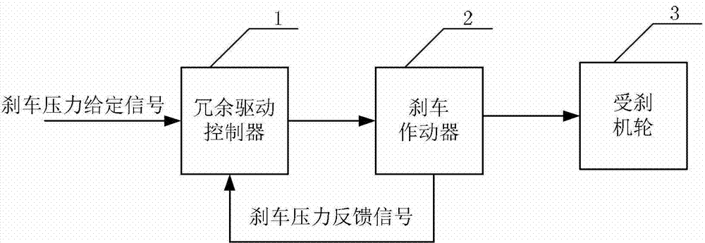
Fig. 1 is brake redundant drive apparatus structure.
Among the figure, 1-redundant drive controller, 2-braking action device, the 3-wheel of being stopped
Fig. 2 is the redundant drive controller architecture
Among the figure, 4-two margin brushless DC motors, 5-brake pressure feedback conditioning unit; The given receiving element of 6-brake pressure, 7-DSP unit, 8-current acquisition unit; 9-overcurrent protection auxiliary unit, 10-power-supply system unit, 11-CPLD unit; 12-buffer circuit unit, 13-power drive unit.
Fig. 3, two remaining driving device controls methods.
The specific embodiment
As shown in Figure 1, the present invention includes redundant drive controller 1, braking action device 2 and the wheel 3 of being stopped.Redundant drive controller 1 receives the given signal of brake pressure, through control method control, drives two margin brushless DC motors 4 work in the braking action device 2, makes the brake pressure that is applied on the wheel 3 of being stopped follow the given signal of brake pressure.In the present invention, will control power supply, driving power, machine winding, motor Hall element, pressure sensor, power drive unit and back up design.
Wherein, redundant drive controller 1 comprises the given receiving element in brake pressure feedback conditioning unit 5, brake pressure 6, DSP unit 7, CPLD unit 11, buffer circuit unit 12, power drive unit 13, current acquisition unit 8, overcurrent protection auxiliary unit 9 and power-supply system unit 13.(0~40mA) is converted into 0~3V voltage signal through resistance to the given receiving element 6 of brake pressure with the given signal of brake pressure; The AD port of input DSP unit 7; Carry out analogue to digital conversion, brake pressure feedback conditioning unit 5 is with brake pressure feedback signal (the two-way 0~20mV differential pressure signal that is recorded by two remaining pressure sensors) amplification filtering to 0~3V voltage signal, the AD port of input DSP unit 7; Carry out analogue to digital conversion; Regulate through control program, the task manager through DSP unit 7, output is the duty cycle signals of two 4 two windings of margin brushless DC motor of control respectively.CPLD unit 11 carries out logic operation with 4 liang of covers of duty cycle signals and two margin brushless DC motors hall signal; The modulation commutation signal of two windings runnings of two margin brushless DC motors 4 is controlled in output respectively; Through the buffer circuit unit 12 with power drive unit 13, two margin brushless DC motors 4 operations of control.At power drive unit 13, gather the bus current of two margin brushless DC motors 4, through overcurrent protection auxiliary unit 9; With bus current and predefined overcurrent threshold; If bus current is greater than predefined overcurrent threshold value, then over-current signal is low, if bus current is smaller or equal to predefined overcurrent threshold value; Then over-current signal is high, and over-current signal is sent in the DSP unit 7.When over current fault appearred in motor, it was low that DSP unit 7 detects over-current signal, then turn-offs duty cycle signals, thereby got rid of over current fault.Bus current and phase current that two margin brushless DC motor 4 windings on the power drive unit 13 are gathered in current acquisition unit 8, and with input DSP unit 7 after bus current and the phase current filtering.Power-supply system unit 10 receives two control power supplys; Through diode two power supplys are connected in parallel; To the given receiving element in brake pressure feedback conditioning unit 5, brake pressure 6, DSP unit 7, CPLD unit 11, buffer circuit unit 12, power drive unit 13, current acquisition unit 8,9 power supplies of overcurrent protection auxiliary unit; Power-supply system unit 10 receives two driving powers, gives power drive unit 13 power supplies.
Braking action device 2 is made up of two margin brushless DC electric motor units 4 and reductor and ball-screw.Wherein, The stator winding of two margin brushless DC motors 4 be two be enclosed within 30 ° of electric angles of mutual deviation on the space Y type bonded assembly winding constitute; Two cover windings are isolated from each other on electric, magnetic field coupling on the space, remaining each other each other, the shared PM rotor of two margin brushless DC motors.Every cover winding of two margin brushless DC motors has separately independently Hall element, and two cover Hall elements are remaining each other, closes to be called two remaining Hall elements.The signal that two remaining Hall elements send is called two remaining hall signals.
Control method of the present invention is:
The first step: gather the brake pressure feedback signal, and carry out the AD conversion.Got into for second step.
Second step: if | remaining 1 brake pressure feedback-remaining 2 brake pressures feedback | < predefined error threshold (in this model machine, predefined error threshold is 500N) then got into for the 7th step, otherwise got into for the 3rd step.
The 3rd step: if remaining 1 brake pressure feeds back greater than range maxim (15000N), or remaining 1 rudder face pressure feedback got into for the 4th step less than range minimum value (100N).Otherwise got into for the 5th step.
The 4th step: be diagnosed as remaining 1 pressure sensor failure, remaining 2 brake pressure values of feedback are composed to pressure feedback.Got into for the 8th step.
The 5th step: if remaining 2 brake pressures feed back greater than range maxim (15000N), or remaining 2 brake pressures feedback got into for the 6th step less than range minimum value (100N).Otherwise got into for the 7th step.
The 6th step: be diagnosed as remaining 2 pressure sensor failures, remaining 1 brake pressure value of feedback is composed to pressure feedback.Got into for the 8th step.
The 7th step: pressure feedback=(remaining 1 brake pressure feedback+remaining 2 brake pressures feedback)/2 got into for the 8th step.
The 8th step: gather two remaining Hall element signals.Got into for the 9th step.
The 9th step:, then got into for the tenth step, otherwise got into for the 11 step if remaining 1 hall signal is 000 or 111.
The tenth step: be diagnosed as remaining 1 Hall element fault.Got into for the 11 step.
The 11 step:, then got into for the 12 step, otherwise got into for the 13 step if remaining 2 hall signals are 000 or 111.
The 12 step: be diagnosed as remaining 2 Hall element faults.Got into for the 13 step.
The 13 step: gather each remaining winding bus current and phase current.Got into for 14 steps.
The 14 step: if remaining 1 winding bus current greater than predefined short circuit threshold value (in this model machine, predefined short circuit threshold value is 2A), then got into for the 15 step, otherwise got into for the 18 step.
The 15 step: remaining 1 short circuit counting machine adds 1.Got into for the 16 step.
The 16 step: if remaining 1 short circuit counting machine greater than predefined short circuit upper limit threshold (in this model machine, predefined short circuit upper limit threshold is 10), then got into for the 17 step, otherwise got into for the 18 step.
The 17 step: be diagnosed as remaining 1 short circuit in winding fault.Got into for the 22 step.
The 18 step: if remaining 2 winding bus currents greater than predefined short circuit threshold value (in this model machine, predefined short circuit threshold value is 2A), then got into for the 19 step, otherwise got into for the 22 step.
The 19 step: remaining 2 short circuit counting machines add 1.Got into for the 20 step.
The 20 step: if remaining 2 short circuit counting machines greater than predefined short circuit upper limit threshold (in this model machine, predefined short circuit upper limit threshold is 10), then got into for the 21 step, otherwise got into for the 22 step.
The 21 step: be diagnosed as remaining 2 short circuit in winding faults.Got into for the 22 step.
The 22 the step: if remaining 1 winding bus current greater than motor minimum working current lower limit (in this model machine; Be limited to 50mA under the motor minimum working current) or remaining 2 winding bus currents greater than motor minimum working current lower limit (in this model machine; Be limited to 50mA under the motor minimum working current); Then got into for the 23 step, otherwise got into for the 31 step.
The 23 step: if remaining 1 winding phase current less than predefined standard 0 digit current lower limit (in this model machine, being limited to 30mA under predefined standard 0 digit current), then getting into for the 24 step, otherwise got into for the 27 step.
The 24 step: the remaining 1 winding counting machine that opens circuit adds 1, gets into for the 25 step.
The 25 step: the value of counting machine then got into for the 26 step, otherwise got into for the 27 step greater than the predefined upper limit threshold that opens circuit (in this model machine, the predefined upper limit threshold that opens circuit is 10) if remaining 1 winding opens circuit.
The 26 step: be diagnosed as remaining 1 winding open circuit fault.Got into for the 31 step.
The 27 step: if remaining 2 winding phase currents less than predefined standard 0 digit current lower limit (in this model machine, being limited to 30mA under predefined standard 0 digit current), then getting into for the 28 step, otherwise got into for the 31 step.
The 28 step: the remaining 2 windings counting machine that opens circuit adds 1, gets into for the 29 step.
The 29 step: the value of counting machine then got into for the 30 step, otherwise got into for the 31 step greater than the predefined upper limit threshold that opens circuit (in this model machine, the predefined upper limit threshold that opens circuit is 10) if remaining 2 windings open circuit.
The 30 step: be diagnosed as remaining 2 winding open circuit faults.Got into for the 31 step.
The 31 step: gather the given signal of brake pressure, and carry out the AD conversion.Got into for the 32 step.
The 32 step: if the value of pressure ring counting machine then got into for the 33 step greater than pressure ring Ct value (in this model machine, the pressure ring Ct value is 1ms).Otherwise got into for the 34 step.
The 33 step: the pressure ring counter O reset, carry out pressure ring PID calculating according to brake pressure is given with the brake pressure feedback.Got into for the 34 step.
The 34 step: the value of pressure ring counting machine adds 1, gets into for the 35 step.
The 35 step: if remaining 1 short circuit in winding fault or remaining 1 winding open circuit fault or remaining 1 Hall element fault then got into for the 36 step.Otherwise got into for the 37 step.
The 36 step: remaining 1 dutycycle is changed to 0, and remaining 2 dutycycles are changed to predefined constant duty ratio (in this model machine, predefined constant duty ratio is 20%); Send the motor reverse signal, turn-off PID and interrupt, the time can the DSP unit CAP interrupt; The record motor counter-rotating number of turns; If the number of turns of motor counter-rotating during more than or equal to the preset fault number of turns (in this model machine, the preset fault number of turns is circle), stops motor.Get into the first step.
The 37 step: if remaining 2 short circuit in winding faults or remaining 2 winding open circuit faults or remaining 2 Hall element faults then got into for the 38 step.Otherwise got into for the 39 step.
The 38 step: remaining 2 dutycycles are changed to 0, and remaining 1 dutycycle is changed to predefined constant duty ratio (in this model machine, predefined constant duty ratio is 20%); Send the motor reverse signal, turn-off PID and interrupt, the time can the DSP unit CAP interrupt; The record motor counter-rotating number of turns; If the number of turns of motor counter-rotating during more than or equal to the preset fault number of turns (in this model machine, the preset fault number of turns is circle), stops motor.Get into the first step.
The 39 step: remaining 1 and given the half the of pressure ring output that be respectively of remaining 2 electric current loops; Be fed back to the bus current of remaining separately; Through the electric current loop PID computing of remaining separately, operation result is imported DSP task manager separately, produces the duty cycle signals of remaining 1 and remaining 2 respectively.Get into the first step.

Claims (3)

1.一种冗余驱动飞机电刹车,包括冗余驱动控制器、刹车作动器和受刹机轮,其特征在于:冗余驱动控制器部分接收刹车压力给定信号,驱动刹车作动器工作,使施加在受刹机轮上的刹车压力跟随刹车压力给定信号;其中,冗余驱动控制器部分包括刹车压力反馈调理单元、刹车压力给定接收单元、DSP单元、CPLD单元、隔离电路单元、功率驱动单元、电流采集单元、过流保护辅助单元和电源系统单元,刹车压力给定接收单元将刹车压力给定信号转化为电压信号,输入DSP单元,刹车压力反馈调理单元将双余度压力传感器测得的两路刹车压力反馈信号放大滤波后输入DSP单元,DSP单元的输出分别控制刹车作动器两个绕组的占空比信号,CPLD单元将占空比信号和刹车作动器两套霍尔信号进行逻辑运算,分别输出控制刹车作动器的两个绕组运转的调制换向信号,经隔离电路单元和功率驱动单元,控制刹车作动器运行,在功率驱动单元采集双余度无刷直流电机的母线电流,经过流保护辅助单元,将母线电流与预先设定的过流阈值相比较,若母线电流大于预先设定的过流阈值,则过流信号为低,若母线电流小于等于预先设定的过流阈值,则过流信号为高,将过流信号送入DSP单元中,当电机出现过流故障时,DSP单元检测过流信号为低,则关断占空比信号,电流采集单元采集功率驱动单元上双余度无刷直流电机绕组的母线电流和相电流,并将母线电流和相电流滤波后输入DSP单元,电源系统单元接收两个控制电源,经二极管将两个电源并联在一起,向刹车压力反馈调理单元、刹车压力给定接收单元、DSP单元、CPLD单元、隔离电路单元、功率驱动单元、电流采集单元、过流保护辅助单元供电,电源系统单元接收两个驱动电源,给功率驱动单元供电。1. A redundant drive aircraft electric brake, comprising a redundant drive controller, a brake actuator and a braked wheel, characterized in that: the redundant drive controller part receives a brake pressure given signal to drive the brake actuator Work, so that the brake pressure applied to the braked wheel follows the brake pressure given signal; wherein, the redundant drive controller part includes a brake pressure feedback conditioning unit, a brake pressure given receiving unit, a DSP unit, a CPLD unit, and an isolation circuit unit, power drive unit, current acquisition unit, overcurrent protection auxiliary unit and power supply system unit, the brake pressure given receiving unit converts the brake pressure given signal into a voltage signal, and inputs it into the DSP unit, and the brake pressure feedback conditioning unit converts the dual redundancy The two brake pressure feedback signals measured by the pressure sensor are amplified and filtered and input to the DSP unit. The output of the DSP unit controls the duty ratio signals of the two windings of the brake actuator respectively. The CPLD unit combines the duty ratio signal and the two windings of the brake actuator. The Hall signal is used for logical operation, and the modulation and commutation signals for controlling the operation of the two windings of the brake actuator are respectively output. After the isolation circuit unit and the power drive unit, the operation of the brake actuator is controlled, and the double redundancy is collected in the power drive unit. The bus current of the brushless DC motor passes through the current protection auxiliary unit, and compares the bus current with the preset over-current threshold. If the bus current is greater than the preset over-current threshold, the over-current signal is low. If the bus current If it is less than or equal to the preset over-current threshold, the over-current signal is high, and the over-current signal is sent to the DSP unit. When the motor has an over-current fault, the DSP unit detects that the over-current signal is low, and the duty cycle is turned off The signal and current acquisition unit collects the bus current and phase current of the double-redundant brushless DC motor winding on the power drive unit, and filters the bus current and phase current and then inputs them into the DSP unit. Two power supplies are connected in parallel to supply power to the brake pressure feedback conditioning unit, brake pressure setting receiving unit, DSP unit, CPLD unit, isolation circuit unit, power drive unit, current acquisition unit, overcurrent protection auxiliary unit, and the power system unit receives Two drive power supplies supply power to the power drive unit. 2.根据权利要求1所述的冗余驱动飞机电刹车,其特征在于:所述的刹车作动器采用双余度无刷直流电机,双余度无刷直流电机的定子绕组为两套在空间上互差30°电角度的Y型连接的绕组构成,两套绕组电气上彼此隔离、空间上磁场耦合,彼此互为余度,双余度无刷直流电机共用一个永磁体转子;双余度无刷直流电机的每套绕组有各自独立的霍尔传感器,两套霍尔传感器互为余度。2. The redundantly driven aircraft electric brake according to claim 1, characterized in that: the brake actuator adopts a dual-redundancy brushless DC motor, and the stator windings of the double-redundancy brushless DC motor are two sets of The two sets of windings are electrically isolated from each other, and the magnetic field is coupled in space, and they are mutually redundant. The double-redundant brushless DC motor shares a permanent magnet rotor; the double-redundant Each set of windings of the brushless DC motor has its own independent Hall sensor, and the two sets of Hall sensors are redundant to each other. 3.一种权利要求1所述冗余驱动飞机电刹车的控制方法,其特征在于包括下述步骤:3. A control method for redundantly driving an aircraft electric brake according to claim 1, characterized in that it comprises the following steps: 第一步:采集两路刹车压力反馈信号,并进行AD转化;Step 1: Collect two brake pressure feedback signals and perform AD conversion; 第二步:若两路刹车压力反馈信号小于预先设定的误差阈值,则进入第四步,否则进入第三步;Step 2: If the two brake pressure feedback signals are less than the preset error threshold, go to step 4, otherwise go to step 3; 第三步:若一路刹车压力反馈信号大于压力传感器的量程最大值,或小于其量程最小值,则诊断该路压力传感器故障,将另一路压力传感器的刹车压力反馈信号赋值给压力反馈,进入第五步,否则进入第四步;Step 3: If the brake pressure feedback signal of one road is greater than the maximum value of the pressure sensor’s range, or smaller than the minimum value of its range, diagnose the failure of the pressure sensor of this road, assign the brake pressure feedback signal of the other pressure sensor to the pressure feedback, and enter the first step Five steps, otherwise go to the fourth step; 第四步:压力反馈等于两路刹车压力反馈信号之和除以二;Step 4: The pressure feedback is equal to the sum of the two brake pressure feedback signals divided by two; 第五步:采集双余度霍尔传感器信号,若一路霍尔传感器信号为000或111,则诊断该路霍尔传感器故障,否则进入第六步;Step 5: Collect the dual-redundancy Hall sensor signal. If one Hall sensor signal is 000 or 111, then diagnose the Hall sensor fault, otherwise enter the sixth step; 第六步:采集各余度绕组母线电流和相电流;Step 6: Collect the bus current and phase current of each redundant winding; 第七步:若一路绕组母线电流大于预先设定的短路阈值,则开始短路计时,若短路计时大于预先设定的短路上限阈值,则诊断该路绕组为短路故障,进入第十步;若一路绕组母线电流大于电机最小工作电流,且小于预先设定的标准0位电流下限,则开始断路计时,若断路计时大于预先设定的断路上限阈值,则诊断该路绕组为断路故障,进入第十步;否则进入第八步;Step 7: If the bus current of one winding is greater than the preset short-circuit threshold, start the short-circuit timing. If the short-circuit timing is greater than the preset short-circuit upper threshold, diagnose the winding as a short-circuit fault and enter the tenth step; If the winding bus current is greater than the minimum operating current of the motor and less than the preset standard 0-bit current lower limit, the circuit breaker timing will start. If the circuit breaker timer is greater than the preset circuit breaker upper threshold, the winding will be diagnosed as an open circuit fault and enter the tenth stage. step; otherwise go to the eighth step; 第八步:采集刹车压力给定信号,并进行AD转化;Step 8: Collect the brake pressure given signal and perform AD conversion; 第九步:若压力环计数器的值大于压力环周期阈值,则将压力环计数器清零,根据刹车压力给定和刹车压力反馈进行压力环PID计算,然后将压力环计数器的值加1;否则直接将压力环计数器的值加1;Step 9: If the value of the pressure loop counter is greater than the pressure loop cycle threshold, clear the pressure loop counter, perform pressure loop PID calculations according to the given brake pressure and brake pressure feedback, and then add 1 to the value of the pressure loop counter; otherwise Directly add 1 to the value of the pressure ring counter; 第十步:若一路绕组短路故障或断路故障或对应的该路霍尔传感器故障,则将该路占空比置为0,将另一路占空比置为预先设定的恒定占空比,发出电机反转信号,记录电机反转圈数,若电机反转的圈数大于等于预设的故障圈数时,停止电机,返回第一步,否则进入第十一步;Step 10: If one winding short-circuit fault or open circuit fault or the corresponding Hall sensor fault, then set the duty cycle of this road to 0, and set the duty cycle of the other road to a preset constant duty cycle, Send the motor reverse signal, record the number of motor reverse rotation, if the motor reverse rotation is greater than or equal to the preset failure number of circles, stop the motor, return to the first step, otherwise enter the eleventh step; 第十一步:两路电流环给定分别为压力环输出的一半,反馈为各自的母线电流,经过各自的电流环PID运算,运算结果输入DSP,分别产生各自的占空比信号,返回第一步。Step 11: The two current loops are given as half of the output of the pressure loop, and the feedback is the respective bus current. After the respective current loop PID calculations, the calculation results are input to the DSP to generate their respective duty cycle signals, and return to the first step.
CN201210176423.XA 2012-05-31 2012-05-31 Redundant driving electric brake of airplane and control method for redundant driving electric brake Expired - Fee Related CN102700530B (en)

Priority Applications (1)

Application Number Priority Date Filing Date Title
CN201210176423.XA CN102700530B (en) 2012-05-31 2012-05-31 Redundant driving electric brake of airplane and control method for redundant driving electric brake

Applications Claiming Priority (1)

Application Number Priority Date Filing Date Title
CN201210176423.XA CN102700530B (en) 2012-05-31 2012-05-31 Redundant driving electric brake of airplane and control method for redundant driving electric brake

Publications (2)

Publication Number Publication Date
CN102700530A true CN102700530A (en) 2012-10-03
CN102700530B CN102700530B (en) 2014-11-05

Family

ID=46893695

Family Applications (1)

Application Number Title Priority Date Filing Date
CN201210176423.XA Expired - Fee Related CN102700530B (en) 2012-05-31 2012-05-31 Redundant driving electric brake of airplane and control method for redundant driving electric brake

Country Status (1)

Country Link
CN (1) CN102700530B (en)

Cited By (12)

* Cited by examiner, † Cited by third party
Publication number Priority date Publication date Assignee Title
CN102700542A (en) * 2012-05-31 2012-10-03 西北工业大学 Dual-redundancy electric brake device of airplane and control method for dual-redundancy electric brake device
CN103786704A (en) * 2014-01-26 2014-05-14 北京航空航天大学 Dissimilar redundancy airplane braking system and control method thereof
CN103929179A (en) * 2014-04-11 2014-07-16 西北工业大学 Anti-interference method for sampling of aircraft electric braking system
CN104617847A (en) * 2015-02-26 2015-05-13 北京精密机电控制设备研究所 Fault-tolerant electro-mechanical actuating system
CN104787311A (en) * 2015-04-08 2015-07-22 西北工业大学 All-electric aircraft brake system and aircraft electric brake redundancy control method
EP2965962A3 (en) * 2014-07-07 2016-04-27 Goodrich Corporation Apparatus and system for power distribution to brake systems
CN107659147A (en) * 2016-07-25 2018-02-02 意法半导体股份有限公司 For the output voltage control under the overcurrent condition of switch converters
CN108897269A (en) * 2018-07-09 2018-11-27 西北工业大学 Electrical Break System of Aircraft pressure sensor fault tolerant control method
CN112061099A (en) * 2019-05-25 2020-12-11 罗伯特·博世有限公司 Electrohydraulic power-assisted vehicle brake system for autonomously traveling land vehicles
CN113734427A (en) * 2021-07-28 2021-12-03 北京精密机电控制设备研究所 Unmanned aerial vehicle dual-redundancy front wheel turning servo system
CN115551751A (en) * 2020-05-12 2022-12-30 赛峰起落架系统公司 Distributed Architecture of Aircraft Braking System
CN118163942A (en) * 2024-04-07 2024-06-11 北京航空航天大学 A self-feeding brake controller based on high-speed DSP

Citations (4)

* Cited by examiner, † Cited by third party
Publication number Priority date Publication date Assignee Title
US6954692B2 (en) * 2003-12-01 2005-10-11 Messier-Bugatti Method of managing brake system architecture for an airplane fitted with brakes having electromechanical actuators, and an architecture applying the method
US20080030069A1 (en) * 2006-08-04 2008-02-07 Griffith T Todd Aircraft electrical brake control system architecture
CN202218058U (en) * 2011-09-08 2012-05-09 西安航空制动科技有限公司 A redundant power supply system
CN202608760U (en) * 2012-05-31 2012-12-19 西北工业大学 Airplane double-redundancy electric-brake device

Patent Citations (4)

* Cited by examiner, † Cited by third party
Publication number Priority date Publication date Assignee Title
US6954692B2 (en) * 2003-12-01 2005-10-11 Messier-Bugatti Method of managing brake system architecture for an airplane fitted with brakes having electromechanical actuators, and an architecture applying the method
US20080030069A1 (en) * 2006-08-04 2008-02-07 Griffith T Todd Aircraft electrical brake control system architecture
CN202218058U (en) * 2011-09-08 2012-05-09 西安航空制动科技有限公司 A redundant power supply system
CN202608760U (en) * 2012-05-31 2012-12-19 西北工业大学 Airplane double-redundancy electric-brake device

Non-Patent Citations (2)

* Cited by examiner, † Cited by third party
Title
蔡文举: "飞机全电防滑刹车控制器", 《工程科技II辑》 *
高金行,金兴源,戴志勇,曹杨: "飞机刹车用双余度无刷直流电动机的研究", 《微电机》 *

Cited By (17)

* Cited by examiner, † Cited by third party
Publication number Priority date Publication date Assignee Title
CN102700542A (en) * 2012-05-31 2012-10-03 西北工业大学 Dual-redundancy electric brake device of airplane and control method for dual-redundancy electric brake device
CN102700542B (en) * 2012-05-31 2014-06-11 西北工业大学 Dual-redundancy electric brake device of airplane and control method for dual-redundancy electric brake device
CN103786704A (en) * 2014-01-26 2014-05-14 北京航空航天大学 Dissimilar redundancy airplane braking system and control method thereof
CN103786704B (en) * 2014-01-26 2016-03-30 北京航空航天大学 Aircraft dissimilar redundancy brake system and control method thereof
CN103929179A (en) * 2014-04-11 2014-07-16 西北工业大学 Anti-interference method for sampling of aircraft electric braking system
CN103929179B (en) * 2014-04-11 2017-07-04 西北工业大学 A kind of Electric Brake System of Aircraft systematic sampling anti-interference method
EP2965962A3 (en) * 2014-07-07 2016-04-27 Goodrich Corporation Apparatus and system for power distribution to brake systems
CN104617847A (en) * 2015-02-26 2015-05-13 北京精密机电控制设备研究所 Fault-tolerant electro-mechanical actuating system
CN104787311B (en) * 2015-04-08 2016-09-21 西北工业大学 Aircraft all-electric braking system and aircraft electric braking margin control method
CN104787311A (en) * 2015-04-08 2015-07-22 西北工业大学 All-electric aircraft brake system and aircraft electric brake redundancy control method
CN107659147A (en) * 2016-07-25 2018-02-02 意法半导体股份有限公司 For the output voltage control under the overcurrent condition of switch converters
CN107659147B (en) * 2016-07-25 2020-03-24 意法半导体股份有限公司 Output voltage control in over-current condition for switching converter
CN108897269A (en) * 2018-07-09 2018-11-27 西北工业大学 Electrical Break System of Aircraft pressure sensor fault tolerant control method
CN112061099A (en) * 2019-05-25 2020-12-11 罗伯特·博世有限公司 Electrohydraulic power-assisted vehicle brake system for autonomously traveling land vehicles
CN115551751A (en) * 2020-05-12 2022-12-30 赛峰起落架系统公司 Distributed Architecture of Aircraft Braking System
CN113734427A (en) * 2021-07-28 2021-12-03 北京精密机电控制设备研究所 Unmanned aerial vehicle dual-redundancy front wheel turning servo system
CN118163942A (en) * 2024-04-07 2024-06-11 北京航空航天大学 A self-feeding brake controller based on high-speed DSP

Also Published As

Publication number Publication date
CN102700530B (en) 2014-11-05

Similar Documents

Publication Publication Date Title
CN102700530A (en) Redundant driving electric brake of airplane and control method for redundant driving electric brake
CN102700542B (en) Dual-redundancy electric brake device of airplane and control method for dual-redundancy electric brake device
CN104787311B (en) Aircraft all-electric braking system and aircraft electric braking margin control method
CN202608760U (en) Airplane double-redundancy electric-brake device
CN102947177B (en) For the power supply of actuator and control equipment, corresponding actuating assembly and the aircraft including this equipment
CN101624969B (en) Redundancy control system and redundancy control method for wind power generation propeller change
CN104229126B (en) A kind of highly reliable landing gear control system
CN202632110U (en) Dual-redundancy steering engine system
CN104590550B (en) A kind of highly reliable dual redundant electric steering engine control device
CN106227099A (en) A kind of cooperative control system of double winding permagnetic synchronous motor
CN101667805A (en) Six-phase permanent magnet fault-tolerant motor control system
CN104579029A (en) Tri-redundancy brushless DC servo drive controller
CN109823522B (en) Multi-redundancy undercarriage electric retraction controller
CN106058285B (en) A kind of unmanned plane activation of fuel cell control system and control method
CN104648660A (en) Airplane dual-redundancy digital type undercarriage retraction/extension controller
CN202276306U (en) Binary-channel redundancy brushless direct current motor driver
JP2023511516A (en) Motor control system and motor control device
CN111976968A (en) Control circuit and control method for electric turning mechanism of front wheel of airplane
CN110963025A (en) Aircraft brake system architecture
CN105000172A (en) Launch and recovery electrical control system of aircraft landing gear
CN105375835A (en) Device and method of safety protection of photo-electricity telescope
CN104787024A (en) Powering-on self-detecting method for electrical brake
CN219760877U (en) Centralized control platform switching power supply system
CN110971148A (en) Braking device and method of motor control system
CN211089504U (en) Braking device of motor control system

Legal Events

Date Code Title Description
C06 Publication
PB01 Publication
C10 Entry into substantive examination
SE01 Entry into force of request for substantive examination
C14 Grant of patent or utility model
GR01 Patent grant
CF01 Termination of patent right due to non-payment of annual fee

Granted publication date: 20141105

Termination date: 20150531

EXPY Termination of patent right or utility model