CN102712310A - Reservoir tank and brake device employing same - Google Patents
Reservoir tank and brake device employing same Download PDFInfo
- Publication number
- CN102712310A CN102712310A CN2011800073011A CN201180007301A CN102712310A CN 102712310 A CN102712310 A CN 102712310A CN 2011800073011 A CN2011800073011 A CN 2011800073011A CN 201180007301 A CN201180007301 A CN 201180007301A CN 102712310 A CN102712310 A CN 102712310A
- Authority
- CN
- China
- Prior art keywords
- magnet
- float
- working fluid
- liquid level
- storage tank
- Prior art date
- Legal status (The legal status is an assumption and is not a legal conclusion. Google has not performed a legal analysis and makes no representation as to the accuracy of the status listed.)
- Granted
Links
Images




Classifications
-
- B—PERFORMING OPERATIONS; TRANSPORTING
- B60—VEHICLES IN GENERAL
- B60T—VEHICLE BRAKE CONTROL SYSTEMS OR PARTS THEREOF; BRAKE CONTROL SYSTEMS OR PARTS THEREOF, IN GENERAL; ARRANGEMENT OF BRAKING ELEMENTS ON VEHICLES IN GENERAL; PORTABLE DEVICES FOR PREVENTING UNWANTED MOVEMENT OF VEHICLES; VEHICLE MODIFICATIONS TO FACILITATE COOLING OF BRAKES
- B60T11/00—Transmitting braking action from initiating means to ultimate brake actuator without power assistance or drive or where such assistance or drive is irrelevant
- B60T11/10—Transmitting braking action from initiating means to ultimate brake actuator without power assistance or drive or where such assistance or drive is irrelevant transmitting by fluid means, e.g. hydraulic
- B60T11/16—Master control, e.g. master cylinders
- B60T11/22—Master control, e.g. master cylinders characterised by being integral with reservoir
-
- B—PERFORMING OPERATIONS; TRANSPORTING
- B60—VEHICLES IN GENERAL
- B60T—VEHICLE BRAKE CONTROL SYSTEMS OR PARTS THEREOF; BRAKE CONTROL SYSTEMS OR PARTS THEREOF, IN GENERAL; ARRANGEMENT OF BRAKING ELEMENTS ON VEHICLES IN GENERAL; PORTABLE DEVICES FOR PREVENTING UNWANTED MOVEMENT OF VEHICLES; VEHICLE MODIFICATIONS TO FACILITATE COOLING OF BRAKES
- B60T11/00—Transmitting braking action from initiating means to ultimate brake actuator without power assistance or drive or where such assistance or drive is irrelevant
- B60T11/10—Transmitting braking action from initiating means to ultimate brake actuator without power assistance or drive or where such assistance or drive is irrelevant transmitting by fluid means, e.g. hydraulic
- B60T11/26—Reservoirs
-
- B—PERFORMING OPERATIONS; TRANSPORTING
- B60—VEHICLES IN GENERAL
- B60T—VEHICLE BRAKE CONTROL SYSTEMS OR PARTS THEREOF; BRAKE CONTROL SYSTEMS OR PARTS THEREOF, IN GENERAL; ARRANGEMENT OF BRAKING ELEMENTS ON VEHICLES IN GENERAL; PORTABLE DEVICES FOR PREVENTING UNWANTED MOVEMENT OF VEHICLES; VEHICLE MODIFICATIONS TO FACILITATE COOLING OF BRAKES
- B60T17/00—Component parts, details, or accessories of power brake systems not covered by groups B60T8/00, B60T13/00 or B60T15/00, or presenting other characteristic features
- B60T17/18—Safety devices; Monitoring
- B60T17/22—Devices for monitoring or checking brake systems; Signal devices
- B60T17/225—Devices for monitoring or checking brake systems; Signal devices brake fluid level indicators
-
- H—ELECTRICITY
- H01—ELECTRIC ELEMENTS
- H01H—ELECTRIC SWITCHES; RELAYS; SELECTORS; EMERGENCY PROTECTIVE DEVICES
- H01H36/00—Switches actuated by change of magnetic field or of electric field, e.g. by change of relative position of magnet and switch, by shielding
- H01H36/02—Switches actuated by change of magnetic field or of electric field, e.g. by change of relative position of magnet and switch, by shielding actuated by movement of a float carrying a magnet
Landscapes
- Engineering & Computer Science (AREA)
- Transportation (AREA)
- Mechanical Engineering (AREA)
- Transmission Of Braking Force In Braking Systems (AREA)
Abstract
Description
技术领域 technical field
本发明涉及利用了油压等液压的液压制动装置、液压离合装置所使用的,储存工作液的贮存箱的技术领域及使用该贮存箱的制动装置的技术领域。 The present invention relates to the technical field of a storage tank for storing working fluid used in a hydraulic brake device and a hydraulic clutch device using hydraulic pressure such as oil pressure, and to the technical field of a brake device using the storage tank.
背景技术 Background technique
以往,在汽车等车辆中,有的车辆采用利用了液压的液压制动装置、液压离合装置。这些液压制动装置、液压离合装置使用产生液压的主缸、及储存向该主缸供给的工作液的贮存箱。 Conventionally, vehicles such as automobiles employ hydraulic brake devices and hydraulic clutch devices using hydraulic pressure. These hydraulic brake devices and hydraulic clutch devices use a master cylinder that generates hydraulic pressure and a storage tank that stores hydraulic fluid supplied to the master cylinder.
主缸为了在需要液压时产生液压,需要在贮存箱内储存有预定液量的工作液。因此,一般在贮存箱设有液量检测传感器,若贮存箱内的液量低于预定液量,则该液量检测传感器对其进行检测,并在液量显示装置显示。利用该液量显示装置的显示,向贮存箱内补给工作液,确保贮存箱内的液量为预定液量以上。 In order to generate hydraulic pressure when the hydraulic pressure is required, the master cylinder needs to store a predetermined amount of hydraulic fluid in the storage tank. Therefore, a liquid volume detection sensor is generally provided in the storage tank, and if the liquid volume in the storage tank is lower than a predetermined liquid volume, the liquid volume detection sensor will detect it and display it on the liquid volume display device. Using the display of the liquid amount display device, the working fluid is supplied into the storage tank, and the liquid amount in the storage tank is ensured to be equal to or greater than a predetermined liquid amount.
作为以往的贮存箱的液量检测传感器,已知如下的液量检测传感器,在贮存箱的上表面设置常闭型的行程开关,并且在根据贮存箱内的工作液的液面的高度而上下移动的浮子上设有磁体(例如参照专利文献1)。 As a conventional liquid level detection sensor for a storage tank, there is known a liquid level detection sensor in which a normally closed limit switch is provided on the upper surface of the storage tank, and the limit switch is moved up and down according to the height of the liquid level of the working fluid in the storage tank. A magnet is provided on the moving float (for example, refer to Patent Document 1).
在该专利文献1所公开的液量检测传感器中,浮子被从贮存箱的上端内表面垂下的引导件引导而上下移动。而且,在贮存箱内的工作液的液面较高时,浮子向上移动,磁体接近行程开关,行程开关因其磁力而断开(off)。据此,警告灯熄灯。另外,在贮存箱内的工作液的液面较低为熄灯液面以下时,浮子向下移动,磁体离开行程开关,其磁力变得不影响行程开关,行程开关因自力而接通(on)。据此,警告灯点亮。 In the liquid amount detection sensor disclosed in Patent Document 1, the float moves up and down while being guided by a guide hanging down from the upper end inner surface of the storage tank. And, when the liquid level of the working fluid in the storage tank is high, the float moves upward, the magnet approaches the travel switch, and the travel switch is turned off by its magnetic force. Accordingly, the warning light turns off. In addition, when the liquid level of the working fluid in the storage tank is lower than the light-off liquid level, the float moves downward, and the magnet moves away from the limit switch, and its magnetic force does not affect the limit switch, and the limit switch is turned on by itself. . Accordingly, the warning light comes on.
专利文献1:日本特表2006-519728号公报。 Patent Document 1: Japanese PCT Publication No. 2006-519728.
发明内容 Contents of the invention
但是,在专利文献1所公开的贮存箱的液量检测传感器中,由于磁体设在浮子的上下方向的大致中心位置,因此浮子的上下方向的尺寸被设定得比较小。然而,若浮子的上下方向的尺寸较小,则浮子由于车辆倾斜移动时等的液面变动而倾斜,浮子与引导件之间的摩擦阻力增大,浮子容易卡在引导件上。因此,认为浮子可能难以与液面的变化联动地顺畅且可靠地上下移动。 However, in the liquid amount detection sensor for the storage tank disclosed in Patent Document 1, since the magnet is provided at the substantially center position in the vertical direction of the float, the vertical dimension of the float is set relatively small. However, if the vertical dimension of the float is small, the float tilts due to liquid level fluctuations such as when the vehicle is tilted, increasing the frictional resistance between the float and the guide, and the float tends to get stuck on the guide. Therefore, it may be difficult for the float to move up and down smoothly and reliably in conjunction with changes in the liquid level.
因此,考虑增大浮子的上下方向的尺寸,若但单纯增大浮子的上下方向的尺寸,则磁体会远离行程开关。因此,为了在熄灯液面利用磁体使行程开关接通断开,即提高行程开关的工作可靠性,需要使熄灯液面接近行程开关。但存在的问题是:使熄灯液面接近行程开关时,难以将贮存箱的工作液的储存容量设定得较大。若为了将贮存箱的工作液的储存容量设定得较大,而使熄灯液面远离行程开关,则在行程开关的接通断开时磁体也会大幅远离行程开关。因此,为了使行程开关可靠地接通断开,必须增大磁体的磁力,成本较高。 Therefore, considering increasing the vertical dimension of the float, if simply increasing the vertical dimension of the float, the magnet will move away from the travel switch. Therefore, in order to use a magnet to turn on and off the travel switch at the light-off liquid level, that is, to improve the working reliability of the travel switch, it is necessary to make the light-off liquid level close to the travel switch. However, there is a problem that it is difficult to set the storage capacity of the working fluid in the storage tank to be large when the light-off liquid level approaches the travel switch. If the light-off liquid level is kept away from the travel switch in order to increase the storage capacity of the working fluid in the storage tank, the magnet is also largely separated from the travel switch when the travel switch is turned on and off. Therefore, in order to reliably turn on and off the travel switch, it is necessary to increase the magnetic force of the magnet, and the cost is high.
本发明是鉴于这样的情况而完成的,其目的在于提供一种廉价的贮存箱及使用该贮存箱的制动装置,该贮存箱能够使浮子可靠地上下移动,使行程开关稳定进行工作,使熄灯液面进一步远离行程开关。 The present invention is made in view of such circumstances, and its object is to provide an inexpensive storage box and a braking device using the storage box, which can reliably move the float up and down, make the limit switch work stably, and The light-off liquid level is further away from the travel switch.
为解决上述问题,本发明的贮存箱包括对储存的工作液进行检测的液量检测部,所述液量检测部具有行程开关和浮子,所述行程开关在储存的工作液的液面为预定液面以下时接通,并且在所述液面高于预定液面时断开,所述浮子设有对所述行程开关进行接通断开的磁体,并且根据所述工作液的液面而上下移动,所述行程开关设在所述磁体的上方,其特征在于,所述浮子具有浮子主体、从所述浮子主体向上方突出设置的磁体支柱、设在所述磁体支柱的上端并支撑所述磁体的磁体支撑部、以及增强所述磁体支柱的支柱增强部件。 In order to solve the above problems, the storage tank of the present invention includes a liquid volume detection unit for detecting the stored working fluid, the liquid volume detection unit has a travel switch and a float, and the travel switch is set at a predetermined level when the liquid level of the stored working fluid is It is turned on when the liquid level is below the predetermined liquid level, and it is turned off when the liquid level is higher than the predetermined liquid level. Moving up and down, the travel switch is arranged above the magnet, and it is characterized in that the float has a float body, a magnet pillar protruding upward from the float body, and is arranged on the upper end of the magnet pillar and supports the magnet pillar. A magnet support portion of the magnet, and a post reinforcing member for reinforcing the magnet post.
另外,本发明的贮存箱的特征在于,所述浮子由树脂一体成形而形成,所述支柱增强部件具有用于在金属模脱模时取出金属模的取出斜面。 In addition, the storage tank according to the present invention is characterized in that the float is integrally formed of resin, and the pillar reinforcing member has a take-out slope for taking out the mold when the mold is released.
进一步,本发明的贮存箱的特征在于,所述取出斜面形成于在填充树脂时不阻碍所述树脂的流动的方向。 Further, the storage tank of the present invention is characterized in that the take-out slope is formed in a direction that does not hinder the flow of the resin when the resin is filled.
进一步地,本发明的贮存箱包括对储存的工作液进行检测的液量检测部,所述液量检测部具有行程开关和浮子,所述行程开关在储存的工作液的液面为预定液面以下时接通,并且在所述液面高于预定液面时断开,所述浮子设有对所述行程开关进行接通断开的磁体,并且根据所述工作液的液面而上下移动,所述行程开关设在所述磁体的上方,其特征在于,所述浮子具有浮子主体、从所述浮子主体向上方突出设置的磁体支柱、以及设在所述磁体支柱的上端并支撑所述磁体的磁体支撑部,所述磁体支柱形成为从所述磁体的长边方向观察的梯形。 Furthermore, the storage tank of the present invention includes a liquid volume detection unit for detecting the stored working fluid, the liquid volume detection unit has a travel switch and a float, and the travel switch is set when the liquid level of the stored working fluid is a predetermined liquid level It is turned on when the temperature is below, and it is turned off when the liquid level is higher than the predetermined liquid level. The float is provided with a magnet for turning on and off the travel switch, and moves up and down according to the liquid level of the working fluid. , the travel switch is arranged above the magnet, and it is characterized in that the float has a float body, a magnet strut protruding upward from the float body, and an upper end of the magnet strut that supports the In the magnet supporting part of the magnet, the magnet support is formed in a trapezoidal shape viewed from the long side direction of the magnet.
进一步,本发明的制动装置至少包括储存工作液的贮存箱、被供给所述贮存箱内的工作液并且在工作时产生制动压的主缸、以及以来自所述主缸的液压进行工作的制动缸,其特征在于,所述贮存箱是上述本发明的贮存箱中的任意一个。 Further, the brake device of the present invention includes at least a storage tank for storing working fluid, a master cylinder that is supplied with the working fluid in the storage tank and generates brake pressure during operation, and operates with the hydraulic pressure from the master cylinder. The brake cylinder is characterized in that the storage tank is any one of the above-mentioned storage tanks of the present invention.
根据这样构成的本发明的贮存箱,将行程开关配设在磁体的上方,并且利用磁体支柱将该磁体支撑在浮子的上端,进一步边用第一引导件和第二引导件来引导浮子边使其上下移动。这样,通过利用磁体支柱将磁体支撑在浮子的上端,能够增大浮子的上下方向尺寸。所以,能够使浮子根据工作液的液面顺畅且可靠地上下移动。 According to the storage tank of the present invention constituted in this way, the travel switch is arranged above the magnet, and the magnet is supported on the upper end of the float by the magnet support, and the float is further guided by the first guide and the second guide. It moves up and down. In this way, by supporting the magnet on the upper end of the float with the magnet support, the vertical dimension of the float can be increased. Therefore, the float can be moved up and down smoothly and reliably in accordance with the liquid level of the working fluid.
特别是在磁体支柱上设有增强肋。通过利用这些增强肋来增强磁体支柱,磁体支柱的强度增大。所以,即使磁体支柱受到外力也能够抑制磁体支柱的弯曲。所以,能够进一步有效提高浮子的工作性。据此,能够使磁体以稳定的姿势进行上下移动,能够使行程开关稳定工作。 In particular, reinforcement ribs are provided on the magnet support. By reinforcing the magnet support with these reinforcing ribs, the strength of the magnet support is increased. Therefore, even if the magnet support receives an external force, it is possible to suppress the bending of the magnet support. Therefore, the workability of the float can be further effectively improved. Accordingly, the magnet can be moved up and down in a stable posture, and the limit switch can be stably operated.
另外,增强肋具有取出斜面,其角度为使其厚度向前端减小。据此,在金属模脱模时金属模滑动之际,能够抑制磁体支柱的变形弯曲,并且即使设有增强肋,也能够抑制浮子成形收缩。所以,由于抑制了浮子的变形,因此,能够进一步有效提高浮子的工作性。而且,由于增强肋具有如上所述的取出斜面,因此对于贮存箱内的工作液在车辆前后方向的移动,能够减小增强肋的阻力。据此,即使工作液在车辆前后方向移动,也能使浮子主体的姿势稳定,能够抑制液面下降时(工作液减少时)的行程开关的误动作。进一步,通过将增强肋的取出斜面形成于在填充树脂时不阻碍树脂的流动的方向,能够提高树脂的填充性,能够降低树脂的填充不足或者树脂的填充不良。 In addition, the reinforcing rib has an extraction slope at an angle such that its thickness decreases toward the front end. Accordingly, when the mold slides when the mold is released, deformation and bending of the magnet support can be suppressed, and molding shrinkage of the float can be suppressed even if reinforcing ribs are provided. Therefore, since the deformation of the float is suppressed, the workability of the float can be further effectively improved. Furthermore, since the reinforcement rib has the extraction slope as described above, it is possible to reduce the resistance of the reinforcement rib to the movement of the working fluid in the storage tank in the vehicle front-rear direction. Accordingly, even if the hydraulic fluid moves in the vehicle front-rear direction, the posture of the float body can be stabilized, and malfunction of the limit switch can be suppressed when the liquid level drops (when the hydraulic fluid decreases). Furthermore, by forming the take-out slope of the reinforcing rib in a direction that does not hinder the flow of the resin when filling the resin, the filling performance of the resin can be improved, and insufficient filling of the resin or poor filling of the resin can be reduced.
进一步地,由于将磁体设在浮子的上端,因此能够使磁体接近行程开关。据此,能够使熄灯液面远离行程开关。所以,能够将贮存箱的工作液的储存容量设定得更大。而且,即使将熄灯液面远离行程开关,浮子的熄灯液面处的磁体的位置也能够进一步接近行程开关。据此,能够提高行程开关的工作可靠性。其结果是,能够减小磁体的磁力,能够降低成本。 Furthermore, since the magnet is provided on the upper end of the float, the magnet can be brought close to the travel switch. Accordingly, it is possible to keep the light-off liquid level away from the limit switch. Therefore, the storage capacity of the hydraulic fluid in the storage tank can be set larger. Moreover, even if the light-off liquid level is far away from the travel switch, the position of the magnet at the light-off liquid level of the float can be further approached to the travel switch. Accordingly, the operational reliability of the travel switch can be improved. As a result, the magnetic force of the magnet can be reduced, and the cost can be reduced.
进一步地,由于用磁体支柱构成浮子的上方部,因此可以减小磁体支柱的工作液的受压面积。据此,即使例如由于车辆的急制动或急转弯等使贮存箱内的工作液急剧移动,也能够抑制由于移动的工作液而施加在磁体支柱的力。所以,能够减小因工作液的急剧的移动对浮子的影响,能够进一步有效防止行程开关的误动作,能够更可靠地防止警告灯的误点亮。 Furthermore, since the upper part of the float is constituted by the magnet support, the pressure receiving area of the working fluid of the magnet support can be reduced. Accordingly, even if the hydraulic fluid in the storage tank moves suddenly due to, for example, sudden braking or sharp turning of the vehicle, the force applied to the magnet post by the moving hydraulic fluid can be suppressed. Therefore, it is possible to reduce the influence on the float due to the rapid movement of the working fluid, to further effectively prevent the malfunction of the limit switch, and to more reliably prevent the malfunction of the warning lamp.
进一步地,通过对磁体支柱的长度、直径进行各种变更,能够对浮子室内的体积进行各种变更。所以,对于根据装载贮存箱的车辆的车种而各不相同的贮存箱,能够更灵活且可靠地进行对应。 Furthermore, various changes can be made to the volume of the float chamber by making various changes to the length and diameter of the magnet support. Therefore, it is possible to more flexibly and reliably cope with different storage tanks depending on the model of the vehicle on which the storage tank is mounted.
如上所述,根据本发明的贮存箱,由于贮存箱的浮子及磁体能够更可靠地上下移动,因此能够更有效防止液量检测部的误动作导致警告灯的误点亮。 As described above, according to the storage tank of the present invention, since the float and the magnet of the storage tank can move up and down more reliably, it is possible to more effectively prevent the warning lamp from being turned on incorrectly due to a malfunction of the liquid amount detection unit.
另一方面,根据使用了本发明的贮存箱的制动装置,由于利用液量检测部能够更可靠地检测贮存箱内的工作液的液量,因此能够更可靠地进行制动工作。 On the other hand, according to the brake device using the reservoir tank of the present invention, since the fluid volume detection unit can more reliably detect the fluid volume of the hydraulic fluid in the storage tank, the brake operation can be performed more reliably.
附图说明 Description of drawings
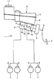
图1是示意包括本发明所涉及的贮存箱的实施方式的第一例的制动装置的图。 FIG. 1 is a diagram schematically showing a braking device including a first example of an embodiment of a storage tank according to the present invention.
图2(a)是示出局部地切开第一例的贮存箱的图,(b)是该第一例的贮存箱的长边方向的纵向剖视图。 Fig. 2(a) is a partially cutaway view of the storage box of the first example, and (b) is a longitudinal cross-sectional view of the storage box of the first example in the longitudinal direction.
图3(a)是沿着图2(a)的IIIA-IIIA线的剖视图,(b)是从下方观察引导件的图,(c)是沿着(a)的IIIC-IIIC线的剖视图,(d)是沿着(a)的IIID-IIID线的剖视图。 Fig. 3(a) is a cross-sectional view along line IIIA-IIIA of Fig. 2(a), (b) is a view of the guide viewed from below, and (c) is a cross-sectional view along line IIIC-IIIC of (a), (d) is a cross-sectional view along line IIID-IIID of (a).
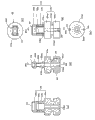
图4示出第一例的浮子及磁体,(a)是主视图,(b)是仰视图,(c)是俯视图,(d)是沿着(a)的IVD-IVD线的剖视图,(e)是沿着(d)的IVE-IVE线的剖视图。 Fig. 4 shows the float and the magnet of the first example, (a) is a front view, (b) is a bottom view, (c) is a top view, (d) is a sectional view along the IVD-IVD line of (a), ( e) is a cross-sectional view along the IVE-IVE line of (d).
图5(a)是示出第一例的磁体支柱的部分图,(b)是俯视图,(c)是沿着(a)的IIIC-IIIC线的剖视图,(d)是沿着(c)的VD-VD的剖视图。 Fig. 5(a) is a partial view showing the magnet post of the first example, (b) is a plan view, (c) is a cross-sectional view along line IIIC-IIIC of (a), (d) is a cross-sectional view along (c) The cross-sectional view of VD-VD.
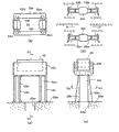
图6示出本发明的贮存箱的实施方式的第二例,(a)是与图3(a)同样的剖视图,(b)是沿着(a)的VIB-VIB线的剖视图。 6 shows a second example of an embodiment of the storage tank of the present invention, (a) is a cross-sectional view similar to FIG. 3( a ), and (b) is a cross-sectional view along line VIB-VIB of (a).
图7示出本发明的贮存箱的实施方式的第三例,(a)是与图3(a)同样的剖视图,(b)是沿着(a)的VIIB-VIIB线的剖视图。 7 shows a third example of an embodiment of the storage tank of the present invention, (a) is a cross-sectional view similar to FIG. 3( a ), and (b) is a cross-sectional view along line VIIB-VIIB of (a).
具体实施方式 Detailed ways
下面,使用附图说明用于实施本发明的方式。 Hereinafter, modes for implementing the present invention will be described using the drawings.
图1是示意包括本发明所涉及的贮存箱的实施方式的第一例的制动装置的图。 FIG. 1 is a diagram schematically showing a braking device including a first example of an embodiment of a storage tank according to the present invention.
如图1所示,该第一例的液压制动装置1基本上与以往已知的一般的2系统的液压制动装置相同。即,液压制动装置1包括制动踏板2、增力装置3、串联式主缸4、贮存箱5、以及制动缸6。
As shown in FIG. 1 , the hydraulic brake device 1 of the first example is basically the same as a conventionally known general two-system hydraulic brake device. That is, the hydraulic brake device 1 includes a
而且,若驾驶者踩下制动踏板2,则增力装置3工作,以预定的伺服比将踏板踏力增大输出。利用该增力装置3的输出,串联式主缸4的主活塞4a工作,将主工作液室4b的工作液供给一个系统的制动缸6,并且副活塞4c工作,将副工作液室4d的工作液供给另一个系统的制动缸6。若各制动系统的损失冲程消失,则串联式主缸4产生液压。该串联式主缸4的液压传递至各制动缸6,各制动缸6产生制动力,对各车轮7施加制动。
Then, when the driver depresses the
图2(a)是示出局部地切开该第一例的贮存箱的图,图2(b)是该第一例的贮存箱的长边方向的纵向剖视图。此外,在以下的说明中,各部位的底的高度的高低是指贮存箱安装在车身上且车辆置于水平状态下的高低。 FIG. 2( a ) is a partially cutaway view of the storage box of the first example, and FIG. 2( b ) is a longitudinal sectional view of the storage box of the first example in the longitudinal direction. In addition, in the following description, the height of the bottom of each part refers to the height when the storage tank is mounted on the vehicle body and the vehicle is placed in a horizontal state.
如图2(a)及(b)所示,用于该第一例的制动装置1的贮存箱5具有:储存向串联式主缸4供给的工作液且在上方开口的容器状的下半体8、封闭该下半体8的上端开口部的上半体9。在上半体9设有工作液注入口10,该工作液注入口10被帽11(图1中示出)开关。
As shown in FIGS. 2( a ) and ( b ), the
该第一例的下半体8具有工作液供给部12、工作液储存室13、设在这些工作液供给部12与工作液储存室13之间的工作液通路14。下半体8的上表面与上半体9的下表面被热熔接,下半体8的上端开口部被封闭。所以,工作液通过上半体9的工作液注入口10供给至工作液供给部12。
The
工作液储存室13具有液量检测室15、主工作液储存室16、副工作液储存室17。而且,在贮存箱5经由串联式主缸4安装在车身的状态下,从车辆前方(图2(b)中左方)向车辆后方(图2(b)中右方)依次配设工作液注入口10、工作液供给部12、液量检测室15、副工作液储存室17以及主工作液储存室16。
The working fluid storage chamber 13 has a liquid
工作液供给部12经由工作液通路14与液量检测室15始终连通。另外,液量检测室15与副工作液储存室17始终连通。进一步地,工作液供给部12经由工作液通路14的其他路径与主工作液储存室16始终连通。主工作液储存室16与副工作液储存室17被隔壁18隔开,但在隔壁18的上端18a的上方始终相互连通。主工作液储存室16内的工作液通过主工作液供给口16a供给至主缸4的主工作液室4b,并且副工作液储存室17内的工作液通过副工作液供给口17a供给至主缸4的副工作液室4d。
The hydraulic
在与液量检测室15对应的位置设有液量检测部19。该液量检测部19设在下半体8的前后方向(车辆前后方向)的大致中心,对储存在贮存箱5内的工作液的液量进行检测。如图3(a)放大所示,液量检测部19包括:配设在由圆筒状隔壁20包围的浮子室21内且在上端部具有磁体22的浮子23、在液量检测部19的上方部设在上半体9的外侧并利用磁体22而工作的行程开关24、圆柱状(圆棒状)的引导件25、梯形的引导件26、底面侧防吸附突起27。
A liquid
浮子室21利用形成于圆筒状隔壁20的直径比较小的连通孔20a,与圆筒状隔壁20的外周侧的液量检测室15始终连通。所以,若工作液储存在贮存箱5内直到液面位于连通孔20a的上方,则该工作液会通过连通孔20a而浸入浮子室21内。在这种情况下,浮子室21内的工作液的液面的高度与液量检测室15内的工作液的液面的高度始终相同。另外,即使例如由于车辆的急制动或急转弯等使圆筒状隔壁20的外部的贮存箱5内的工作液急剧移动,利用连通孔20a的节流作用,也能抑制浮子室21内的工作液的液面变动。据此,防止行程开关24的误动作。
The
图4示出该第一例的浮子及磁体,(a)是主视图,(b)是仰视图,(c)是俯视图,(d)是沿着(a)的IVD-IVD线的剖视图,(e)是沿着(d)的IVE-IVE线的剖视图。 Fig. 4 shows the float and the magnet of the first example, (a) is a front view, (b) is a bottom view, (c) is a top view, (d) is a sectional view along the IVD-IVD line of (a), (e) is a sectional view along the IVE-IVE line of (d).
如图4(a)至(e)所示,浮子23具有:浮子主体23a、在该浮子主体23a的上端朝向上方突出设置的侧视矩形且横截面矩形或者横截面圆形的一对磁体支柱23b、23c、设在这些磁体支柱23b、23c的上端的矩形容器状的磁体支撑部23d。
As shown in Fig. 4 (a) to (e), the
浮子主体23a具有:上下一对大直径圆形外周部23a1、23a2、在这些大直径圆形外周部23a1、23a2之间与其同心而设的小直径圆形外周部23a3。在大直径圆形外周部23a1、23a2和小直径圆形外周部23a3的中心,穿设有在上下方向贯穿的横截面圆形的引导孔23a4。
The
如图3(a)及(c)所示,一对定位肋32、33在圆筒状隔壁20的内周面上、在浮子室21从底面向上方延伸预定长度且与浮子室21的径向相对置而延伸设置。另一方面,如图3(a)、图4(a)、(b)及(d)所示,在浮子23的大直径圆形外周部23a1的外周缘部,在这些定位肋32、33上分别设有可嵌合的定位长槽34、35。所以,当浮子23容纳在浮子室21内时,通过各定位长槽34、35嵌合在定位肋32、33上,浮子23在周向被定位。据此,磁体22相对于行程开关24在周向被定位。特别是,在使用了磁体具有方向性的各向异性的磁体的情况下,由于能够将磁体相对于行程开关24在周向进行定位,因此能够更可靠地利用磁体来进行行程开关24的接通断开工作。所述定位肋32、33的预定长度被设定为当浮子23到达最下端位置时,上侧的大直径圆形外周部23a2不会进行干扰的长度。
As shown in Figure 3 (a) and (c), a pair of positioning
如图5(a)、(b)及(d)所示,磁体支柱23b、23c互相隔开预定的间隔而配置。据此,磁体支柱23b、23c的工作液的受压面积减小,即使如上所述贮存箱5内的工作液急剧移动,也能抑制由于移动的工作液而施加在磁体支柱23b、23c的力。所以,减小了因工作液的急剧的移动对浮子23的影响,防止行程开关24的误动作。
As shown in FIGS. 5( a ), ( b ) and ( d ), the
另外,如图5(a)至(d)所示,在各磁体支柱23b、23c上,分别在其两侧设有上部的宽度较小且下部的宽度较大的近似直角三角形板状的增强肋23b1、23b2;23c1、23c2(相当于本发明的支柱增强部件)。在这种情况下,这些增强肋23b1、23b2;23c1、23c2在金属模的滑动方向及铅垂方向延伸设置。各增强肋23b1、23b2;23c1、23c2分别对磁体支柱23b、23c进行增强。据此,抑制各磁体支柱23b、23c的弯曲。这些浮子主体23a、磁体支柱23b、23c、增强肋23b1、23b2;23c1、23c2以及磁体支撑部23d由发泡树脂一体模制成形。在这种情况下,如图5(d)所示,各增强肋23b1、23b2;23c1、23c2分别具有角度θ的取出斜面,使其厚度向前端减小。该取出斜面是金属模脱模时金属模进行滑动之际,浮子23不会成形收缩的斜面。所以,设有各增强肋23b1、23b2;23c1、23c2,也能抑制浮子23成形收缩。进一步地,各增强肋23b1、23b2;23c1、23c2的取出斜面形成于当填充树脂时不阻碍所述树脂的流动的方向上。据此,在浮子23的成型时,作为材料的树脂的填充性提高。
In addition, as shown in Figure 5(a) to (d), on each
在磁体支撑部23d上,磁体22与浮子23利用一体模制成形而被固定支撑。
The
如图2(a)、(b)及图3(a)所示,角筒状的行程开关安装部28与上半体9一体地设在上半体9的外表面。行程开关24从图2(a)的附图的跟前向与该附图垂直的方向(车辆左右方向)(图3(a)中为从右方向左方)插入安装到该行程开关安装部28中。行程开关24构成为以自力进行关闭的常闭开关。如图3(d)的实线及双点划线所示,通过浮子23根据浮子室21内的工作液的液面的高度在浮子室21内上下移动,磁体22也会上下移动。
As shown in FIGS. 2( a ), ( b ) and FIG. 3 ( a ), the angular cylinder-shaped travel
在工作液的液面的高度位于比预先规定的最小限的MIN位置稍高位置的情况下,浮子室21内的工作液的液面也为与该贮存箱5内的液面的高度位置相同高度的位置。因此,浮子23也处于与该液面的高度对应的高度位置。此时的浮子室21内的液面为行程开关24的接通断开切换液面(即警告灯的熄灯液面),警告灯不点亮。
When the height of the liquid level of the working fluid is located slightly higher than the predetermined minimum MIN position, the liquid level of the working fluid in the
另外,若制动缸6内消耗的制动液增加,贮存箱5内的工作液减少,浮子室21内的工作液的液面变低,则浮子23与磁体22一起与此对应地向下移动,磁体22离开行程开关24。直到浮子室21内的工作液的液面的高度为熄灯液面时,即使磁体22向下移动,行程开关24由于磁体22的磁力而维持断开状态,警告灯点亮。
In addition, if the brake fluid consumed in the
圆柱状(圆棒状)的引导件25在下半体8上,在浮子室21内位于圆筒状隔壁20的中心,从浮子室21的底面向上方且与下半体8一体突出地设置。在该引导件25中贯穿有浮子23的引导孔23a4。所以,浮子23被引导件25及圆筒状隔壁20的内周面引导而上下移动。在这种情况下,虽然在上端部设有磁体22的浮子23的重心位置位于上方,但即使像这样重心位置位于上方,但由于引导件25及圆筒状隔壁20的内周面(特别是引导件25),浮子23及磁体22几乎不会因其自重而倾斜,能够顺畅地上下移动。
A cylindrical (rod-shaped) guide 25 is located on the
进一步,如图3(a)所示,在引导件25的上端形成凸部36。该凸部36是下半体8的树脂成形时的排气用凸部。利用该凸部36,在下半体8的树脂成形时,有效地排出气体,因此使树脂良好地向引导件25的周围转移,引导件25的外周面被加工为光滑、整齐的面。在这种情况下,如图3(d)所示,也可以在引导件25的上端设有与该凸部36具有相同功能的凹部37,以代替凸部36(为便于说明,图3(d)中示出凹部37,以代替凸部36)。
Further, as shown in FIG. 3( a ), a
如图3(a)、(b)及(d)所示,梯形的引导件26分别与矩形的磁体支撑部23d的4边对应地设有4个。这些梯形的引导件26都由薄板形成为相同的梯形。在这种情况下,引导件26的上边的长度设定为比下边的长度长,并且,各引导件26的上边侧与上半体9一体成形。即,各引导件26从贮存箱5的上端内表面(顶板内表面)垂下。各引导件26分别具有倾斜的引导面26a。各引导件26中,互相对置的一对引导件26的引导面26a配置为随着朝向上方而互相接近。互相对置的一对引导件26的引导面26a间的中心设定为与引导件25的中心轴一致。
As shown in FIGS. 3( a ), ( b ) and ( d ), four
而且,如图3(d)的双点划线所示,若浮子23上升,则磁体支撑部23d的上端角部23d1、23d2与引导面26a抵接,被这些引导面26a引导。此外,在图3(d)中仅示出了磁体支撑部23d的长边侧的上端角部23d2,但对于磁体支撑部23d的短边侧的上端角部23d1也如此。据此,磁体22的中心相对于行程开关24的中心的位置被限制而居中。在这种情况下,若浮子23向上移动,则引导件25对浮子23的引导量减少,浮子23容易变得不稳定,但通过这样磁体支撑部23d由引导件26来引导,浮子23能稳定地向上移动。
3(d), when the
如图3(a)、(c)及(d)所示,底面侧防吸附突起27形成为半球状,在下半体8的浮子室21的底面与浮子23的下表面对置地设有预定个数(图示例中有4个)。在这种情况下,各底面侧防吸附突起27沿着以引导件25的中心轴为中心的同心圆,在圆周方向隔开等间隔而突出设置。而且,各底面侧防吸附突起27通过浮子主体23a的下表面与其抵接,在浮子主体23a的下表面与浮子室21的底面之间形成预定的间隙。据此,在浮子23向下移动至最大时,防止浮子主体23a的下表面紧密地吸附在浮子室21的底面。所以,在向贮存箱5内供给工作液时,工作液的液面上升并且浮子23容易向上移动,提高浮子23的浮起可靠性(工作可靠性)。
As shown in Figure 3 (a), (c) and (d), the bottom surface
根据该第一例的贮存箱5,将常闭开关即行程开关24配设在磁体22的上方,并且将该磁体22利用磁体支柱23b、23c设在浮子23的上端,进一步地,边用圆柱状(圆棒状)的引导件25来引导浮子23边使其上下移动。这样,通过利用磁体支柱23b、23c将磁体22支撑在浮子23的上端,能够增大浮子23的上下方向尺寸。所以,能够使浮子23根据工作液的液面顺畅且可靠地上下移动。此时,虽然在上端部设有磁体22的浮子23的重心位置位于上方,但即使这样重心位置位于上方,浮子23及磁体22也几乎不会因其自重而倾斜,能够使其顺畅地上下移动。据此,提高浮子23的工作性。
According to the
特别是,在各磁体支柱23b、23c上分别设有增强肋23b1、23b2;23c1、23c2。通过利用这些增强肋23b1、23b2;23c1、23c2来分别增强磁体支柱23b、23c,磁体支柱23b、23c的强度增大。所以,即使各磁体支柱23b、23c在例如包含磁体22的浮子23的搬送中等浮子23彼此之间碰撞,或受到以邻近的磁体22的磁力彼此之间的引力或斥力等为代表的外力,也能够抑制各磁体支柱23b、23c的弯曲。所以,能够进一步有效提高浮子23的工作性。据此,能够使磁体以稳定的姿势进行上下移动,能够使行程开关稳定工作。
In particular, reinforcing
另外,各增强肋23b1、23b2;23c1、23c2分别具有角度θ的取出斜面,使其厚度向前端减小。据此,在金属模脱模时金属模滑动之际,能够抑制各磁体支柱23b、23c的变形弯曲,并且即使设有各增强肋23b1、23b2;23c1、23c2,也能够抑制浮子23成形收缩。所以,由于抑制了浮子23的变形,因此,能够进一步有效提高浮子23的工作性。而且,由于各增强肋23b1、23b2;23c1、23c2具有如上所述的取出斜面,因此能够减小各增强肋23b1、23b2;23c1、23c2对于贮存箱5内的工作液在车辆前后方向的移动的阻力。据此,即使工作液在车辆前后方向移动,也能使浮子主体23a的姿势稳定,能够抑制液面下降时(工作液减少时)的行程开关24的误动作。进一步,通过将各增强肋23b1、23b2;23c1、23c2的取出斜面形成于填充树脂时不阻碍材料即树脂的流动的方向上,能够提高树脂的填充性,能够降低树脂的填充不足或者树脂的填充不良。
In addition, each of the reinforcing
进一步地,由于用磁体支柱23b、23c构成浮子23的上方部,因此可以减小磁体支柱23b、23c的工作液的受压面积。据此,即使例如由于车辆的急制动或急转弯等使贮存箱5内的工作液急剧移动,也能够抑制由于移动的工作液而施加在磁体支柱23b、23c的力。所以,能够减小因工作液的急剧的移动对浮子23的影响,能够进一步有效防止行程开关24的误动作,能够更可靠地防止警告灯的误点亮。
Furthermore, since the upper part of the
进一步地,通过对磁体支柱23b、23c的长度、直径进行各种变更,能够对浮子室21内的体积进行各种变更。所以,对于根据装载贮存箱5的车辆的车种而各不相同的贮存箱5,能够更灵活且可靠地进行对应。
Furthermore, by variously changing the length and diameter of the
而且,由于将对置的引导件26的引导面26a的距离向上方而减小的梯形的引导件26与上半体9一体而设,因此能够使磁体支撑部23d的上端角部23d1、23d2被倾斜的引导面26a引导,使磁体22向上移动。在这种情况下,由于被引导件25引导并向上移动预定量的浮子23被该引导件26引导,因此,即使浮子23因引导件25的引导量减少,也能用引导件26可靠地引导浮子23,使磁体22相对于行程开关24的位置被限制而居中。据此,即使浮子23的重心位置位于上方,也能够更可靠地抑制浮子23及磁体22的倾斜移动。所以,能够更可靠地使浮子23及磁体22因其自重进行行程开关24的接通断开工作。
Moreover, since the
另外,由于将磁体22设在浮子23的上端,因此能够使磁体22接近行程开关24。据此,能够使熄灯液面远离行程开关24。所以,能够将贮存箱5的工作液的储存容量设定得更大。而且,即使将熄灯液面远离行程开关24,浮子23在熄灯液面时的磁体22的位置也能够进一步接近行程开关24。据此,能够提高行程开关24的工作可靠性。其结果是,能够减小磁体的磁力,能够降低成本。
In addition, since the
进一步地,由于使引导件25从浮子室21的底面向上方突出设置,并且用梯形的薄板形成从上半体9的内表面垂下的引导件26,因此即使设有这些引导件25、26,也能够抑制产生空气积存。
Further, since the
进一步地,通过用引导件25来引导浮子23,在浮子23的上下移动时,能够使滑动阻力作用在浮子23上。据此,能够使行程开关24的接通断开工作产生滞后。所以,能够防止行程开关24的误动作,能够防止警告灯的误点亮。此外,该滑动阻力被设定为不会给浮子23的上下移动的可靠性带来影响程度的大小。
Furthermore, by guiding the
进一步地,由于利用连通孔20a使圆筒状隔壁20内的浮子室21与圆筒状隔壁20外的液量检测室15始终连通,因此即使例如由于车辆的急制动或急转弯等使圆筒状隔壁20的外部的贮存箱5内的工作液急剧移动,利用连通孔20a的节流作用,也能够抑制浮子室21内的工作液的液面变动。据此,能够防止行程开关24的误动作,能够防止警告灯的误点亮。
Furthermore, since the
图6示出本发明的贮存箱的实施方式的第二例,(a)是与图3(a)同样的剖视图,(b)是沿着(a)的VIB-VIB线的剖视图。此外,在以后的各例的说明中,通过在与该例之前记载的例子相同的构成要素标注相同的附图标记,其详细的说明省略。 6 shows a second example of an embodiment of the storage tank of the present invention, (a) is a cross-sectional view similar to FIG. 3( a ), and (b) is a cross-sectional view along line VIB-VIB of (a). In addition, in the description of each of the following examples, the same reference numerals are attached to the same constituent elements as those of the examples described before this example, and the detailed description thereof will be omitted.
在所述第一例中,各磁体支柱23b、23c形成为侧视矩形且横截面矩形或者横截面圆形,但如图6(a)及(b)所示,在该第二例的贮存箱5中,各磁体支柱23b、23c形成为侧视梯形且横截面矩形。这样,通过各磁体支柱23b、23c形成为侧视梯形,与所述第一例相比,增大了各磁体支柱23b、23c的强度。即,第二例的各磁体支柱23b、23c为高强度构造。
In the first example, each
另外,浮子主体23a相对于熄灯液面的高度位置的相对高度位置,与浮子主体23a相对于前述图3(a)所示的第一例的熄灯液面的高度位置的相对高度位置不同。即,在第一例中浮子主体23a的上表面位于熄灯液面的高度位置的略上方,但在该第二例的贮存箱5中,浮子主体23a的上表面23a5位于熄灯液面的高度位置的下方。此时,熄灯液面相对于第一例的磁体22的高度位置的相对高度位置与熄灯液面相对于第二例的磁体22的高度位置的相对高度位置相同。所以,在该第二例的贮存箱5中,各磁体支柱23b、23c的高度比第一例的各磁体支柱23b、23c的高度更高。
In addition, the relative height position of the
此外,在该第二例的贮存箱5中,在上方的大直径圆形外周部23a2的外周,狭缝状的预定个数(在图示例中为2个)的工作液通路38、39在上下方向延伸设置。各工作液通路38、39在圆周方向隔开等间隔而设。利用这些工作液通路38、39,工作液从浮子23的上方向下方良好地流动,提高浮子23的浮起可靠性。
In addition, in the
根据该第二例的贮存箱5,由于各磁体支柱23b、23c为高强度构造,因此即使不设有所述第一例的增强肋23b1、23b2;23c1、23c2,也能够抑制各磁体支柱23b、23c的弯曲变形。
According to the
此外,在该第二例中,未设有第一例的定位肋32、33及定位长槽34、35,但在第二例中也可以设有第一例的定位肋32、33及定位长槽34、35。另外,工作液通路38、39在第二例中可以同样地设置。
In addition, in this second example, the
该第二例的贮存箱5的其他结构及其他作用效果与所述第一例相同。
Other structures and other functions and effects of the
图7示出本发明的贮存箱的实施方式的第三例,(a)是与图3(a)同样的剖视图,(b)是沿着(a)的VIIB-VIIB线的剖视图。 7 shows a third example of an embodiment of the storage tank of the present invention, (a) is a cross-sectional view similar to FIG. 3( a ), and (b) is a cross-sectional view along line VIIB-VIIB of (a).
如图7(a)及(b)所示,在该第三例的贮存箱3中,熄灯液面相对于磁体22的高度位置的相对高度位置与熄灯液面相对于第一例的磁体22的高度位置的相对高度位置不同。即,熄灯液面相对于第三例的磁体22的高度位置的相对高度位置与第一例的相比较小。此时,浮子主体23a的上表面23a5相对于第三例的熄灯液面的高度位置的上方突出量与第一例的该上方突出量相同。所以,在该第三例的贮存箱5中,各磁体支柱23b、23c的高度比第一例的各磁体支柱23b、23c的高度低。这样,通过各磁体支柱23b、23c较低,与所述第一例相比,增大了各磁体支柱23b、23c的强度。即,第三例的各磁体支柱23b、23c为高强度构造。
As shown in Figure 7 (a) and (b), in the
根据该第三例的贮存箱5,由于各磁体支柱23b、23c为高强度构造,因此即使不设有所述第一例的增强肋23b1、23b2;23c1、23c2,也能够抑制各磁体支柱23b、23c的弯曲变形。
According to the
该第三例的贮存箱5的其他结构及其他作用效果与所述第二例相同。
Other structures and other functions and effects of the
此外,本发明不限于上述例,在权利要求书所记载的事项的范围内可以进行各种设计变更。 In addition, this invention is not limited to the said example, Various design changes are possible within the scope of the matter described in a claim.
本发明所涉及的贮存箱能够适用于利用了油压等液压的液压制动装置、液压离合装置所使用的储存工作液的贮存箱。 The storage tank according to the present invention can be applied to a storage tank for storing working fluid used in a hydraulic brake device and a hydraulic clutch device using hydraulic pressure such as oil pressure.
另外,本发明所涉及的制动装置能够适用于使用储存在贮存箱的工作液来对车轮制动的制动装置。 In addition, the brake device according to the present invention can be applied to a brake device that brakes wheels using the hydraulic fluid stored in the storage tank.
Claims (5)
Applications Claiming Priority (3)
| Application Number | Priority Date | Filing Date | Title |
|---|---|---|---|
| JP2010-014178 | 2010-01-26 | ||
| JP2010014178 | 2010-01-26 | ||
| PCT/JP2011/000319 WO2011093044A1 (en) | 2010-01-26 | 2011-01-21 | Reservoir tank and brake device employing same |
Publications (2)
| Publication Number | Publication Date |
|---|---|
| CN102712310A true CN102712310A (en) | 2012-10-03 |
| CN102712310B CN102712310B (en) | 2015-01-07 |
Family
ID=44319043
Family Applications (1)
| Application Number | Title | Priority Date | Filing Date |
|---|---|---|---|
| CN201180007301.1A Expired - Fee Related CN102712310B (en) | 2010-01-26 | 2011-01-21 | Reservoir tank and brake device employing same |
Country Status (5)
| Country | Link |
|---|---|
| US (1) | US20120292982A1 (en) |
| EP (1) | EP2529988B1 (en) |
| JP (1) | JP5497073B2 (en) |
| CN (1) | CN102712310B (en) |
| WO (1) | WO2011093044A1 (en) |
Families Citing this family (4)
| Publication number | Priority date | Publication date | Assignee | Title |
|---|---|---|---|---|
| FR3001935B1 (en) * | 2013-02-08 | 2015-03-20 | Illinois Tool Works | LIQUID TANK FOR VEHICLE AND AUTOMOTIVE SYSTEM COMPRISING SUCH A TANK |
| US11951961B2 (en) * | 2019-08-19 | 2024-04-09 | ZF Active Safety US Inc. | Method for the functional testing of a fluid level warning indicator |
| JP2021094976A (en) * | 2019-12-17 | 2021-06-24 | ボッシュ株式会社 | Reservoir tank |
| JP7806622B2 (en) * | 2022-06-16 | 2026-01-27 | 株式会社アドヴィックス | Reservoir tank and brake fluid pressure generating device |
Citations (6)
| Publication number | Priority date | Publication date | Assignee | Title |
|---|---|---|---|---|
| US3167623A (en) * | 1962-08-15 | 1965-01-26 | Kaleta Theodore | Liquid level switch with normally closed contacts and auxiliary means to maintain contacts in engaged position |
| JPS58108953U (en) * | 1982-01-21 | 1983-07-25 | 株式会社ナブコ | Hydraulic fluid reservoir |
| JPS6130573U (en) * | 1984-07-30 | 1986-02-24 | リズム自動車部品製造株式会社 | Reservoir tank for master cylinder |
| JPS6215081Y2 (en) * | 1981-09-18 | 1987-04-17 | ||
| US20020011750A1 (en) * | 2000-06-26 | 2002-01-31 | Sumitomo (Sei) Brake Systems, Inc. | Brake system for electric motor-powered vehicle |
| CN1938805A (en) * | 2004-03-26 | 2007-03-28 | 大陆-特韦斯捷克有限责任公司 | Device for monitoring the level of a container |
Family Cites Families (8)
| Publication number | Priority date | Publication date | Assignee | Title |
|---|---|---|---|---|
| US3293579A (en) * | 1965-04-23 | 1966-12-20 | Acme Machine Works Inc | Liquid level indicator incorporating permanent magnets |
| JPS50110664U (en) * | 1974-02-19 | 1975-09-09 | ||
| JPS6125263U (en) * | 1984-07-05 | 1986-02-14 | 株式会社ナブコ | Reservoir with liquid level detector |
| JPS64674Y2 (en) * | 1984-09-27 | 1989-01-09 | ||
| JPS61146662A (en) * | 1984-12-19 | 1986-07-04 | Nippon Air Brake Co Ltd | Master cylinder |
| JPS62193526U (en) * | 1986-05-29 | 1987-12-09 | ||
| JPS63115016A (en) * | 1986-10-31 | 1988-05-19 | Toyoda Gosei Co Ltd | Liquid level sensor |
| DE10310170A1 (en) * | 2003-03-08 | 2004-09-16 | Wiesauplast Kunststoff Und Formenbau Gmbh & Co. Kg | Pressure fluid supply tank |
-
2011
- 2011-01-21 JP JP2011551751A patent/JP5497073B2/en not_active Expired - Fee Related
- 2011-01-21 EP EP11736761.5A patent/EP2529988B1/en not_active Not-in-force
- 2011-01-21 US US13/522,369 patent/US20120292982A1/en not_active Abandoned
- 2011-01-21 WO PCT/JP2011/000319 patent/WO2011093044A1/en not_active Ceased
- 2011-01-21 CN CN201180007301.1A patent/CN102712310B/en not_active Expired - Fee Related
Patent Citations (6)
| Publication number | Priority date | Publication date | Assignee | Title |
|---|---|---|---|---|
| US3167623A (en) * | 1962-08-15 | 1965-01-26 | Kaleta Theodore | Liquid level switch with normally closed contacts and auxiliary means to maintain contacts in engaged position |
| JPS6215081Y2 (en) * | 1981-09-18 | 1987-04-17 | ||
| JPS58108953U (en) * | 1982-01-21 | 1983-07-25 | 株式会社ナブコ | Hydraulic fluid reservoir |
| JPS6130573U (en) * | 1984-07-30 | 1986-02-24 | リズム自動車部品製造株式会社 | Reservoir tank for master cylinder |
| US20020011750A1 (en) * | 2000-06-26 | 2002-01-31 | Sumitomo (Sei) Brake Systems, Inc. | Brake system for electric motor-powered vehicle |
| CN1938805A (en) * | 2004-03-26 | 2007-03-28 | 大陆-特韦斯捷克有限责任公司 | Device for monitoring the level of a container |
Also Published As
| Publication number | Publication date |
|---|---|
| WO2011093044A1 (en) | 2011-08-04 |
| JPWO2011093044A1 (en) | 2013-05-30 |
| EP2529988B1 (en) | 2017-03-15 |
| EP2529988A1 (en) | 2012-12-05 |
| EP2529988A4 (en) | 2015-08-19 |
| CN102712310B (en) | 2015-01-07 |
| JP5497073B2 (en) | 2014-05-21 |
| US20120292982A1 (en) | 2012-11-22 |
Similar Documents
| Publication | Publication Date | Title |
|---|---|---|
| CN102712310B (en) | Reservoir tank and brake device employing same | |
| CN101289085A (en) | Oil reservoir and master cylinder | |
| US10759406B2 (en) | Reservoir tank and vehicle brake apparatus | |
| EP2228272B1 (en) | Reservoir tank and brake device using the reservoir tank | |
| JP5199191B2 (en) | Reservoir tank and brake device using the same | |
| KR20230000233A (en) | Brake Oil Reservoir for Vehicles | |
| JP2002029408A (en) | Reservoir for hydraulic master cylinder for vehicles | |
| WO2010035907A1 (en) | Reservoir and brake device using same | |
| JP5220719B2 (en) | Reservoir for vehicle hydraulic master cylinder | |
| JP5334723B2 (en) | Reservoir tank and brake device using the same | |
| JP2010064680A (en) | Reservoir tank and brake device using the same | |
| JP6172747B2 (en) | Reservoir tank and brake system using the same | |
| JP6487696B2 (en) | Reservoir for vehicle hydraulic master cylinder | |
| JP5207552B2 (en) | Reservoir tank and brake device using the same | |
| KR20230156505A (en) | Reservoir tank for brake system | |
| JP5207534B2 (en) | Reservoir tank and brake device using the same | |
| JP2017047713A (en) | Reservoir tank of hydraulic fluid of vehicle hydraulic device, vehicle hydraulic brake device, and manufacturing method of reservoir tank of hydraulic fluid of vehicle hydraulic device | |
| JP2007205749A (en) | Liquid level detection device and liquid storage container | |
| JP3540135B2 (en) | Hydraulic fluid reservoir for vehicles | |
| JP2011126322A (en) | Reservoir tank and hydraulic operation device with the same | |
| JP2010076724A (en) | Reservoir tank and brake device using the same | |
| JP2002206960A (en) | Liquid level detector | |
| JP2011143736A (en) | Reservoir tank and brake device using the same | |
| JP2010069977A (en) | Reservoir tank and brake device using the same | |
| JPH1029528A (en) | Liquid reservoir device |
Legal Events
| Date | Code | Title | Description |
|---|---|---|---|
| C06 | Publication | ||
| PB01 | Publication | ||
| C10 | Entry into substantive examination | ||
| SE01 | Entry into force of request for substantive examination | ||
| C14 | Grant of patent or utility model | ||
| GR01 | Patent grant | ||
| CF01 | Termination of patent right due to non-payment of annual fee |
Granted publication date: 20150107 Termination date: 20200121 |
|
| CF01 | Termination of patent right due to non-payment of annual fee |