CN102713552A - Moment calibrating apparatus for multi-component force gauge and method of moment calibration - Google Patents
Moment calibrating apparatus for multi-component force gauge and method of moment calibration Download PDFInfo
- Publication number
- CN102713552A CN102713552A CN2011800074194A CN201180007419A CN102713552A CN 102713552 A CN102713552 A CN 102713552A CN 2011800074194 A CN2011800074194 A CN 2011800074194A CN 201180007419 A CN201180007419 A CN 201180007419A CN 102713552 A CN102713552 A CN 102713552A
- Authority
- CN
- China
- Prior art keywords
- mentioned
- torsion
- load
- moment
- component meter
- Prior art date
- Legal status (The legal status is an assumption and is not a legal conclusion. Google has not performed a legal analysis and makes no representation as to the accuracy of the status listed.)
- Granted
Links
Images


Classifications
-
- G—PHYSICS
- G01—MEASURING; TESTING
- G01L—MEASURING FORCE, STRESS, TORQUE, WORK, MECHANICAL POWER, MECHANICAL EFFICIENCY, OR FLUID PRESSURE
- G01L25/00—Testing or calibrating of apparatus for measuring force, torque, work, mechanical power, or mechanical efficiency
-
- G—PHYSICS
- G01—MEASURING; TESTING
- G01L—MEASURING FORCE, STRESS, TORQUE, WORK, MECHANICAL POWER, MECHANICAL EFFICIENCY, OR FLUID PRESSURE
- G01L25/00—Testing or calibrating of apparatus for measuring force, torque, work, mechanical power, or mechanical efficiency
- G01L25/003—Testing or calibrating of apparatus for measuring force, torque, work, mechanical power, or mechanical efficiency for measuring torque
-
- G—PHYSICS
- G01—MEASURING; TESTING
- G01M—TESTING STATIC OR DYNAMIC BALANCE OF MACHINES OR STRUCTURES; TESTING OF STRUCTURES OR APPARATUS, NOT OTHERWISE PROVIDED FOR
- G01M1/00—Testing static or dynamic balance of machines or structures
- G01M1/02—Details of balancing machines or devices
- G01M1/04—Adaptation of bearing support assemblies for receiving the body to be tested
- G01M1/045—Adaptation of bearing support assemblies for receiving the body to be tested the body being a vehicle wheel
Landscapes
- Physics & Mathematics (AREA)
- General Physics & Mathematics (AREA)
- Force Measurement Appropriate To Specific Purposes (AREA)
Abstract
A moment calibrating apparatus (1) is provided with an elongated force transmitting member (6) for transmitting a force applied to the end portion thereof to a multi-component force gauge (5), a load applying mechanism (7) for applying a load without changing the direction of the force along a direction perpendicular to said end portion, and a calculation unit (8) for calculating a true moment free from the effect of a perpendicular load on the basis of the moment value around the axis in the direction orthogonal to the perpendicular direction, measured by the multi-component force gauge (5) under the condition that said perpendicular load along the direction perpendicular to said end portion is applied by the load applying mechanism (7), wherein a moment calibration of the multi-component force gauge (5) is performed using said true moment calculated by the calculation unit (8).
Description
Technical field
The present invention relates to the torsion calibration device and the torque calibration method of many a kind of component meters.
Background technology
At the tyre testing apparatus that is used for special inspection, evaluation, exploitation etc.; Be provided with many component meter, its can measure put on the tire that joins with the road surface and rotate along vertical 3 power (Fx, Fy, Fz) and around these moment of torsion (Mx, My, Mz).This many component meter must be calibrated when being assembled into tyre testing apparatus for the first time.In addition, even if after being assembled into tyre testing apparatus, for the measuring accuracy of maintenance energy and moment of torsion also need for example whenever be calibrated many component meter at a distance from given time continually.
For example, a kind of method of many component meter self and anchor clamps of calibration usefulness etc. calibrated are disclosed in patent documentation 1.In this calibration steps, many component meter is installed counterweight via rope with belt wheel (pulley), the power that will be confirmed by counterweight and offer many component meter by the moment of torsion of counterweight generation is calibrated many component meter.This calibration steps is that the many component meter that takes off from tyre testing apparatus is monolithically carried out Calibration Method, is not to calibrate in that many component meter is assembled under the state in the tyre testing apparatus.
On the other hand, also have and many component meter is being built in the calibrating installation of calibrating under the state of tire mandrel.For example; Fig. 4 representes a kind of calibrating installation, and in tyre testing apparatus, said tyre testing apparatus is built-in many component meter in rotating the tire mandrel that has the main shaft that keeps tire freely; Wherein, under the state that many component meter is built in the tire mandrel, carry out the calibration of many component meter.This calibrating installation is to make the on-the-spot device that uses practically.
In this calibrating installation, the moment of torsion of many component meter is calibrated as follows.That is, in this calibrating installation, the force transmission member of strip extends along its direction of principal axis from the top of main shaft, on the top of this force transmission member rope is installed.Top at rope links via pulley counterweight is arranged, and applies power Fz upwards to the top of force transmission member.Thus, apply the long-pending moment of torsion Mx and the power Fz that makes progress of the length L of the load Fz that is equivalent to counterweight and force transmission member around the x betwixt mountains at the installed position of tire.In order correctly in many component meter, to detect moment of torsion, need under the state that does not have power Fz upwards, measure.Thereby, in order to eliminate this power Fz the installation site of tire is linked the counterweight of identical weight via rope, thereby apply power Fz downwards.
If constitute in this wise, then on many component meter, only apply moment of torsion Mx, can realize the calibration of the moment of torsion Mx of many component meter.
But; In the torque calibration method in the past of above-mentioned that kind; No matter be the calibrating installation monolithically many component meter calibrated, or the calibrating installation of under the state that many component meter is built in the tire mandrel, many component meter being calibrated, all must apply and be parallel to each other and reverse up and down load to force transmission member.Therefore, in these calibrating installations, as Fig. 4 institute is illustrative, need be used for pulling the pulley of rope to set direction (Fig. 4 is to the top).
But, if use pulley, then can produce friction force between pulley and the rope, because the precision of this friction force torque calibration can reduce.And when using pulley, the friction of the slipping plane of pulley (bearing) also can become the reason that precision reduces.In addition, in example shown in Figure 4, if the load that puts on force transmission member then can not correctly apply moment of torsion Mx to many component meter, so the installation site of pulley must be strictly involutory with the vertical top of force transmission member from the vertical direction dislocation.The position of such pulley is involutory to be meticulous and time-consuming operation, the operation property variation of torque calibration.
In addition, rope and wirerope are generally applied and reverse, reverse as the twisting resistance that rises thereby produce by this and act on force transmission member.This twisting resistance strengthens along with load sometimes and puts on many component meter as error.Thereby, in the torque calibration method of using rope and wirerope, there is the bigger hysteresis that causes by above-mentioned friction force and twisting resistance, so can not realize high-precision torque calibration owing to this hysteresis.
Patent documentation 1: japanese kokai publication sho 59-151032 communique.
Summary of the invention
The present invention is in view of the above problems and proposes, and its purpose is to provide a kind of torsion calibration device and calibration steps of many component meter of can high precision and efficiently moment of torsion being calibrated.
The torsion calibration device of many component meter of the present invention can be measured to comprise along the power of axle and become score value with at least two of moment of torsion of axle of winding perpendicular to this.This torsion calibration device has: rectangular force transmission member; Have the position of the base end side that links with above-mentioned many component meter and be positioned at the position with the tip side of the position opposition side of above-mentioned base end side, will pass to above-mentioned many component meter to the power of the position of above-mentioned tip side input; The load applying mechanism, to the position of the above-mentioned tip side of above-mentioned force transmission member along vertical direction and do not change the imposed load towards ground of power; Calculating part; Be based on from above-mentioned load applying mechanism the position of above-mentioned tip side is applied under the state of the vertical load of vertical direction by the torque value of winding of measuring of above-mentioned many component meter perpendicular to the axle of the direction of vertical direction; The real moment of torsion of above-mentioned vertical load influence has been got rid of in calculating, uses the above-mentioned real moment of torsion of in aforementioned calculation portion, calculating to carry out the torque calibration of above-mentioned many component meter.
Description of drawings
Fig. 1 is the front view of the torsion calibration device of first embodiment calibrated of the moment of torsion of expression opposing connection x axis of orientation.
Fig. 2 is the front view of the torsion calibration device of second embodiment calibrated of the moment of torsion of expression opposing connection x axis of orientation.
Fig. 3 is the front view of the torsion calibration device of second embodiment calibrated of the moment of torsion of expression opposing connection y axis of orientation.
Fig. 4 is the torsion calibration device front view in the past that counterweight is used in expression.
Embodiment
(first embodiment)
Below based on the torsion calibration device 1 and the calibration steps of description of drawings first embodiment of the present invention.
Before the formation of explanation torsion calibration device 1, at first explanation is equipped with the tyre testing apparatus 2 of torsion calibration device 1.
As shown in Figure 1, tyre testing apparatus 2 has: the axle center towards left and right directions the main shaft 3, the housing 4 that supports this main shaft 3 that set and the many component meter 5 that is arranged at housing 4.Between main shaft 3 and housing 4, be provided with bearing 26.Bearing 26 rotates main shaft 3 supportings freely with respect to housing 4 for the axle that winds towards left and right directions.Can use not shown wheel rim etc. on the top of main shaft 3 (left end) and tire T is installed.Through making main shaft 3, can make the tire T that is installed on main shaft 3 wind axle rotation towards left and right directions with respect to housing 4 rotations.In addition, housing 4 is supported on the framework of tyre testing apparatus.
As shown in Figure 1, the torsion calibration device 1 of first embodiment is the device that the power of being measured by many component meter of tyre testing apparatus 25 (load) and moment of torsion are calibrated.Torsion calibration device 1 has: force transmission member 6 passes to many component meter 5 with the power of importing; Load applying mechanism 7, along vertical direction to these force transmission member 6 imposed loads; With calculating part 8, calculate real moment of torsion, said real moment of torsion is the value after got rid of vertical load influence at the torque value that is measured by many component meter 5 under the state that has been applied in from the vertical load of this load applying mechanism 7.
This torsion calibration device 1 is according to which moment of torsion of Mx and Mz calibrating, and the formation that applies direction etc. of the installation of force transmission member 6 and load is different.Therefore, at first lift through the torsion calibration device 1 of first embodiment is described to force transmission member 6 imposed load Fz and to the situation that moment of torsion Mx calibrates as an example.
In addition, in the following explanation, with Fig. 1 up and down as explanation during torsion calibration device 1 about, left side and right side with the left side of Fig. 1 and right side during as explanation torsion calibration device 1.In addition, in the explanation of load and moment of torsion, the left and right directions of Fig. 1 is called the y direction, above-below direction is called the z direction, will be called the x direction with the vertical direction of both sides of y direction and z direction.
Be formed with recess 10 on the lower surface at the position of the tip side of force transmission member 6 towards ground, top depression.In this recess 10, embed and accept parts 11.This accepts the loading transfer portion that states after parts 11 constitute.Accept parts 11 below configuration to the load applying mechanism 7 of force transmission member 6 imposed loads.
7 pairs of force transmission members 6 of load applying mechanism are along the vertical direction imposed load.As load applying mechanism 7, can use the variety of way towards counterweight formula that does not change and fluid pressure type etc. of power in applying the path of power.In this embodiment, load applying mechanism 7 has the below that is disposed at force transmission member 6 and to the pressure cylinder 13 of these force transmission member 6 imposed loads with support the supporting station 14 of this pressure cylinder 13.
When moment of torsion is calibrated, need apply vertical load to force transmission member 6 a certain side along the vertical direction, make the moment of torsion that produces set value in the tire installation site.But the load that is applied by load applying mechanism 7 is that the generation moment of torsion is necessary, and is to be detected in many component meter 5 with moment of torsion, so be difficult to realize the high-precision calibration of moment of torsion.Therefore, as those skilled in the art's technological general knowledge, need apply the load that the load that is used to produce moment of torsion and applies is offset in addition for load applying mechanism 7.The load of this counteracting usefulness is opposite up and down with the action direction of the loading force that applies in order to produce moment of torsion.That is, force transmission member 6 is applied the load and the load of offsetting usefulness that the opposite up and down and moment of torsion that be parallel to each other of action direction produces usefulness.
But,, need be easy to generate by the rope that reverses the error that causes and be easy to generate pulley of the error that causes by friction etc. for the load applying mechanism that utilizes the counterweight formula applies the load of such vertical direction.In addition, force transmission member 6 is provided to above load the time, need the installation site of pulley is strictly involutory and make the action direction of load correctly involutory with vertical direction.But, if the load change that applies then the installation site of pulley must change, thus in the reality, with the installation site of pulley correctly involutory be difficult in vertical direction (in other words, the load that applies of order towards involutory) with vertical direction.
Therefore, in the torsion calibration device 1 of first embodiment, along the load applying mechanism 7 of vertical direction imposed load position with respect to the tip side of force transmission member 6, can be when not using pulley power towards changing.In addition, torsion calibration device 1 has calculating part 8, and it calculates the real moment of torsion after get rid of vertical load influence at the torque value that is measured by many component meter 5 under the state that has applied from the vertical load of this load applying mechanism 7.Thus, can use the real moment of torsion of in calculating part 8, calculating to carry out the torque calibration of many component meter 5.
Particularly, the load applying mechanism 7 of this embodiment has the below that is disposed at force transmission member 6 and to the pressure cylinder 13 of force transmission member 6 imposed loads with support this pressure cylinder 13 and pressure cylinder 13 is positioned the supporting station 14 of below slightly that load applies the position.The load that pressure cylinder 13 is configured to always to be positioned at force transmission member 6 applies the below of position P.
Supporting station 14 is by pin etc. and be located in motionless (for example, not having driven simulated roadway).14 pairs of pressure cylinders 13 of supporting station position and make that always set load being applied position P by pressure cylinder 13 applies the load that vertical direction makes progress from the below.This load applies position P and is set in the separation point position that separates certain distance L from the left end of main shaft 3 in the horizontal direction.In other words, load applies position P and is set in the position of leaving certain distance from many component meter 5.
Loading transfer portion has and is being arranged at the spheric seating 17 and the push strut 21 that concavity ground on the parts 11 forms of accepting of force transmission member 6 sides, and it has the protuberance that forms dome shape (spheric seating) that is arranged at pressure cylinder 13 sides.Accept parts 11 and apply the recess 10 that position P (be positioned at from the load of the position of the left end distance of separation L of main shaft 3 and apply position P) embeds the lower surface that is formed at force transmission member 6 being positioned at apart from load from the set distance of many component meter 5.The protuberance that is arranged at the upper end of push strut 21 forms spheric seating, and said spheric seating is made up of the sphere of the little radius-of-curvature of the spheric seating that has than accepts parts 11 17.Accept parts 11 and see that with the center of the radius-of-curvature of spheric seating 17 mode consistent with its rotation center is installed on recess 10 on the direction of principal axis of main shaft 3.Thus, the positioning operation of the sense of rotation of the main shaft 3 in the force transmission member 16 becomes simple.In addition, accept parts 11 and install in the following manner: when the direction of principal axis of pressure cylinder 13 is seen, on the sphere of spheric seating 17 to above the point of depression be positioned at load and apply position P.
Calculating part 8 is calculated the real moment of torsion after got rid of vertical load influence at the torque value that is measured by many component meter 5 under the state that applies vertical load from load applying mechanism 7.Load that input is measured by the load measurement device 16 of the top that is arranged at pressure cylinder 13 in calculating part 8 and load and the torque value that measures by many component meter 5.This calculating part 8 can be exported the real moment of torsion of calculating based on load and the torque value of input.Calculating part 8 can use computer etc. particularly.Processing shown in the torque calibration method that calculating part 8 is stated after can carrying out.
But; Above-mentioned example is that force transmission member 6 is up applied vertical load Fz and device that the moment of torsion Mx that results from the tire installation site is calibrated; But for around the moment of torsion My of y axis of orientation the time, the formation of device is different with above-mentioned formation at the moment of torsion of wanting to calibrate.
In above-mentioned torsion calibration device 1, can measure moment of torsion Mx respectively, Mz like this around the axle of x direction and z direction.
Then, the torque calibration method of using above-mentioned torsion calibration device 1 is described.The situation that moment of torsion Mx is calibrated if this torque calibration method is given an example then as follows.
In the calibration steps of moment of torsion Mx, at first, many component meter 5 (left end of main shaft 3) is installed rectangular force transmission member 6 base end side the position and can the power at the position of the tip side that inputs to force transmission member 6 be passed to many component meter 5.And, the position of the tip side of force transmission member 6 is applied load Fz upwards along vertical direction, calculate from having got rid of the real moment of torsion Mx of the influence of vertical load Fz applying the torque value of measuring by many component meter 5 under the state of this vertical load Fz.Then, use the real moment of torsion Mx that calculates to carry out the torque calibration of many component meter 5.This torque calibration method is done as follows particularly.
At first, use bolt 9 to firmly fix the base end side of force transmission member 6 in the left end of main shaft 3 of having taken off tire T and the wheel rim of this tire T being installed.Force transmission member 6 is installed towards the mode of horizontal direction along the y direction with its direction of principal axis.And, the position of the tip side that is arranged at force transmission member 6 accept parts 11 below set load applying mechanism 7.Load applying mechanism 7 is configured to, and the spheric seating of convex that is arranged at the top of push strut 21 applies closely being close to 17 of the spheric seatings of accepting parts 11 of position in load and contacts.
And, make pressure cylinder 13 elongation of load applying mechanism 7 and the position of the tip side of force transmission member 6 is applied load upwards along vertical direction.Thus, be arranged at pressure cylinder 13 above load measurement device 16 in, measure at least the load Fz of the vertical direction that the elongation owing to pressure cylinder 13 produces.The load Fz that measures is admitted to calculating part 8.
On the other hand, put in the load that makes progress on the force transmission member 6 at position of tip side, produce and make the moment of torsion Mx of force transmission member 6 with respect to the tire installation site around the axle rotation of x direction from load applying mechanism 7.This moment of torsion Mx applies the distance L of position P and amassing of the vertical load Fz that puts on force transmission member 6 from the tire installation site to load.
Also apply vertical load Fz upwards to not only applying this moment of torsion Mx on the force transmission member 6.These are as combined load and both sides are passed to many component meter 5 via main shaft 3.Therefore, the value that is measured by many component meter 5 is not real moment of torsion Mx but has comprised the torque value Mx ' of error based on load Fz etc.
In addition, when asking for moment of torsion Mz, the installation direction that changes force transmission member 6 as described above gets final product.So, can likewise utilize many component meter 5 to measure moment of torsion Mz ' with moment of torsion Mx ' time.Each the torque value Mx ', the Mz ' that measure in this wise are admitted to calculating part 8.
In calculating part 8, based on calculating real moment of torsion Mx, My, Mz from load Fx, Fy, Fz and the Fx ' that measures by many component meter 5 of load measurement device 16 input, Fy ', Fz ', Mx ', My ', Mz '.These real moments of torsion are calculated as follows.
At first; Such shown in following formula (1); Order is that the matrix of composition is matrix E in six output valves exporting practically from many component 5 (along the output valve Fx ' of the load of x direction, y direction and z direction, Fy ', Fz ' and around these output valve Mx ', My ', the Mz ' of moment of torsion), and order is a matrix F with the matrix that the power (Fx, Fy, Fz) that produces practically at the tire installed position and moment of torsion (Mx, My, Mz) are composition.

So, between matrix E and matrix F, set up the relation of following formula (2).

F: power that will produce practically in the tire installation site and moment of torsion are as the matrix of composition
E: the value that will calculate practically from many component meter is as the matrix of composition
C
-1: transition matrix.
In addition, this transition matrix C
-1As follows.
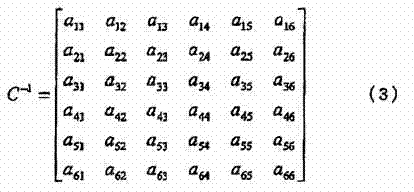
Through arrangement following formula (1)~(3), power that produces practically at the tire installed position and moment of torsion are suc as formula shown in (4).
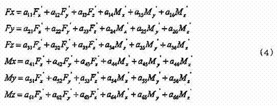
Through using above-mentioned formula, can calculate power and the moment of torsion that produces practically at the tire installed position.And; Maneuvering load applying mechanism 7 is put on practically the long-pending of the load (load that is in other words measured by load measurement device 16) of force transmission member 6 and the distance L that applies position P from the tire installation site to load, the moment of torsion (real moment of torsion) of calculating with using following formula compares.When there is deviation in both, after checking whether force transmission member 6 and load applying mechanism 7 are correctly installed, carry out the calibration of many component meter 5.The calibration of many component meter 5 is for example regulated many component meter 5 and order and is got final product from the equipment (for example amplifier class) of the output amplification of this many component meter 5 etc.
Calibration in this embodiment describes in more detail.Here said calibration is meant asks for transition matrix C
-1The value of 36 compositions.Transition matrix C
-1If confirm, when then after calibration, using many component meter 5 practically, use transition matrix C
-1And ask for real increasing the weight of and moment of torsion (matrix F) from the output signal (matrix E) of many component meter 5.
In this calibration, force transmission member 6 is installed on both allocations with six kinds mounting means, in each mounting means, apply necessary (possible) load, the storage of the output signal of the many component that obtains thus meter 5.Then, after a series of mensuration of each mounting means finishes, ask for transition matrix C
-1Calculating.
For example in the mounting means that produces moment of torsion Mx, ask for each value with being described below.
Fx=0
Fy=0
The output valve of Fz=load measurement device
Mx (output valve of load measurement device) * (distance L)
My=0
Mz=0
The output signal value of the many component meter 5 the when value=load of each composition of matrix E applies.
In the mounting means of mounting means that produces moment of torsion My and generation moment of torsion Mz, also likewise ask for each value with moment of torsion Mx.
In addition, in the mounting means that only produces Fz, ask for each value with being described below.
Fx=0
Fy=0
The output valve of Fz=load measurement device
Mx=0
My=0
Mz=0
The output signal value of the many component meter 5 the when value=load of each composition of matrix E applies.
At the mounting means that only produces Fx, only produce in the mounting means of Fy and also likewise ask for each value with Fz.
Then after a series of mensuration of each mounting means finishes, after promptly the mensuration under six kinds the mounting means is all over, utilizes least square method and try to achieve transition matrix C from the matrix F of trying to achieve and the relation (six relations) of matrix E
-1The value of 36 composition.
In above-mentioned torsion calibration device 1 and calibration steps, can be positioned at apart from the tire installation site be the load of certain distance apply position P below always the pressure cylinder 13 of load applying mechanism 7 is disposed at same position by pin etc.And, can always apply vertical load upwards via loading transfer portion by this pressure cylinder 13 to force transmission member 6 (load is applied position P).Thereby, can on load, not increase error percentage pulley and when rope, so can correctly produce set moment of torsion in the tire installation site as using.In addition, can not produce the friction force of rope and the reversing of wirerope, these and pulley, need not carry out the adjusting of the installation site of pulley in addition.Thus, can be accurately the moment of torsion of many component meter 5 of being arranged at tyre testing apparatus 2 be calibrated.
(second embodiment)
The torsion calibration device 1 and the calibration steps of second embodiment of the present invention then are described.
Like Fig. 2 and shown in Figure 3; The torsion calibration device 1 of second embodiment and calibration steps are different with first embodiment at following point: the torsion calibration device 1 of first embodiment and calibration steps relate to the calibration of the many component meter 5 that is built in mandrel; In relative therewith second embodiment, the many component meter 5 that takes off from tyre testing apparatus 2 self is calibrated.
In the torsion calibration device 1 of second embodiment, have with respect to ground and have the support unit 27 of motionless so fixing many component meter 5 of the substrate of rigidity.This support unit 27 has with the mode towards vertical direction and is fixed in motionless lower component 28 and is installed on the upper-part 29 of the upper end of this lower component 28.This upper-part 29 extends from the cardinal extremity along continuous straight runs of the upper end that is installed on lower component 28, is formed with the installed surface 30 towards vertical direction on its top.On this installed surface 30, the many component meter 5 that takes off from tyre testing apparatus 2 can be installed.
Surface at this many component meter 5 is formed with threaded hole, can be with respect to many component meter 5 along continuous straight runs installing force transferring elements 6 through in this threaded hole, inserting securing member (bolt).
Use the calibration steps of moment of torsion of the torsion calibration device 1 of second embodiment to be done as follows.
Promptly; The moment of torsion that should calibrate for around the x direction the axle moment of torsion Mx the time; Many component meter 5 with respect to the installed surface that is installed on support unit 27 30 is flatly fixing along the y direction with force transmission member 6, likewise force transmission member 6 is up applied vertical load Fz during with first embodiment.So, producing moment of torsion Mx at the center of many component meter 5 around the axle of x direction, its correct calibration becomes possibility.
In addition, the moment of torsion that should calibrate for around the z direction the axle moment of torsion Mz the time, with many component meter 5 around the y direction the axle half-twist state under be installed on installed surface 30.And, likewise force transmission member 6 is flatly installed along the y direction during with the calibration of moment of torsion Mx, force transmission member 6 is applied vertical load.Thus, produce the moment of torsion Mz around the axle of x direction at the center of many component meter 5, its correct calibration becomes possibility.
And then, for around the moment of torsion My of the axle of y direction the time, as shown in Figure 3 at the moment of torsion that should calibrate, with respect to many component meter 5 that force transmission member 6 is flatly fixing along the x direction, likewise up apply vertical load Fz during with the first embodiment mode.Thus, produce the moment of torsion My around the axle of y direction at the center of many component meter 5, its correct calibration becomes possibility.
(summary of embodiment)
If sum up above-mentioned embodiment then be described below.
(1) the present invention is a kind of torsion calibration device of many component meter, can measure to contain along the power of axle to become score value with at least two of moment of torsion of axle of winding perpendicular to this.Above-mentioned torsion calibration device has: rectangular force transmission member; Position with the base end side that links with above-mentioned many component meter and the position that is positioned at the tip side of the position opposition side of above-mentioned base end side are passed to above-mentioned many component meter with the power at the position that inputs to above-mentioned tip side; The load applying mechanism, with respect to the position of the above-mentioned tip side of above-mentioned force transmission member along vertical direction and do not change the imposed load towards ground of power; Calculating part; Applying under the state of the vertical load of vertical direction to the position of above-mentioned tip side from above-mentioned load applying mechanism; Based on winding of measuring by above-mentioned many component meter torque value perpendicular to the axle of the direction of vertical direction; Calculate the real moment of torsion of having got rid of above-mentioned vertical load influence, use the above-mentioned real moment of torsion in aforementioned calculation portion, calculate and carry out the torque calibration of above-mentioned many component meter.
In this mode; Can not produce the friction force of the reversing of the rope that exists in the such calibrating installation in the past of Fig. 4 and wirerope, these and pulley etc.; Need not to regulate the work of the installation site of pulley in addition, can be accurately and efficiently the moment of torsion of many component meter of being arranged at tyre testing apparatus is calibrated.
(2) in above-mentioned torsion calibration device, above-mentioned force transmission member preferably is installed on above-mentioned many component in its length direction towards the mode of horizontal direction.
In this mode, easily along the vertical direction imposed load, it is complicated that the formation of device can not become, and can correctly calibrate moment of torsion.
(3) in above-mentioned torsion calibration device, preferred above-mentioned load applying mechanism has: pressure cylinder is disposed at the below of above-mentioned force transmission member and applies load upwards to above-mentioned force transmission member; Supporting station is used for above-mentioned pressure cylinder is positioned at the below slightly (below slightly of load application point) that above-mentioned load applies the position; With loading transfer portion, the loading transfer that the vertical direction that above-mentioned pressure cylinder is produced makes progress is given above-mentioned force transmission member.As above-mentioned loading transfer portion, can illustration for example contain spheric seating and the formation of the spheric seating of the concavity that contacts with above-mentioned spheric seating point of the convex of the upper end that is arranged at pressure cylinder.
The method of working pressure cylinder and imposed load is more suitable for applying the situation of big load than the method for using counterweight in this wise, and for example tyre testing apparatus can apply the load about maximum 80 kN in this wise.In addition, if use above-mentioned load applying mechanism and loading transfer portion, then can be below the above-mentioned position of the tip side of force transmission member configuration pressure cylinder and force transmission member is applied heavy load along vertical direction.
The tyre testing apparatus of the moment of torsion that the center that above-mentioned torsion calibration device is preferred for utilizing above-mentioned many component instrumentation amount to be installed on the tire of mandrel produces.
(4) the present invention is a kind of torque calibration method of many component meter, and said many component meter is installed on the mandrel of tyre testing apparatus, is arranged at the mandrel housing in order to measure the moment of torsion that produces at the center of tire.In this torque calibration method, use the torsion calibration device of above-mentioned many component meter and many component meter of the state that is arranged at above-mentioned mandrel housing is calibrated.
(5) the present invention is a kind of torque calibration method of many component meter, can become score value to measure with at least two of moment of torsion of axle of winding perpendicular to this to containing along the power of axle.In this torque calibration method, has following step: can the power at the position of the tip side that inputs to rectangular force transmission member being passed to the mode of above-mentioned many component, the position of the base end side of above-mentioned force transmission member is installed on above-mentioned many component meter; To the position of the above-mentioned tip side of above-mentioned force transmission member along vertical direction and do not change power apply vertical load towards ground; Be based under the state that position to the above-mentioned tip side of above-mentioned force transmission member applies above-mentioned vertical load by the torque value of winding of measuring of above-mentioned many component meter, calculate the real moment of torsion of having got rid of above-mentioned vertical load influence perpendicular to the axle of the direction of vertical direction; The above-mentioned real moment of torsion that use is calculated carries out the torque calibration of above-mentioned many component meter.
The present invention is not limited to above-mentioned each embodiment, can be in the scope of the essence that does not change invention to changes that suits such as the shape of each parts, structure, material, combinations.
For example, in the above-described embodiment illustration working pressure cylinder 13 and apply the load applying mechanism 7 of vertical load to the top, but the direction that applies vertical load is not limited to the top.In addition, the direction of such power changed when the mechanism of generation load needed only unlike use rope and pulley, also can not be pressure cylinder 13.For example also can use and counterweight is suspended to force transmission member and applies the load applying mechanism 7 of vertical load towards the below.
In addition; In above-mentioned first embodiment; Mounting torque calibrating installation 1 in tyre testing apparatus; So the load applying mechanism is arranged on the simulated roadway, but also can take off from the mandrel portion that tyre testing apparatus will contain mandrel housing and many component meter, this mandrel portion is installed on second embodiment that kind the support unit with rigidity and carry out calibrating operation.At this moment, load applying mechanism and second embodiment likewise being arranged at rigidity motionless gets final product.
Description of reference numerals
1 ... Torsion calibration device; 2 ... Tyre testing apparatus; 3 ... Main shaft; 4 ... Housing; 5 ... Many component meter; 6 ... Force transmission member; 7 ... The load applying mechanism; 8 ... Calculating part; 9 ... Bolt; 10 ... Recess; 11 ... Accept parts; 13 ... Pressure cylinder; 14 ... Supporting station; 15 ... The pressure cylinder bar; 16 ... The load measurement device; 17 ... Spheric seating; 21 ... Push strut; 22 ... Concave surface; 26 ... Bearing; 27 ... Support unit; 28 ... The lower component of support unit; 29 ... The upper-part of support unit; 30 ... Installed surface L ... Apply the distance of position from the tire installation site to load; P ... Load applies the position; T ... Tire.
Claims (5)
1. the torsion calibration device of component meter more than a kind, said many component meter can be measured to contain along the power of axle and become score value with at least two of moment of torsion of axle of winding perpendicular to this,
Have:
Rectangular force transmission member, position with the base end side that links with above-mentioned many component meter and the position that is positioned at the tip side of the position opposition side of above-mentioned base end side are passed to above-mentioned many component meter with the power at the position that inputs to above-mentioned tip side;
The load applying mechanism, with respect to the position of the above-mentioned tip side of above-mentioned force transmission member along vertical direction and do not change the imposed load towards ground of power;
Calculating part; Be based on from above-mentioned load applying mechanism and apply under the state of the vertical load of vertical direction by the torque value of winding of measuring of above-mentioned many component meter perpendicular to the axle of the direction of vertical direction to the position of above-mentioned tip side; Calculate the real moment of torsion of having got rid of above-mentioned vertical load influence
The above-mentioned real moment of torsion that use is calculated in aforementioned calculation portion and carry out the torque calibration of above-mentioned many component meter.
2. the torsion calibration device of many component meter according to claim 1 is characterized in that,
Above-mentioned force transmission member is installed on above-mentioned many component in its length direction towards the mode of horizontal direction.
3. the torsion calibration device of many component meter according to claim 1 is characterized in that,
Above-mentioned load applying mechanism has:
Pressure cylinder is disposed at the below of above-mentioned force transmission member and applies load upwards to above-mentioned force transmission member;
Supporting station is used for above-mentioned pressure cylinder is positioned at the below slightly that above-mentioned load applies the position;
With loading transfer portion, the loading transfer that the vertical direction that above-mentioned pressure cylinder is produced makes progress is given above-mentioned force transmission member.
4. the torque calibration method of component meter more than a kind, said many component meter is arranged on the mandrel housing of tyre testing apparatus, is used to measure the moment of torsion that produces at the center that is installed in the tire on the mandrel of tyre testing apparatus,
Use the torsion calibration device of the described many component meter of claim 1 and many component meter of the state that is arranged at above-mentioned mandrel housing is calibrated.
5. the torque calibration method of component meter more than a kind can become score value to measure with at least two of moment of torsion of axle of winding perpendicular to this to containing along the power of axle,
Have following step:
Can the power at the position of the tip side that inputs to rectangular force transmission member being passed to the mode of above-mentioned many component, the position of the base end side of above-mentioned force transmission member is installed on above-mentioned many component meter;
To the position of the above-mentioned tip side of above-mentioned force transmission member along vertical direction and do not change power apply vertical load towards ground;
Be based under the state that position to the above-mentioned tip side of above-mentioned force transmission member applies above-mentioned vertical load by the torque value of winding of measuring of above-mentioned many component meter, calculate the real moment of torsion of having got rid of above-mentioned vertical load influence perpendicular to the axle of the direction of vertical direction;
The above-mentioned real moment of torsion that use is calculated carries out the torque calibration of above-mentioned many component meter.
Applications Claiming Priority (3)
| Application Number | Priority Date | Filing Date | Title |
|---|---|---|---|
| JP2010018578A JP5562053B2 (en) | 2010-01-29 | 2010-01-29 | Moment calibration device and calibration method for multi-component force meter |
| JP2010-018578 | 2010-01-29 | ||
| PCT/JP2011/000441 WO2011093078A1 (en) | 2010-01-29 | 2011-01-27 | Moment calibrating apparatus for multi-component force gauge and method of moment calibration |
Publications (2)
| Publication Number | Publication Date |
|---|---|
| CN102713552A true CN102713552A (en) | 2012-10-03 |
| CN102713552B CN102713552B (en) | 2014-10-22 |
Family
ID=44319072
Family Applications (1)
| Application Number | Title | Priority Date | Filing Date |
|---|---|---|---|
| CN201180007419.4A Expired - Fee Related CN102713552B (en) | 2010-01-29 | 2011-01-27 | Moment calibrating apparatus for multi-component force gauge and method of moment calibration |
Country Status (5)
| Country | Link |
|---|---|
| US (1) | US8984928B2 (en) |
| JP (1) | JP5562053B2 (en) |
| CN (1) | CN102713552B (en) |
| TW (1) | TWI475201B (en) |
| WO (1) | WO2011093078A1 (en) |
Cited By (1)
| Publication number | Priority date | Publication date | Assignee | Title |
|---|---|---|---|---|
| CN103033313A (en) * | 2012-12-18 | 2013-04-10 | 上海出入境检验检疫局机电产品检测技术中心 | Electrodeless regulative dynamometer torsion calibrating device |
Families Citing this family (18)
| Publication number | Priority date | Publication date | Assignee | Title |
|---|---|---|---|---|
| CN103499413B (en) * | 2013-10-17 | 2016-02-03 | 中国测试技术研究院力学研究所 | Power lever and lever power standard set-up |
| JP5940041B2 (en) * | 2013-11-07 | 2016-06-29 | 株式会社神戸製鋼所 | Tire testing machine calibration apparatus and tire testing machine calibration method |
| WO2016149649A1 (en) * | 2015-03-18 | 2016-09-22 | Michigan Scientific Corporation | Transducer calibration apparatus |
| CN105181236B (en) * | 2015-05-08 | 2018-04-06 | 重庆市计量质量检测研究院 | Six-dimension force sensor calibration method |
| DE102017108279B8 (en) | 2017-04-19 | 2018-03-29 | Dekra Automobil Gmbh | Mobile calibration device for a brake test bench |
| DK3343193T3 (en) | 2016-12-12 | 2022-09-26 | Dekra Automobil Gmbh | MOBILE CALIBRATING APPARATUS FOR TESTING STAND FOR BRAKES |
| JP6877527B2 (en) * | 2017-02-22 | 2021-05-26 | 三菱重工機械システム株式会社 | Rotating body load measuring device |
| JP2019020179A (en) * | 2017-07-13 | 2019-02-07 | 株式会社エー・アンド・デイ | Measuring device and method for calibrating measuring device |
| EP3460437B1 (en) * | 2017-09-25 | 2021-10-27 | ETA SA Manufacture Horlogère Suisse | Dynamic torque and/or force calibration device |
| WO2019139895A1 (en) | 2018-01-09 | 2019-07-18 | Innovusion Ireland Limited | Lidar detection systems and methods that use multi-plane mirrors |
| WO2019199796A1 (en) | 2018-04-09 | 2019-10-17 | Innovusion Ireland Limited | Compensation circuitry for lidar receiver systems and method of use thereof |
| CN114114295B (en) | 2018-06-15 | 2025-06-06 | 图达通智能美国有限公司 | LIDAR system and method for focusing on a range of interest |
| US11486786B2 (en) | 2018-11-26 | 2022-11-01 | Gary Childers | Torque testing and calibration system |
| CN112857667B (en) * | 2021-03-15 | 2022-10-14 | 合肥工业大学 | A hybrid excitation dynamic calibration method for a strain-type six-dimensional force sensor |
| WO2022225859A1 (en) | 2021-04-22 | 2022-10-27 | Innovusion, Inc. | A compact lidar design with high resolution and ultra-wide field of view |
| CN216356147U (en) | 2021-11-24 | 2022-04-19 | 图达通智能科技(苏州)有限公司 | Vehicle-mounted laser radar motor, vehicle-mounted laser radar and vehicle |
| GB2616076B (en) * | 2022-02-28 | 2024-04-10 | Aptiv Tech Ltd | Plugging force test apparatus |
| CN120404463A (en) * | 2025-07-03 | 2025-08-01 | 中国计量科学研究院 | Calibration method of compression-shear testing machine for seismic isolation device based on three-axis force sensor |
Citations (6)
| Publication number | Priority date | Publication date | Assignee | Title |
|---|---|---|---|---|
| JPS6461643A (en) * | 1987-09-02 | 1989-03-08 | Fujitsu Ltd | Calibrating method for force detector |
| US5020357A (en) * | 1989-08-18 | 1991-06-04 | N. K. Biotechnical Engineering Company | Calibration stand for sensor |
| JPH0621834B2 (en) * | 1986-01-09 | 1994-03-23 | 日立建機株式会社 | Verification device for load detector |
| JP2003004598A (en) * | 2001-04-20 | 2003-01-08 | Nissho Denki Kk | Method and apparatus for measuring tire rolling resistance |
| CN2604674Y (en) * | 2003-03-27 | 2004-02-25 | 洛阳轴研科技股份有限公司 | Bearing friction torque measuring instrument |
| CN100549649C (en) * | 2008-01-30 | 2009-10-14 | 中国科学院合肥物质科学研究院 | A kind of scaling method that is used for six-dimension force sensor calibration device |
Family Cites Families (5)
| Publication number | Priority date | Publication date | Assignee | Title |
|---|---|---|---|---|
| JPS59151032A (en) | 1983-02-18 | 1984-08-29 | Hitachi Ltd | Force sensor evaluation and calibration jig |
| JPH0621834A (en) | 1992-07-03 | 1994-01-28 | Toshiba Corp | Selective calling receiver |
| US6484574B1 (en) * | 2000-11-08 | 2002-11-26 | Hünter Engineering Company | Wheel balancer apparatus with improved imbalance correction weight positioning |
| US6629446B2 (en) * | 2001-01-08 | 2003-10-07 | The United States Of America As Represented By The Administrator Of The National Aeronautics And Space Administration | Single vector calibration system for multi-axis load cells and method for calibrating a multi-axis load cell |
| DE10145867A1 (en) * | 2001-09-18 | 2003-04-03 | Deutz Ag | Method for calibrating a performance brake for internal combustion engines |
-
2010
- 2010-01-29 JP JP2010018578A patent/JP5562053B2/en not_active Expired - Fee Related
-
2011
- 2011-01-27 CN CN201180007419.4A patent/CN102713552B/en not_active Expired - Fee Related
- 2011-01-27 WO PCT/JP2011/000441 patent/WO2011093078A1/en not_active Ceased
- 2011-01-27 US US13/522,573 patent/US8984928B2/en not_active Expired - Fee Related
- 2011-01-28 TW TW100103447A patent/TWI475201B/en not_active IP Right Cessation
Patent Citations (6)
| Publication number | Priority date | Publication date | Assignee | Title |
|---|---|---|---|---|
| JPH0621834B2 (en) * | 1986-01-09 | 1994-03-23 | 日立建機株式会社 | Verification device for load detector |
| JPS6461643A (en) * | 1987-09-02 | 1989-03-08 | Fujitsu Ltd | Calibrating method for force detector |
| US5020357A (en) * | 1989-08-18 | 1991-06-04 | N. K. Biotechnical Engineering Company | Calibration stand for sensor |
| JP2003004598A (en) * | 2001-04-20 | 2003-01-08 | Nissho Denki Kk | Method and apparatus for measuring tire rolling resistance |
| CN2604674Y (en) * | 2003-03-27 | 2004-02-25 | 洛阳轴研科技股份有限公司 | Bearing friction torque measuring instrument |
| CN100549649C (en) * | 2008-01-30 | 2009-10-14 | 中国科学院合肥物质科学研究院 | A kind of scaling method that is used for six-dimension force sensor calibration device |
Cited By (1)
| Publication number | Priority date | Publication date | Assignee | Title |
|---|---|---|---|---|
| CN103033313A (en) * | 2012-12-18 | 2013-04-10 | 上海出入境检验检疫局机电产品检测技术中心 | Electrodeless regulative dynamometer torsion calibrating device |
Also Published As
| Publication number | Publication date |
|---|---|
| TWI475201B (en) | 2015-03-01 |
| JP5562053B2 (en) | 2014-07-30 |
| JP2011158295A (en) | 2011-08-18 |
| TW201140016A (en) | 2011-11-16 |
| WO2011093078A1 (en) | 2011-08-04 |
| US20120297858A1 (en) | 2012-11-29 |
| US8984928B2 (en) | 2015-03-24 |
| CN102713552B (en) | 2014-10-22 |
Similar Documents
| Publication | Publication Date | Title |
|---|---|---|
| CN102713552A (en) | Moment calibrating apparatus for multi-component force gauge and method of moment calibration | |
| KR101267706B1 (en) | Calibration method for multi-component force measuring spindle unit used in tire testing machine | |
| CN204128889U (en) | A kind of beam bending experiment loading unit | |
| CN104807630A (en) | H-shaped vertical axis wind turbine blade static force structure test device and method | |
| CN107782481B (en) | Ground calibration method for torsion arm load of double-wheel strut type nose landing gear | |
| CN103487264A (en) | Testing device for single-wheel traction performance | |
| CN105466630A (en) | A torque sensor calibrating method | |
| US20100024565A1 (en) | Method of considering the dynamic behavior of a movable member of a machine for performing a wheel fatigue test | |
| CN106289622A (en) | A kind of device and method measuring high-strength bolt auxiliary connection torque coefficient | |
| CN112504589A (en) | Helicopter composite material main blade airfoil section static strength test system and method | |
| CN107063845B (en) | Coordinated loading device and measuring method for axial force and bending moment of main material angle steel of power transmission tower | |
| CN106092582A (en) | Hub bearing unit torque rigidity test device and method | |
| CN112525481A (en) | Six-component high-precision micro rolling torque measuring device and measuring method | |
| EP0244173A2 (en) | Improvements in dynamometers | |
| CN1727861A (en) | Device for calibrating parallel force transducer in six dimensions | |
| CN202522369U (en) | Engineering vehicle torque sensor calibration device | |
| CN203203750U (en) | A calibrating apparatus of a six-component sensor | |
| CN105606380B (en) | A kind of tire six square phase test device for eliminating unbalance loading | |
| CN110082015A (en) | A kind of anchoring dynamic search hydraulic steel gate hoisting capacity dynamic monitor and monitoring method | |
| CN205246358U (en) | Eliminate six component testing arrangement on tire of unbalance loading | |
| CN113959622A (en) | A five-component test device for measuring the multi-component force of solid rocket motors | |
| KR20060132859A (en) | Platform balance for wind tunnel | |
| CN107782492A (en) | A kind of modular mechanical shoulder joint torque sensor calibrating platform | |
| CN102788655A (en) | Blower load measuring device and system and blower control system | |
| CN105067364A (en) | Overall strength test method and device for wind driven generator |
Legal Events
| Date | Code | Title | Description |
|---|---|---|---|
| C06 | Publication | ||
| PB01 | Publication | ||
| C10 | Entry into substantive examination | ||
| SE01 | Entry into force of request for substantive examination | ||
| C14 | Grant of patent or utility model | ||
| GR01 | Patent grant | ||
| CF01 | Termination of patent right due to non-payment of annual fee | ||
| CF01 | Termination of patent right due to non-payment of annual fee |
Granted publication date: 20141022 Termination date: 20220127 |