CN102714101A - Method and device for determining wear of a contact element - Google Patents
Method and device for determining wear of a contact element Download PDFInfo
- Publication number
- CN102714101A CN102714101A CN2010800623290A CN201080062329A CN102714101A CN 102714101 A CN102714101 A CN 102714101A CN 2010800623290 A CN2010800623290 A CN 2010800623290A CN 201080062329 A CN201080062329 A CN 201080062329A CN 102714101 A CN102714101 A CN 102714101A
- Authority
- CN
- China
- Prior art keywords
- value
- loss
- values
- arc
- contribution
- Prior art date
- Legal status (The legal status is an assumption and is not a legal conclusion. Google has not performed a legal analysis and makes no representation as to the accuracy of the status listed.)
- Granted
Links
Images
Classifications
-
- H—ELECTRICITY
- H01—ELECTRIC ELEMENTS
- H01H—ELECTRIC SWITCHES; RELAYS; SELECTORS; EMERGENCY PROTECTIVE DEVICES
- H01H1/00—Contacts
- H01H1/0015—Means for testing or for inspecting contacts, e.g. wear indicator
-
- H—ELECTRICITY
- H01—ELECTRIC ELEMENTS
- H01H—ELECTRIC SWITCHES; RELAYS; SELECTORS; EMERGENCY PROTECTIVE DEVICES
- H01H1/00—Contacts
- H01H1/0015—Means for testing or for inspecting contacts, e.g. wear indicator
- H01H2001/0031—Means for testing or for inspecting contacts, e.g. wear indicator by analysing radiation emitted by arc or trace material
-
- H—ELECTRICITY
- H01—ELECTRIC ELEMENTS
- H01H—ELECTRIC SWITCHES; RELAYS; SELECTORS; EMERGENCY PROTECTIVE DEVICES
- H01H33/00—High-tension or heavy-current switches with arc-extinguishing or arc-preventing means
- H01H33/60—Switches wherein the means for extinguishing or preventing the arc do not include separate means for obtaining or increasing flow of arc-extinguishing fluid
- H01H33/66—Vacuum switches
- H01H33/664—Contacts; Arc-extinguishing means, e.g. arcing rings
- H01H33/6643—Contacts; Arc-extinguishing means, e.g. arcing rings having disc-shaped contacts subdivided in petal-like segments, e.g. by helical grooves
Landscapes
- Arc-Extinguishing Devices That Are Switches (AREA)
- Keying Circuit Devices (AREA)
- Driving Mechanisms And Operating Circuits Of Arc-Extinguishing High-Tension Switches (AREA)
Abstract
Description
技术领域 technical field
本发明涉及电气开关、尤其是用于高或中压的开关设备领域。本发明方面涉及用于确定这种开关的接触元件的耗损的方法。本发明的另外方面涉及用于电气开关的电子单元。 The invention relates to the field of electrical switches, in particular switchgear for high or medium voltage. An aspect of the invention relates to a method for determining the wear of a contact element of such a switch. A further aspect of the invention relates to an electronic unit for an electrical switch.
背景技术 Background technique
功率开关经常受到磨耗,因此应该定期监控和维护。尤其是在开关操作(例如保护断开)情况下出现的电弧导致接触件的材料耗损并且由此造成巨大磨耗。在未高成本地拆开和断开功率的情况下,触点一般不能被简单地检查。因此,通常进行周期性功率开关维护,必要时,当对于高电流的保护断开出现时提前进行维护。因此,通常太经常对开关进行维护。维护造成可避免的成本,并且造成额外风险,即在维护时可造成损害。然而另一方面,在维护间隔太大情况下存在磨耗或者触点耗损不能提前被识别的风险。在此,存在功能故障风险、至少存在开关功率损耗风险。 Power switches are constantly subject to wear and should therefore be regularly monitored and maintained. In particular, arcing that occurs during switching operations (for example, a protective opening) leads to material loss of the contacts and thus causes considerable wear. The contacts generally cannot be easily inspected without costly disassembly and disconnection of power. Therefore, periodic power switch maintenance is usually performed, if necessary, in advance when a protective trip for high currents occurs. As a result, maintenance is often performed on switches too often. Maintenance creates avoidable costs and creates an additional risk that damage can be caused during maintenance. On the other hand, however, if the maintenance intervals are too large, there is a risk that wear or contact wear cannot be detected in advance. Here, there is a risk of a malfunction, at least a loss of switching power.
因此,更可靠地确定接触件的耗损是值得向往的。然而,该耗损是很难测量或者预测的,因为它受大量因素影响。一般认为触点耗损是在打开功率开关时出现电弧的情况下由累积的能量转换(损耗功率)引起的。因此,仅计算功率开关中出现的故障数目不能得出关于触点耗损的精确估计。 Therefore, a more reliable determination of contact wear is desirable. However, this loss is difficult to measure or predict because it is affected by a large number of factors. Contact wear is generally believed to be caused by accumulated energy transfer (loss power) in the event of an arc when the power switch is turned on. Therefore, merely counting the number of faults occurring in a power switch cannot yield an accurate estimate of contact wear.
EP 1475813 A1描述了用于确定用于高或中压的电气开关设备中的触点耗损的方法,其中开关操作期间流经开关的接触电流借助于电流互感器被检测并且关于触点耗损进行分析。为了确定表征触点耗损的状态变量,首先电流互感器的电流测量信号作为时间函数被测量,在期望的接触电流和电流测量信号之间出现偏差时探测出存在测量误差,并且在探测到测量误差时从电流测量信号中确定至少一个特征性的电流值并且至少一个特征性的电流值用于确定状态变量。DE 10204849 A1也描述了用于确定触点耗损的方法。 EP 1475813 A1 describes a method for determining contact wear in electrical switching devices for high or medium voltage, wherein the contact current flowing through the switch during switching operation is detected by means of a current transformer and analyzed with respect to contact wear . In order to determine the state variable characterizing the contact wear, first the current measurement signal of the current transformer is measured as a function of time, a measurement error is detected when a deviation occurs between the desired contact current and the current measurement signal, and when a measurement error is detected At least one characteristic current value is determined from the current measurement signal and the at least one characteristic current value is used to determine the state variable. DE 10204849 A1 also describes a method for determining contact wear.
然而,已知用于确定耗损的方法就其可靠性而言仍待改善。也值得向往的是获取在大量不同开关情况下提供可靠结果的方法,使得所述可靠结果适合于自动(远程)诊断和维护。以此方式能够减少高成本的维护工作。同时能够实现可靠的连续状态监控。在问题和耗损严重前识别和排除它们也是值得向往的。 However, the known methods for determining wear still leave room for improvement in terms of their reliability. It would also be desirable to have a method that provides reliable results under a large number of different switching situations, making the reliable results suitable for automatic (remote) diagnostics and maintenance. Costly maintenance work can be reduced in this way. At the same time, reliable continuous condition monitoring is possible. It is also desirable to identify and troubleshoot problems and wear and tear before they become serious.
发明内容 Contents of the invention
因此,为了至少改进上述点中的至少一些,提出了按照权利要求1所述的方法、按照权利要求13所述的开关控制装置和按照权利要求14所述的开关设备。本发明的另外优点、特征、方面和细节以及优选实施方式和本发明的特别方面从从属权利要求、描述和附图中得出。
Therefore, in order to improve at least some of the above points, a method according to
按照本发明的一个方面,提供了用于确定电气开关(例如真空开关)、尤其是用于高或中压的开关设备的接触元件的耗损的方法供使用。该方法包括电气值的检测,这些电气值作为时间的函数表示与在开关操作期间在开关上出现的电弧相关的电气变量,其中例如能够作为连续函数或具有离散采样值的数据序列(矢量)检测电气值,电气值也能够包括虚拟值,例如(部分)模拟、内插、或拟合的值,在所述情况下虚拟值被检测到。电气值例如能够是电流值,其作为时间的函数表示在开关操作期间流经开关的接触电流。该方法进一步包括从多个耗损贡献值中计算表示接触元件的耗损的耗损值,其中在使用多个耗损贡献计算规则的情况下从所检测电气值的多个值子集中计算耗损贡献值,使得根据相应耗损贡献计算规则从相应值子集中计算每个耗损贡献值,并且其中至少两个耗损贡献计算规则彼此有区别。在此,如此理解值子集,使得它也能够包括所有所检测电气值。 According to one aspect of the invention, a method for determining the wear of a contact element of an electrical switch, such as a vacuum switch, in particular a switchgear for high or medium voltage, is provided for use. The method comprises the detection of electrical values representing, as a function of time, electrical variables associated with the occurrence of an arc across the switch during switching operation, wherein it can be detected, for example, as a continuous function or as a data sequence (vector) with discrete sampled values Electrical values, which can also comprise virtual values, eg (partially) simulated, interpolated, or fitted values, in which case virtual values are detected. The electrical value can be, for example, a current value which, as a function of time, represents the contact current flowing through the switch during switching operation. The method further comprises calculating a loss value representative of the loss of the contact element from a plurality of loss contribution values, wherein the loss contribution value is calculated from a plurality of value subsets of the detected electrical values using a plurality of loss contribution calculation rules such that Each wear contribution value is calculated from a respective subset of values according to a respective wear contribution calculation rule, and at least two of the wear contribution calculation rules are differentiated from each other. In this case, the value subset is understood in such a way that it can also include all detected electrical values.
按照本发明另一方面,提供了用于电气开关(例如真空开关)、尤其是用于高或中压的开关设备的电子单元、尤其是控制和/或监控系统供使用。该电子单元包括用于获得电气值(例如电流值)的值输入模块,这些电气值作为时间的函数表示与在开关操作期间在开关上出现的电弧相关的电气变量。因此,能够配备该值输入模块例如以便从值测量设备获取所检测电气值,然而也可能是由通过所检测电气值的(部分)模拟或内插等等。该电子单元进一步包括耗损确定模块,其具有计算单元和带有能够由计算单元执行的程序代码的数据存储器。该程序代码包括多个耗损贡献计算规则(它们被设置用于从所检测电气值的相应值子集中计算相应耗损贡献值,其中至少两个耗损贡献计算规则彼此有区别),以及用于从耗损贡献值中计算表示接触元件的耗损的耗损值的耗损值计算例程。该程序代码尤其是包括用于实施在此所述的任一方法的规则。 According to a further aspect of the invention, an electronic unit, in particular a control and/or monitoring system, for an electrical switch, such as a vacuum switch, in particular a switchgear for high or medium voltage, is provided for use. The electronic unit comprises value input modules for obtaining electrical values, such as current values, representing as a function of time electrical variables related to the arc occurring on the switch during the switching operation. Thus, the value input module can be equipped, for example, to obtain the detected electrical value from a value measuring device, but also possibly by (partial) simulation or interpolation of the detected electrical value or the like. The electronics unit further comprises a wear determination module having a computing unit and a data memory with a program code executable by the computing unit. The program code includes a plurality of loss contribution calculation rules arranged to calculate respective loss contribution values from respective subsets of values of the detected electrical values, wherein at least two loss contribution calculation rules are distinguished from The loss value calculation routine in Contribution Value calculates a loss value representing the loss of a contact element. In particular, the program code includes rules for carrying out any of the methods described here.
本发明也涉及用于实施所公开方法的装置并且也包括用于实施相应各方法步骤的装置部件。这些方法步骤能够通过硬件组件、通过借助于相应软件编程的电脑、通过两者的组合、或以任一其它方式得到实施。此外,本发明也针对如下方法,相应描述的装置按照所述方法工作。本发明包含用于实施装置的每种功能的方法步骤。 The invention also relates to a device for carrying out the disclosed method and also includes device components for carrying out the respective method steps. The method steps can be implemented by hardware components, by a computer programmed with corresponding software, by a combination of both, or in any other way. Furthermore, the invention is also directed to methods according to which a correspondingly described device operates. The invention includes method steps for carrying out each function of the device.
附图说明 Description of drawings
另外,根据附图中示出的实施例对本发明进行阐述,从这些实施例中得出另外的优势部分和变型方案。其中: In addition, the invention is explained on the basis of the exemplary embodiments shown in the drawings, from which further advantages and variants emerge. in:
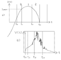
图1a作为时间的函数示出在开关操作期间出现的被测量电流的图; Figure 1a shows a graph of the measured current occurring during switching operation as a function of time;
图1b作为时间的函数示出在开关操作期间出现的被测量电压(更准确地说:电弧电压)的图; Figure 1 b shows a graph of the measured voltage (more precisely: arc voltage) occurring during switching operation as a function of time;
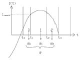
图2作为时间的函数示出在开关操作期间出现的电流的图,从该图中推导出开关操作的不同电弧相位; Figure 2 shows a graph of the currents occurring during switching operation as a function of time, from which graph the different arc phases of the switching operation are deduced;
图3a和3b示出相应可能的辅助函数,它们能够用于按照本发明计算耗损值;以及 Figures 3a and 3b show corresponding possible auxiliary functions which can be used for calculating loss values according to the invention; and
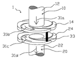
图4示出电气开关的接触元件。 Figure 4 shows a contact element of an electrical switch.
具体实施方式 Detailed ways
在以下描述的实施方式中,各方面和特征可模块式地与其它实施方式的方面和特征组合。通过这种组合能够重新获得其它的实施方式,它们也被视为属于本公开。下文描述用于唯一相的开关。一般而言,存在三个带有相应附属功率开关的相。那么,按照在此描述的任一方面,通常能够彼此独立地确定相应耗损。 In the embodiments described below, aspects and features can be modularly combined with aspects and features of other embodiments. Other embodiments can be obtained through this combination, and they are also considered to belong to the present disclosure. The switches for the only phase are described below. In general, there are three phases with corresponding associated power switches. Then, according to any of the aspects described herein, the respective losses can generally be determined independently of each other.
以下主要描述这种实施方式,在这些实施方式中电流值被检测,并且从电流值中计算耗损贡献(Abnutzungsbeitrag)。一般也能够从另外的电气值中计算耗损贡献。在此,任一种与在开关操作期间在开关上出现的电弧相关的变量值都被理解为电气值。这些电气值尤其能够是电流值、电压值和/或它们的组合(例如电弧功率值,其由电流和电压的乘积形成)。在此所述的基于电流的计算规则也可类似地基于这种另外电气值来应用,其方式是在相同计算规则中将电流值I替换成另外的电气值。 The following mainly describes embodiments in which current values are detected and a loss contribution is calculated from the current values. In general, the loss contribution can also be calculated from other electrical values. Any variable value that is related to the arc that occurs at the switch during switching operation is to be understood as an electrical value here. These electrical values can in particular be current values, voltage values and/or combinations thereof (for example arc power values which are formed from the product of current and voltage). The current-based calculation rules described here can also be applied analogously based on such other electrical values by substituting the current value I for the other electrical value in the same calculation rules.
电气开关,例如作为功率开关应用在用于高或中压的开关设备中,通常具有两个或更多个接触件。在开关闭合的情况下,这些接触件彼此是直接能导电接触的。在打开开关的情况下接触件彼此离开且分开,使得不再有电流能够从一个接触件流动到另一接触件。当在开关过程期间有电流流动时,那么在将两个接触件彼此分开期间电流流动不会立刻完全中断,而是在两个接触件之间产生电弧,该电弧在一定时间内继续载有电流。这种电弧也在功率开关(也就是,设计用于在负载下开关的特殊开关类型)中出现,并且特别是在高压(也就是说大于50 kV、例如50-800 kV的电压)或中压(也就是说5 kV至50 kV的电压)功率开关中。 Electrical switches, such as are used as power switches in switching devices for high or medium voltage, usually have two or more contacts. When the switch is closed, the contacts are in direct conductive contact with one another. When the switch is opened, the contacts move away from each other and separate such that no current can flow from one contact to the other. When a current flows during the switching process, then the current flow is not immediately completely interrupted during the separation of the two contacts from each other, but an arc is created between the two contacts which continues to carry the current for a certain time . Such arcs also occur in power switches (that is, special switch types designed to switch under load), and especially at high voltages (that is, voltages greater than 50 kV, such as 50-800 kV) or medium voltage (That is to say, a voltage of 5 kV to 50 kV) in the power switch.
在图4中以真空功率开关为例示出这种带有电弧在负荷下的开关过程。该真空功率开关1具有第一接触件10和第二接触件20。接触件10、20分别具有杆12、22和布置在杆的远端的接触盘14、24。每个接触件10、20的接触盘14、24分别具有接触表面,该接触表面在开关闭合情况下直接与相应另一接触件的相应接触表面接触。两个接触件10、20限定了开关轴,它们为了打开开关是相对彼此可沿着所述开关轴活动的。在图4中该轴是垂直的。
Such a switching process with an arc under load is shown in FIG. 4 using the example of a vacuum power switch. The
在图4中示出了打开期间的开关1,并且接触件10、20已沿着开关轴彼此分开。在图4中电流仍未完全完成中断,并且在接触件10和20之间形成电弧33。通过电弧33传达:仍有电流从第一接触件10流至第二接触件。电流流经杆12(电流路径31a)、流经接触盘14(电流路径31b),然后流经电弧33、并流经接触盘24(电流路径31c)且流经杆22。在电弧影响下,接触件的材料被侵蚀(该材料通常形成电弧的等离子体),这导致接触件的耗损。
In Fig. 4 the
在示出例子中,接触件10、20形成为TMF型。TMF型表示接触件如此形成,使得开关电流在开关过程中引起主要横向的磁场(垂直于一般的电流流动方向或者电弧的主方向,也就是平行于通过接触表面14和24限定的面)。在此,这通过接触盘14和24中的槽实现。这些槽在盘中给出的电流31b、31c的电流流动方向使得该电流感应引起横向磁场(在图4中在水平平面中)。在图4中示出的开关是螺旋型的(也就是说带有形成为螺旋形的槽)。另外的接触件形状也是可能的。用于TMF型开关的一可能备选形状例如是杯状(cup-shaped)接触件。
In the example shown, the
在图4中示出的开关是真空功率开关(也就是说在预计其中有电弧的开关室中带有低压,尤其是带有高真空)。即便本发明的某些优点对于例如中或高压范围的真空功率开关能够特别好地被实现,但是本发明也并不限于这种开关。本发明的方面同样也能够涉及例如保护气体功率开关,在该保护气体功率开关中开关室填充有保护气体,例如SF6。 The switch shown in FIG. 4 is a vacuum power switch (that is to say with a low pressure, in particular a high vacuum, in the switching chamber in which arcing is expected). Even though certain advantages of the invention can be realized particularly well eg for vacuum power switches in the medium or high voltage range, the invention is not limited to such switches. Aspects of the invention can also relate, for example, to a shielding gas power switch in which the switching chamber is filled with a shielding gas, for example SF 6 .
开关、尤其是功率开关中的难点是接触件(例如图4中的接触件10、20)由于电弧(图4中的33)引起的耗损。通过耗损或者随之而来的开关磨耗引起的问题在上面已经得到进一步说明。出于上述原因值得向往的是,尽可能准确地确定磨耗。
A difficulty in switches, especially power switches, is the wear of contacts (such as
在此为了图示目的提及的方法为了该目的规定了例如以下形式的电流积分,以便确定磨耗: The method mentioned here for illustration purposes provides for this purpose a current integration of the form, for example, in order to determine the wear:

在此,磨耗通过厚度d给出(单位为mm),在开关过程期间材料由于电弧而从接触件的接触表面上被侵蚀了厚度d。在此,I(t)作为时间t的函数来表示在开关操作期间流经开关的接触电流,也就是说在时间t时流经电弧33的电流,见图4。k和α是常数,它们例如能够通过模型确定或凭经验确定。(1)中的时间积分涉及其间存在电弧的全部开关时间。在此,如在方程式(1)中的积分也应表达离散电流值的总和,该总和适合地接近这种积分。
In this case, the wear is given by the thickness d (in mm) by which the material is eroded from the contact surface of the contact piece during the switching process due to the arc. Here, I(t) as a function of time t represents the touch current flowing through the switch during switching operation, that is to say the current flowing through the
然而,计算规则(1)尤其是对于中或高开关电流提供不准确的结果。当对于低开关电流校正参数k和α时,那么利用规则(1)对于高开关电流和长电弧持续时间(相位长度0.75 π和更长)有高估磨耗的趋势,并且对于中等的或高的开关电流和短电弧持续时间(相位长度0.25 π和更短)有低估磨耗的趋势。因此提出了对于更现实的或者更准确的规则的问题,以便也对于宽范围的开关电流和电弧持续时间确定磨耗d。出于该目的,能够促使人们通过更复杂的表达(利用更多适合经验的参数)替代(1)中的被积函数。然而利用这种方式可实现的准确性同样也受限并且不能证明适合的参数数目的增加是有效的。 However, calculation rule (1) provides inaccurate results especially for medium or high switching currents. When correcting the parameters k and α for low switching currents, then using rule (1) there is a tendency to overestimate wear for high switching currents and long arc durations (phase lengths 0.75 π and longer), and for moderate or high Switching currents and short arc durations (phase lengths 0.25 π and shorter) tend to underestimate wear. The problem therefore arises of a more realistic or more accurate rule in order to determine the wear d also for a wide range of switching currents and arc durations. For this purpose, one can be motivated to replace the integrand in (1) by a more complex expression (with more empirically appropriate parameters). However, the accuracy achievable in this way is likewise limited and an increase in the number of suitable parameters cannot be justified.
按照本发明,通过以下用于确定接触元件的耗损的方法,这些难点至少得到降低:首先,作为时间t的函数来检测表示在开关操作期间流经开关的接触电流的电流值I(t)。电流值I(t)能够作为连续函数或具有离散采样值的数据序列(矢量)被检测。被采样的电流值不仅能够包括被测量的值,而且能够包括虚拟值,例如基于测量值和/或合适模型模拟、内插或拟合的值。该电流例如能够假定为正弦形,并且能够根据测量的值调整信号的振幅和相位,以及,如果需要的话,还有频率,使得正弦形电流与被测量的值产生良好的一致性。 According to the invention, these difficulties are at least reduced by the following method for determining the wear of the contact element: first, a current value I(t) representing the contact current flowing through the switch during switching operation is detected as a function of time t. The current value I(t) can be detected as a continuous function or as a data sequence (vector) with discrete sampled values. The sampled current values can include not only measured values, but also virtual values, eg simulated, interpolated or fitted values based on measured values and/or suitable models. The current can for example be assumed to be sinusoidal, and the amplitude and phase of the signal, and, if necessary, the frequency, can be adjusted according to the measured value so that a good agreement is produced between the sinusoidal current and the measured value.
然后,从复数N个耗损贡献值di中计算耗损值d,i=l ..N(例如作为这些耗损贡献值的总和)。耗损贡献值di又是在使用多个耗损贡献计算规则fi的情况下从所检测的电流值I(t)的多个电流值子集中计算的,使得根据相应耗损贡献计算规则fi从相应电流值子集中计算每个耗损贡献值(电流值子集也能够包括所有所检测电流值,因此能够是真正的子集或非真正的子集)。在此,至少两个耗损贡献计算规则彼此有区别(作为函数或者图)。 Then, the loss value d, i=l..N is calculated from the complex number N of loss contribution values d i (eg as a sum of these loss contribution values). The loss contribution values d i are in turn calculated from a plurality of subsets of current values of the detected current value I(t) using a plurality of loss contribution calculation rules f i such that according to the corresponding loss contribution calculation rules f i from Each loss contribution value is calculated in a corresponding subset of current values (a subset of current values can also include all detected current values and thus can be a true subset or a non-true subset). In this case, at least two loss contribution calculation rules differ from one another (as a function or as a graph).
本发明一方面基于这样的认识,即在开关过程期间出现不同的电弧相位。这些电弧相位大致在时间上相继。这些不同的电弧相位导致接触件的相应不同的耗损,也就是说耗损根据电弧相位以不同的方式取决于电流:在例如扩散电弧导致接触件的不同部分的更均匀且少的耗损时,静止收缩(zusammengeschnürt)电弧(导致接触件的受限部分的严重耗损,并且由此对于耗损是整体相关的。 The invention is based on the one hand on the recognition that different arc phases occur during the switching process. These arc phases are approximately sequential in time. These different arc phases lead to correspondingly different wear of the contact, that is to say the wear depends on the current in a different manner depending on the arc phase: static contraction while, for example, a diffuse arc leads to a more uniform and less wear of the different parts of the contact (zusammengeschnürt) arc (leads to severe wear of a limited part of the contact and is therefore integrally relevant for wear.
按照本发明的方法允许有利地将不同电弧相位对接触元件的耗损的贡献计算成相应的专有耗损贡献值。每个耗损贡献值能够借助于对于相应电弧相位而言专门的耗损贡献计算规则来计算。为此有利的是如此选择电流值子集和/或耗损贡献计算规则,使得特定的被检测电流值分别根据其在哪些电弧相位中出现而导致相应不同的耗损贡献。 The method according to the invention advantageously allows the contribution of the different arc phases to the wear of the contact element to be calculated as a corresponding specific loss contribution. Each loss contribution value can be calculated by means of a loss contribution calculation rule specific to the respective arc phase. To this end, it is advantageous to select the current value subset and/or the loss contribution calculation rule in such a way that a particular detected current value results in a correspondingly different loss contribution depending on which arc phases they occur in each case.
对此,首先确定相应电流值子集。属于相应电弧相位的那些电流值能够确定为电流值子集。为此,能够为相应电弧相位确定时间间隔(例如为第i个电弧相位确定ti至t'i的时间间隔


各电弧相位之间的时间界限可能是有些不清晰的,在它们之间有转变时间段。然而,人们能够至少近似地为相位的界限(开始或结束)确定界限时间点,也就是ti用于第i个电弧相位的开始或t'i用于结束。一般这种界限时间点能够是或者用于电弧开始的开始时间点(或者第一电弧相位),或者是用于从一个相位到相应下一个相位的转变的转变时间点,或者是用于电弧的结束(或者最后的电弧相位)的结束时间点。因此,比起这种,转变时间点同样不涉及电弧的开始或结束,因为在此没有不同的电弧相位会互相穿入。 The time boundaries between the various arc phases may be somewhat unclear, with transition periods between them. However, one can at least approximately determine a limit time point for the limit (start or end) of the phase, ie t i for the start of the ith arc phase or t′ i for the end. Generally such a limit time point can be either the start time point for the start of the arc (or the first arc phase), or the transition time point for the transition from one phase to the corresponding next phase, or the The end time of the end (or last arc phase). Thus, in contrast to this, the transition time also does not concern the start or end of the arc, since here no different arc phases can intersect one another.
在TMF开关中电弧的类型和运动可通过在特殊成型的接触件上的观察检测到。在此,在示例性的TMF开关中可从彼此间区分出以下不同的电弧相位: The type and movement of arcs in TMF switches can be detected by observation on specially shaped contacts. In this case, the following different arc phases can be distinguished from each other in the exemplary TMF switch:
具有扩散电弧的相位:该电弧在空间上沿着接触件上宽的面分布; Phase with diffuse arc: the arc is spatially distributed along a wide surface on the contact;
具有收缩静止电弧的相位:该电弧被收窄成窄的区域,从该区域起它垂直于接触表面延伸,并且是静止的,也就是说几乎不沿着接触表面运动; Phase with constricted stationary arc: the arc is narrowed into a narrow region from which it extends perpendicularly to the contact surface and is stationary, that is to say hardly moves along the contact surface;
带有收缩运动电弧的相位:电弧继续收窄成窄的区域,然而沿着接触表面以高速度(也就是说以明显高于之前相位中的速度)运动。在最后的相位完成后电弧熄灭(在完全熄灭前可能具有另一带有扩散电弧的相位)。分别根据开关和接触件的构造,这些相位能够与上述相位有区别,并且能够给出与上述相位相比更多的相位或更少的相位或与之类型不同的相位。 Phase with constricting moving arc: The arc continues to narrow into a narrow area, but moves along the contact surface at a high speed (that is to say at a speed significantly higher than in the previous phase). The arc is extinguished after the last phase is complete (possibly another phase with a spreading arc before complete extinction). Depending on the configuration of the switch and the contacts, respectively, these phases can differ from the above-mentioned phases and can provide more phases or fewer phases than the above-mentioned phases or phases of a different type therefrom.
因此,在上述例子中,用于扩散电弧的开始的开始时间点t0(或,更确切地说topen)、用于从扩散电弧到收缩静止电弧的转变的转变时间点t'0 = t1、用于从收缩静止电弧到漂移(wandernd)电弧的转变的另一转变时间点t'1 = t2以及用于漂移电弧的结束的结束时间点t'2 = t3确定为界限时间点。如果合适地确定了这些转变时间段,那么电流值子集能够被确定为第一、第二和第三电流值子集I([t0;t'0])、I([t1;t'1])、I([t2;t'2])。 Thus, in the above example, the starting time point t 0 (or, more precisely t open ) for the onset of the spreading arc, the transition time point t' 0 = t for the transition from the spreading arc to the contracting stationary arc 1. Another transition time point t' 1 = t 2 for the transition from a constricted stationary arc to a wandernd arc and an end time point t' 2 = t 3 for the end of a wandering arc are determined as limit time points . If these transition time periods are determined appropriately, the current value subsets can be determined as first, second and third current value subsets I([t 0 ;t' 0 ]), I([t 1 ;t ' 1 ]), I([t 2 ;t' 2 ]).
现在参考图1a和1b描述限制电弧相位的界限时间点如何能够被分别确定。 It will now be described with reference to FIGS. 1 a and 1 b how the limit time points for limiting the arc phase can be respectively determined.
图1a和1b作为时间t(水平轴)的函数示出了在开关操作期间出现的电流I(图1a,垂直轴)以及电弧电压U(图1b,垂直轴)的图。图1a和1b的示意图中时间轴不是按真实比例的,因此图1a和1b中的时间t0至t3处在略微不同的位置上。该电流一般具有大致正弦形曲线,带有被调制到基本频率上的包络线。在图1a和1b中仅示出部分正弦形振动周期,在时间t0前具有过零点。 Figures 1a and 1b show graphs of the current I (Figure 1a, vertical axis) and the arc voltage U (Figure 1b, vertical axis) occurring during switching operation as a function of time t (horizontal axis). The time axes in the schematic diagrams of FIGS. 1 a and 1 b are not true to scale, so times t 0 to t 3 in FIGS. 1 a and 1 b are at slightly different positions. The current generally has an approximately sinusoidal curve with an envelope modulated to the fundamental frequency. In FIGS. 1a and 1b only a part of the sinusoidal oscillation period is shown, with a zero crossing before time t 0 .
在图1b中示出的电流表示过电流。由于该过电流,开关控制装置会发出引起开关的接触件分开的开关信号。短时间后开关控制装置发出引起开关的接触件分开的开关信号。然后接触件互相分离并且大约在时间点t0分开。该分开通过如下方式可被识别,即在图1b中电压突然上升,并且出现电弧。大约同时电弧开始作为扩散电弧。接触件的分开或在图1b中可被识别的电压上升能够作为扩散电弧(第1电弧相位)的开始来使用,该扩散电弧的开始限定时间点t0。在某些实施方式中,在扩散电弧相位期间的少量接触耗损能够被忽略。 The current shown in Figure 1b represents an overcurrent. As a result of this overcurrent, the switch control device issues a switching signal which causes the contacts of the switch to separate. After a short time, the switching control unit sends out a switching signal which causes the contacts of the switch to separate. The contacts then separate from each other and at approximately time t 0 . This separation can be detected by the fact that in FIG. 1 b the voltage suddenly rises and an arc occurs. At about the same time the arc starts as a diffuse arc. The separation of the contacts or the voltage rise recognizable in FIG. 1 b can be used as the start of a diffuse arc (1st arc phase) which defines the time point t 0 . In some embodiments, the small amount of contact loss during the diffuse arc phase can be ignored.
在时间t1 = t'0时,扩散电弧转变成收缩静止电弧。该转变例如能够通过如下方式被检测,即电流超出预给定的电流阈值Iconstr。该阈值Iconstr的准确选择取决于接触件的几何形状和另外的细节,并且能够例如通过测量结果进行校正。通过不同的观察会确定,Iconstr一般大于10 kA,也就是例如是15 kA。备选的,收缩静止电弧中的转变也能够以另外的方式限定。下面进一步描述用于确定的另外可能备选方案。 At time t 1 =t' 0 , the spreading arc transforms into a contracting stationary arc. This transition can be detected, for example, in that the current exceeds a predetermined current threshold value I constr . The exact choice of this threshold I constr depends on the geometry and further details of the contact and can be corrected, for example, by measurement results. It has been determined by various observations that I constr is generally greater than 10 kA, that is to say, for example, 15 kA. Alternatively, the transition in the constricted stationary arc can also be defined in another way. Further possible alternatives for the determination are described further below.
在时间t2=t'1,在由流动电流所产生横向磁场的影响下静止电弧转变成运动电弧。电弧的运动导致被测量电压和被测量电流的噪声份额的增加。因此,到运动电弧的转变能够通过如下方式被检测,即电压的噪声份额(在电压的预给定的频率范围中的方差与平均值的比)超出预给定的阈值。频率范围和阈值的准确选择取决于接触件的几何形状和另外的细节,例如噪声信号的分析在螺旋TMF型中是特别有意义的。该阈值等等例如能够通过测量结果进行校正。备选地,到收缩静止电弧的转变也能够以另外的方式限定,如下面进一步描述。 At time t 2 =t' 1 , the stationary arc transforms into a moving arc under the influence of the transverse magnetic field generated by the flowing current. The movement of the arc leads to an increase in the noise contribution of the measured voltage and the measured current. A transition to a moving arc can thus be detected in that the noise contribution of the voltage (ratio of variance to mean value in a predetermined frequency range of the voltage) exceeds a predetermined threshold value. The exact choice of frequency range and threshold depends on the geometry of the contact and additional details such as the analysis of noise signals are of particular interest in the spiral TMF type. The threshold values etc. can be corrected, for example, by measurement results. Alternatively, the transition to a pinched stationary arc can also be defined in another way, as described further below.
在时间t3=t'2时电弧熄灭,并且由此电弧相位也结束。该时间点例如通过电流明显降低可被识别。时间点t3一般能够通过电流和/或电压降低到预给定界限值以下来限定。 At time t 3 =t′ 2 the arc is extinguished and thus the arc phase also ends. This point in time can be recognized, for example, by a marked drop in current. The point in time t 3 can generally be defined by the current and/or voltage falling below a predefined limit value.
为了确定限定各电弧相位的上述界限时间点,也能够使用另外的事件,这些事件利用电弧相位的开始或结束以任意方式被校正。这种事件例如能够是: In order to determine the above-mentioned limit time points defining the individual arc phases, further events can also be used which are corrected in any manner by the start or end of the arc phases. Such events can be, for example:
a.电弧的开始(例如可通过电弧范围中的亮度、接触电流、接触电压、或类似变量的测量被确定); a. Initiation of the arc (such as may be determined by measurement of brightness, touch current, touch voltage, or similar variables in the arc range);
b.从静止电弧状态到漂移电弧状态的转变(例如可通过方差或者上述变量的噪声份额的测量被确定); b. transition from a stationary arc state to a drifting arc state (determinable, for example, by variance or noise contribution measurements of the aforementioned variables);
c.扩散电弧到收缩电弧的转变(例如可通过电弧范围中的空间亮度分布的测量被确定); c. The transition from a spreading arc to a constricting arc (determinable, for example, by measurement of the spatial brightness distribution in the arc range);
d.电弧的结束(例如可通过电弧范围中的亮度、接触电流、接触电压、或类似变量的测量被确定); d. The end of the arc (such as can be determined by the measurement of brightness, touch current, touch voltage, or similar variables in the arc range);
e.开关的一个接触元件与开关的另一接触元件的分开(例如可通过机械测量或通过分析由接触控制装置发送的开关信号被确定;可涉及的是待检查的接触元件也或者涉及另一接触元件); e. Separation of one contact element of the switch from the other contact element of the switch (can be determined, for example, by mechanical measurement or by analyzing the switching signal sent by the contact control device; it may involve either the contact element to be checked or the other contact element);
f.将该接触元件从开关的另一接触元件移开,移开的距离超出(例如可通过机械测量确定的)预给定距离阈值; f. moving the contact element away from another contact element of the switch by a distance exceeding a predetermined distance threshold (determinable, for example, by mechanical measurement);
g.开关指令的发布或分析(例如由开关控制装置); g. Issue or analysis of switching commands (e.g. by switching control devices);
h.所检测值超出或低于预规定的阈值,其中所检测值尤其是从包括以下测量值的列表中选出的: h. The detected value exceeds or falls below a predetermined threshold, wherein the detected value is selected in particular from a list comprising the following measured values:
- 电流值和/或电压值和/或电场或磁场值(例如可通过测量用变压器确定); - current and/or voltage and/or electric or magnetic fields (determinable, for example, by measuring transformers);
- 电流值和/或电压值的频率分量; - frequency components of current and/or voltage values;
- 电弧亮度值; - arc brightness value;
- 描述接触表面的位置和/或两个接触表面彼此间距离的位置值; - A position value describing the position of the contact surface and/or the distance between two contact surfaces;
- 接触件的至目前为止的耗损值,例如在前面的开关过程中; - the wear value of the contacts so far, e.g. during the previous switching process;
- 接触件的至目前为止的耗损总值,也就是说所有前面的开关过程的耗损值的总和; - the total loss value of the contact so far, i.e. the sum of the loss values of all preceding switching operations;
- 从任何另外的事件(尤其是在该列表中所述的事件)发生开始经过的时间段;和/或 - the period of time that has elapsed since the occurrence of any additional events, in particular those described in this list; and/or
- 必要时,从更早的界限时间点开始经过的时间段。 - If necessary, the period of time elapsed from an earlier boundary time point.
界限时间点尤其是可选为相应事件的时间点。也可在考虑多个所述事件的情况下计算界限时间点,例如通过多个事件的逻辑或加权运算或通过多个相应时间的求平均。该界限事件点尤其是转变时间点,其表示从静止电弧状态到漂移电弧装置的转变。 In particular, a limit time point can be selected as a time point of the corresponding event. The limit time point can also be calculated taking into account a plurality of said events, for example by means of a logical or weighted operation of the plurality of events or by averaging a plurality of corresponding times. The boundary event point is in particular a transition point in time, which represents the transition from a stationary arc state to a drifting arc arrangement.
也可在考虑至少一个以下测量值的情况下确定至少一个界限时间点: At least one cutoff time point can also be determined taking into account at least one of the following measured values:
- 电流值; - current value;
- 电压值; - Voltage value;
- 电场或磁场值; - electric or magnetic field values;
- 电流值的噪声份额或者频率分量; - the noise contribution or frequency component of the current value;
- 电压值的噪声份额或者频率分量; - the noise contribution or frequency component of the voltage value;
- 电场或磁场的噪声份额或者频率分量; - noise contributions or frequency components of electric or magnetic fields;
- 电弧的亮度值; - the brightness value of the arc;
- 描述接触表面的位置和/或两个接触表面彼此间距离的位置值(其中尤其是,所述接触元件之一是待检查的接触元件;然而也可能涉及另外的接触元件); - a position value describing the position of the contact surface and/or the distance between the two contact surfaces (wherein in particular one of the contact elements is the contact element to be checked; however, other contact elements may also be involved);
- 至目前为止的耗损值; - Attrition value so far;
- 至目前为止的耗损总值; - The total value of attrition so far;
- 从任一事件出现开始经过的时间段,尤其是上述事件之一。 - The period of time that has elapsed since the occurrence of any event, especially one of the above events.
- 必要时,从更早的界限时间点开始经过的时间段。 - If necessary, the period of time elapsed from an earlier boundary time point.
分别根据测量值和事件的可用性,可从上述列表中选择元件并且为相应电弧相位合适地校正确定规则。也可使用多个确定规则并组合它们的结果,例如通过求平均或者形成加权平均值。 Depending on the availability of measured values and events, respectively, elements can be selected from the above list and rules can be determined for appropriate correction of the corresponding arc phases. It is also possible to use several determination rules and combine their results, for example by averaging or forming a weighted average.
在示例性的实施方式中,电流值子集的相应时间间隔例如可以以下方式确定: In an exemplary embodiment, the corresponding time intervals of the subset of current values may be determined, for example, in the following manner:
收缩旋转电弧(相位2)的结束例如可通过如下方式确定,即电流再次超出预给定的阈值。 The end of the constricted rotating arc (phase 2 ) can be determined, for example, by the fact that the current again exceeds a predetermined threshold value.
左列的编号涉及的是在图1a和2中示出的时段。在图1a和2中示意示出了可能附属的电流和电压值,在该基础上至少能够进行在表格中描述的分类。 The numbers in the left column refer to the time periods shown in FIGS. 1 a and 2 . Possible associated current and voltage values are schematically shown in FIGS. 1 a and 2 , on the basis of which at least the classification described in the table can be made.
如在图2中示出,电流值在所确定界限时间点的基础上可细分成不同的电流值子集。第一电流值子集包括时间间隔[t0;t1]中的电流值I([t0;t1])(参考标记1)。第二电流值子集包括时间间隔[t1;t2]中的电流值I([t1;t2])(参考标记2)。第三电流值子集包括时间间隔[t2;t3]中的电流值I([t2;t3]) (参考标记3)。对于每个电流值子集,在使用相应耗损贡献计算规则的情况下计算相应耗损贡献值d1、d2和d3。接着将耗损贡献值d1、d2和d3综合成耗损值d(例如相加)。 As shown in FIG. 2 , the current values can be subdivided into different current value subsets on the basis of the determined limit time points. The first subset of current values comprises current values I([t 0 ;t 1 ]) in the time interval [t 0 ;t 1 ] (reference numeral 1). The second subset of current values comprises current values I([t 1 ;t 2 ]) in the time interval [t 1 ;t 2 ] (reference numeral 2). The third subset of current values comprises the current values I([t 2 ;t 3 ]) in the time interval [t 2 ;t 3 ] (reference numeral 3). For each subset of current values, the corresponding loss contribution values d 1 , d 2 and d 3 are calculated using the corresponding loss contribution calculation rule. The loss contribution values d 1 , d 2 and d 3 are then combined (eg added) to form the loss value d.
因此,为了计算耗损值,一般确定至少一个转变时间点,所述至少一个转变时间点尤其是表示在开关操作期间出现的电弧的不同相位之间的相应转变。时间间隔尤其是如此限定,使得转变时间点限定第一时间间隔[ti;t'i]和第二时间间隔[tj;t'j]之间的转变,以便t'i = tj通过转变时间点形成。该方法尤其是在考虑所确定转变时间点的情况下能够包括第一时间间隔[ti;t'i]的结束t'i和第二时间间隔[tj;t'j]的开始tj的限定,例如使得转变时间点处在第一时间间隔和第二时间间隔之间;尤其是使得第一时间间隔早于转变时间点或与该转变时间点同时,并且第二时间间隔晚于该转变时间点或与该转变时间点同时。换句话说,然后第一时间间隔处在第二时间间隔前,在它们之间有转变时间点。然后电流值子集在考虑至少一个所确定转变时间点的情况下被确定。 For calculating the loss value, therefore, generally at least one transition point in time is determined, which in particular represents a corresponding transition between different phases of the arc occurring during the switching operation. The time interval is in particular defined such that the transition point in time defines the transition between the first time interval [t i ; t' i ] and the second time interval [t j ; t' j ] such that t' i = t j through The transition time point is formed. In particular, the method can comprise the end t' i of the first time interval [t i ; t' i ] and the start t j of the second time interval [t j ; t' j ], in particular taking into account the determined transition time points For example, such that the transition time point is between the first time interval and the second time interval; especially such that the first time interval is earlier than the transition time point or is simultaneous with the transition time point, and the second time interval is later than the transition time point The transition time point or at the same time as the transition time point. In other words, the first time interval then precedes the second time interval with transition time points in between. A subset of current values is then determined taking into account at least one determined transition point in time.
因此,电流值子集
以下描述各耗损贡献计算规则(每电流值子集或者每电弧相位)可能的实施方式。在一实施方式中,至少一个耗损贡献计算规则,也或所有耗损贡献计算规则作为公式(1)的相应积分被分析(或者作为接近这种积分的总和),其中相应时间积分或者总和仅限于相应时间间隔或者相应电流值子集。然后,(1)中的相应参数k和α能够按照电流值子集(或者按照电弧相位)被相应单独地选出,例如根据模型被预给定或根据测量结果被校正。 A possible implementation of each loss contribution calculation rule (per subset of current values or per arc phase) is described below. In an embodiment, at least one loss contribution calculation rule, or all loss contribution calculation rules are analyzed as a corresponding integral of equation (1) (or as a sum close to such an integral), where the corresponding time integral or sum is limited to the corresponding Time intervals or subsets of corresponding current values. The corresponding parameters k and α in (1) can then be individually selected according to the current value subset (or according to the arc phase), for example predetermined according to a model or corrected according to measurement results.
然后,用于第i个电流值子集(在此作为属于时间间隔[ti;t'i]的电流值子集示出)的耗损贡献计算规则fi能够公式化为 Then, the loss contribution calculation rule fi for the ith subset of current values (shown here as the subset of current values belonging to the time interval [t i ;t' i ]) can be formulated as
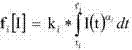
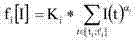
其中ki或者Ki、αi与(1)中的参数k和α相应。在方程式(2')中参数K为大写,以便指出相对于方程式(1)和(2)的参数k不同的物理单位: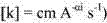


然而,不同于(2)、(2')的其它计算规则也是可能的。一般而言,计算规则包含对于至少两个耗损贡献形成如下形式的贡献: However, other calculation rules than (2), (2') are also possible. In general, calculation rules include contributions of at least two loss contributions of the form:

(其中i=l用于第一耗损贡献,而i=2用于第二耗损贡献,使得
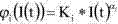
然后,耗损值能够计算为各耗损贡献di=fi[I]的总和,i=0..(N-1),例如以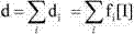
在用于耗损贡献计算规则fi的(2')中,仅在界限ti至t'i内进行求和。替代用于这些总和的硬界限,也能够在更大的时间段上求和,其中利用依赖于时间的函数

在图3中示出了函数


在图3b中示出了备选函数


函数

在方程式(4)的一般化中,耗损能够表示为总和,其中,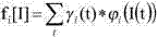

相应地,上述计算规则也能够应用于对时间上连续检测的电流值的积分。在该情况下,按照上述一般情况耗损能够表示成积分。该积分能够是数值上近似的。 Correspondingly, the calculation rules described above can also be applied to the integration of current values detected continuously over time. In this case, following the general case above, the loss can be expressed as the integral . This integral can be approximated numerically.
以下仍描述另外可能的变型方案。按照一变型方案,能够借助于共同的耗损贡献计算规则为多个具有类似耗损特征的电弧相位计算耗损贡献值。然而,不应该以同样的方式计算所有的电弧相位,也就是说,至少两个耗损贡献计算规则彼此有区别。 Still further possible variants are described below. According to a variant, the loss contribution values can be calculated for a plurality of arc phases with similar loss characteristics by means of a common loss contribution calculation rule. However, not all arc phases should be calculated in the same way, ie at least two loss contribution calculation rules differ from each other.
按照另一变型方案,除了电流I外电弧电压U也被检测并且在计算耗损值时被考虑。按照一实施方式,这些电压例如能够借助于附加的电压传感器被检测。然后相应耗损函数可具有例如以下形式: According to another variant, the arc voltage U is detected in addition to the current I and taken into account when calculating the loss value. According to one specific embodiment, these voltages can be detected, for example, by means of additional voltage sensors. The corresponding loss function may then have, for example, the following form:

表示与在开关操作期间流经开关的功率相关的变量的任意电气值一般能够被用于计算,即,例如电流I、电弧电压U、它们的乘积(如在上述方程式中)。 Arbitrary electrical values representing variables related to the power flowing through the switch during switching operation can generally be used for the calculations, ie eg current I, arc voltage U, their product (as in the above equation).
在另一实施方式中,在上述任一个方程式(例如(2)、(2')、(3)、(3'))中,功率也能够直接作为时间(而不是I(t))的函数被使用。 In another embodiment, in any of the above equations (eg (2), (2'), (3), (3')), the power It can also be used directly as a function of time (instead of I(t)).
按照另一变型方案,各个仅对耗损提供不明显贡献的电弧相位也能够被除去。例如在图1和2的例子中能够出于该原因除去扩散电弧相位(t0和t1之间的第零相位(Nullte Phase)),使得该计算对于相位i=l才开始。 According to another variant, individual arc phases which only make an insignificant contribution to losses can also be eliminated. For example, in the examples of FIGS. 1 and 2 , the spreading arc phase (the zeroth phase (Nullte Phase) between t0 and t1 ) can be omitted for this reason, so that the calculation only starts for phase i=1.
下文中描述适合实施在此描述的方法的开关控制装置和开关设备。该开关控制装置包括用于获取电流值(例如获取来自例如电流测量设备的所检测电流值,也来自用于模拟、内插等等的装置)的电流值输入模块,所述电流值作为时间的函数示出了在开关操作期间流经开关的接触电流。该开关控制装置进一步包括耗损确定模块,其具有计算单元和带有可通过计算单元执行的程序代码的数据存储器。该程序代码包括多个耗损贡献计算规则fi,它们被设置用于从所检测电流值的相应电流值子集
该程序代码尤其是包括用于实施在此描述的任一方法的指令。耗损贡献计算规则fi尤其是被设置用于从所检测的电流值的相应多个电流值子集

该开关设备是为高或中压而设计的,并且尤其是功率开关、例如真空功率开关(然而气体绝缘的功率开关也是可能的)。该开关设备包括上述开关控制装置。该接触电流尤其是电弧电流。该开关设备尤其是具有作为接触元件的TMF型接触件,因为它在此有特别明显的电弧相位。TMF型接触件特征在于,其构造在开关过程中或者在电弧中有利于主要的横向磁场。该横向磁场有利于电弧的运动并且由此导致明显的电弧相位。该接触件尤其是能够属于螺旋TMF型(如在图4中示出)。该接触元件由此能够包含带有圆的截面的平坦接触表面,例如带有螺旋形的间隙。备选地,该接触件也能够是形成为碗状的(碗状的,cup-shaped,类型)。该开关一般能够包含两个在纵向方向上相对彼此运动的接触件。 The switchgear is designed for high or medium voltages and is in particular a power switch, for example a vacuum power switch (gas-insulated power switches are also possible, however). The switchgear includes the above-mentioned switch control device. This touch current is in particular an arc current. In particular, the switching device has a TMF-type contact as the contact element, since it has a particularly pronounced arc phase here. The TMF-type contact is characterized in that its design favors the prevailing transverse magnetic field during the switching process or in the arc. This transverse magnetic field favors the movement of the arc and thus leads to a distinct arc phase. In particular, the contact piece can be of the helical TMF type (as shown in FIG. 4 ). The contact element can thus comprise a flat contact surface with a round cross-section, for example with a helical gap. Alternatively, the contact piece can also be formed in a bowl shape (cup-shaped type). The switch can generally comprise two contacts that move relative to each other in the longitudinal direction.
开关设备可含有多个接触元件(例如3个接触元件用于3个相)。在该情况下,其中每个接触元件的耗损能够如本文所述单独发生。 A switchgear may contain several contact elements (eg 3 contact elements for 3 phases). In this case, where the wear of each contact element can occur individually as described herein.
另外,该开关设备可包括诊断系统,其与开关控制装置相连,以便接收计算的耗损值。该诊断系统能够包含例如以下功能(每相位单独地): In addition, the switchgear can include a diagnostic system, which is connected to the switch control device in order to receive calculated wear values. The diagnostic system can include, for example, the following functions (individually per phase):
- 将耗损值相加成耗损总值,其对于多个开关过程作为总和表示接触件的总耗损; - add the loss values to a total loss value, which represents the total loss of the contact as a sum for several switching processes;
- 当耗损值或者耗损总值超出预给定的警报阈值或者警示阈值或者阻断阈值时,警报、警示或阻断指令的触发; - Triggering of an alarm, warning or blocking command when the loss value or the total loss value exceeds a predetermined alarm threshold or warning threshold or blocking threshold;
- 将按百分比的耗损计算成允许的最大耗损中目前耗损的份额(耗损值对比耗损总值); - Calculate the wear in percentage as the share of the current wear in the maximum allowable wear (loss value vs total loss value);
- 在耗损值或者耗损总值基础上计算估计的开关的剩余运行持续时间; - calculation of the estimated remaining operating duration of the switch on the basis of the wear value or total wear value;
- 将所确定耗损值或由此推导出的变量(例如耗损总值)转发到在线诊断服务器。 - Forwarding of the determined wear values or variables derived therefrom (eg total wear values) to the online diagnostic server.
以下仍列举本发明另外的一般方面。按照一方面,用于确定接触元件的耗损的方法包括从所检测到的电流值(I(t))中计算表示接触元件的耗损的耗损值(d),其中根据第一耗损贡献计算规则(fi)从至少一个用于第一时间间隔的电流值

在相应电流值内,一般不需要统一的耗损贡献计算规则。检测能够包括测量、尤其是在离散采样时间间隔中的采样测量,然而也能够包括(部分)模拟。该模拟能够基于一种模型,例如假定电流值处在正弦曲线上,或包含测量值之间的内插。以此方式电流值能够作为时间的连续函数或作为离散式检测的值的矢量供使用。 Within the corresponding current value, a uniform loss contribution calculation rule is generally not required. Detection can include measurements, especially sampled measurements in discrete sampling time intervals, but can also include (partial) simulations. The simulation can be based on a model, for example assuming that the current values lie on a sinusoid, or involving an interpolation between measured values. In this way the current value can be made available as a continuous function of time or as a vector of discretely detected values.
耗损贡献计算规则(作为函数)与零不同。作为函数与零相同的计算规则独立于值子集的电气值而根本不会得出耗损贡献(也就是说一直为零)。这种计算规则不视为耗损贡献计算规则。 The wear contribution calculation rule (as a function) is different from zero. The calculation rules identical to zero as a function result in no loss contribution at all (that is to say always zero) independently of the electrical values of the value subset. This calculation rule is not considered a wear and tear contribution calculation rule.
Claims (15)




Applications Claiming Priority (3)
| Application Number | Priority Date | Filing Date | Title |
|---|---|---|---|
| EP09177112A EP2328159B1 (en) | 2009-11-25 | 2009-11-25 | Method and device for determining the wear on a contact element |
| EP09177112.1 | 2009-11-25 | ||
| PCT/EP2010/066346 WO2011064064A1 (en) | 2009-11-25 | 2010-10-28 | Method and apparatus for determination of wear to a contact element |
Publications (2)
| Publication Number | Publication Date |
|---|---|
| CN102714101A true CN102714101A (en) | 2012-10-03 |
| CN102714101B CN102714101B (en) | 2015-04-08 |
Family
ID=42061006
Family Applications (1)
| Application Number | Title | Priority Date | Filing Date |
|---|---|---|---|
| CN201080062329.0A Active CN102714101B (en) | 2009-11-25 | 2010-10-28 | Method and apparatus for determination of wear to a contact element |
Country Status (8)
| Country | Link |
|---|---|
| US (1) | US9406451B2 (en) |
| EP (1) | EP2328159B1 (en) |
| CN (1) | CN102714101B (en) |
| AT (1) | ATE540415T1 (en) |
| BR (1) | BR112012012543B1 (en) |
| ES (1) | ES2380182T3 (en) |
| RU (1) | RU2551645C2 (en) |
| WO (1) | WO2011064064A1 (en) |
Cited By (3)
| Publication number | Priority date | Publication date | Assignee | Title |
|---|---|---|---|---|
| CN108226769A (en) * | 2016-12-21 | 2018-06-29 | 伊顿公司 | For the system and method in the contact service life of observation circuit cutout |
| CN113960458A (en) * | 2020-07-20 | 2022-01-21 | 施耐德电器工业公司 | Method for estimating characteristics of an electrical switching device and device for implementing said method |
| WO2022016595A1 (en) * | 2020-07-20 | 2022-01-27 | 西安热工研究院有限公司 | Method for inspecting electrical wear state of circuit breaker contact using arc power |
Families Citing this family (8)
| Publication number | Priority date | Publication date | Assignee | Title |
|---|---|---|---|---|
| DE102011080826B4 (en) * | 2011-08-11 | 2016-01-21 | Siemens Aktiengesellschaft | Method for determining the arc performance of a switch, method for triggering a switch based on the arc power and method for determining the load of the contacts of a switch based on the arc energy |
| CN107180728B (en) | 2016-03-11 | 2020-08-25 | Abb瑞士股份有限公司 | Solid-sealed pole and method of assembling the same |
| FR3060758B1 (en) * | 2016-12-16 | 2021-01-08 | Schneider Electric Ind Sas | METHOD AND DEVICE FOR DIAGNOSING THE WEAR OF AN ELECTRIC SWITCHING APPARATUS, AND ELECTRICAL APPARATUS INCLUDING SUCH A DEVICE |
| EP3460822B1 (en) * | 2017-09-26 | 2021-04-07 | ABB Schweiz AG | Method for operating a medium voltage circuit breaker or recloser and medium voltage circuit breaker or recloser itself |
| DE102020209645A1 (en) | 2020-07-30 | 2022-02-03 | Siemens Aktiengesellschaft | Method for determining the status of an electrical switchgear, monitoring unit for an electrical switchgear and electrical switchgear |
| CN114577452B (en) * | 2021-06-17 | 2024-02-23 | 正泰集团研发中心(上海)有限公司 | Life prediction methods, devices, electronic equipment and computer media for switch contacts |
| US11874314B2 (en) | 2022-02-09 | 2024-01-16 | Caterpillar Inc. | Electrical contact wear monitoring system |
| DE102022203697B3 (en) | 2022-04-12 | 2023-07-27 | Knick Elektronische Messgeräte GmbH & Co. KG | Monitoring device for highly dynamic currents, in particular for monitoring railway currents |
Citations (5)
| Publication number | Priority date | Publication date | Assignee | Title |
|---|---|---|---|---|
| CN1202979A (en) * | 1995-12-01 | 1998-12-23 | 西门子公司 | Method and device for monitoring consumption of contact elements in a switching device |
| EP1318533A1 (en) * | 2001-12-07 | 2003-06-11 | ABB Schweiz AG | Method for determining the state of contact wear in a circuit breaker |
| EP1475813A1 (en) * | 2003-05-07 | 2004-11-10 | ABB Technology AG | Method and apparatus for controlling switching devices in electrical switchgear |
| CN1618110A (en) * | 2001-12-21 | 2005-05-18 | 施耐德电器工业公司 | Method for determination of contact wear of switching devices |
| US20070222427A1 (en) * | 2004-05-13 | 2007-09-27 | Mitsubishi Electric Corporation | State Grasp Device, and Switching Control Device of Power Switching Apparatus Employing the State Grasp Device |
Family Cites Families (3)
| Publication number | Priority date | Publication date | Assignee | Title |
|---|---|---|---|---|
| SU1029250A1 (en) * | 1981-12-16 | 1983-07-15 | Ленинградское Электромашиностроительное Объединение "Электросила" Им.С.М.Кирова | Device for automatic measuring time of arcing on switching apparatus contacts |
| US6466023B2 (en) | 1998-12-28 | 2002-10-15 | General Electric Company | Method of determining contact wear in a trip unit |
| DE10345183B4 (en) * | 2003-09-29 | 2005-10-13 | Siemens Ag | Device for detecting contact erosion in switching devices |
-
2009
- 2009-11-25 AT AT09177112T patent/ATE540415T1/en active
- 2009-11-25 EP EP09177112A patent/EP2328159B1/en active Active
- 2009-11-25 ES ES09177112T patent/ES2380182T3/en active Active
-
2010
- 2010-10-28 BR BR112012012543-5A patent/BR112012012543B1/en active IP Right Grant
- 2010-10-28 CN CN201080062329.0A patent/CN102714101B/en active Active
- 2010-10-28 WO PCT/EP2010/066346 patent/WO2011064064A1/en not_active Ceased
- 2010-10-28 RU RU2012126118/07A patent/RU2551645C2/en active
-
2012
- 2012-05-25 US US13/480,927 patent/US9406451B2/en active Active
Patent Citations (5)
| Publication number | Priority date | Publication date | Assignee | Title |
|---|---|---|---|---|
| CN1202979A (en) * | 1995-12-01 | 1998-12-23 | 西门子公司 | Method and device for monitoring consumption of contact elements in a switching device |
| EP1318533A1 (en) * | 2001-12-07 | 2003-06-11 | ABB Schweiz AG | Method for determining the state of contact wear in a circuit breaker |
| CN1618110A (en) * | 2001-12-21 | 2005-05-18 | 施耐德电器工业公司 | Method for determination of contact wear of switching devices |
| EP1475813A1 (en) * | 2003-05-07 | 2004-11-10 | ABB Technology AG | Method and apparatus for controlling switching devices in electrical switchgear |
| US20070222427A1 (en) * | 2004-05-13 | 2007-09-27 | Mitsubishi Electric Corporation | State Grasp Device, and Switching Control Device of Power Switching Apparatus Employing the State Grasp Device |
Cited By (3)
| Publication number | Priority date | Publication date | Assignee | Title |
|---|---|---|---|---|
| CN108226769A (en) * | 2016-12-21 | 2018-06-29 | 伊顿公司 | For the system and method in the contact service life of observation circuit cutout |
| CN113960458A (en) * | 2020-07-20 | 2022-01-21 | 施耐德电器工业公司 | Method for estimating characteristics of an electrical switching device and device for implementing said method |
| WO2022016595A1 (en) * | 2020-07-20 | 2022-01-27 | 西安热工研究院有限公司 | Method for inspecting electrical wear state of circuit breaker contact using arc power |
Also Published As
| Publication number | Publication date |
|---|---|
| ES2380182T3 (en) | 2012-05-09 |
| EP2328159A1 (en) | 2011-06-01 |
| ATE540415T1 (en) | 2012-01-15 |
| WO2011064064A1 (en) | 2011-06-03 |
| BR112012012543A2 (en) | 2020-08-11 |
| RU2012126118A (en) | 2013-12-27 |
| US9406451B2 (en) | 2016-08-02 |
| CN102714101B (en) | 2015-04-08 |
| EP2328159B1 (en) | 2012-01-04 |
| BR112012012543B1 (en) | 2021-01-12 |
| US20120253695A1 (en) | 2012-10-04 |
| RU2551645C2 (en) | 2015-05-27 |
Similar Documents
| Publication | Publication Date | Title |
|---|---|---|
| CN102714101B (en) | Method and apparatus for determination of wear to a contact element | |
| US8095326B2 (en) | Method and device to predict a state of a power system in the time domain | |
| US20090308734A1 (en) | Apparatus and Method for Wafer Level Arc Detection | |
| US7123461B2 (en) | Method and device for monitoring switchgear in electrical switchgear assemblies | |
| CA2527086A1 (en) | Method and device for the detection of fault current arcing in electric circuits | |
| CN104956557A (en) | Determination of a leakage rate of an insulation gas | |
| CN117034760B (en) | Gas-insulated combined equipment state prediction model construction method and state prediction method | |
| CN101221218A (en) | Measurement of analog coil voltage and coil current | |
| Cui et al. | Electrical lifespan prediction of HVDC relay based on the accumulated arc erosion mass | |
| CN109470131A (en) | The detection method of thickness under vacuum state | |
| JP5844015B1 (en) | Power switching control device | |
| JP2008529227A (en) | Method and apparatus for determining the closing time of an electrical switchgear | |
| WO2018037114A1 (en) | Monitoring a transformer comprising a tap changer | |
| JP5031051B2 (en) | Circuit breaker monitoring device and detection method of circuit breaker monitoring device | |
| Ortbandt et al. | Parameter estimation in electrical power systems using Prony's method | |
| CN115128442A (en) | Dynamic evaluation method for electrical life of circuit breaker based on full-life operation information | |
| CN111952089A (en) | Systems and methods for controlled switches for circuit breakers and circuit breakers | |
| JP7649730B2 (en) | Anomaly detection device, anomaly detection system, and anomaly detection method | |
| Obarčanin et al. | Parameters for condition assessment of the high voltage circuit breakers arcing contacts using Dynamic Resistance measurement | |
| Runge et al. | A novel approach for Maximum plasma pressure estimation at surge current based on experimental investigations | |
| CN119106648B (en) | Boundary condition setting method for enhancing initial stability of simulation and related device | |
| JP7642931B1 (en) | Monitoring of transformers with tap changers | |
| Fnineche et al. | Current communication in high voltage switchgear contacts under high currents | |
| CN120072561B (en) | Breaking method of vacuum circuit breaker for new energy occasion | |
| KR102922665B1 (en) | Apparatus for arc detection and control method of the apparatus |
Legal Events
| Date | Code | Title | Description |
|---|---|---|---|
| C06 | Publication | ||
| PB01 | Publication | ||
| C10 | Entry into substantive examination | ||
| SE01 | Entry into force of request for substantive examination | ||
| C14 | Grant of patent or utility model | ||
| GR01 | Patent grant | ||
| TR01 | Transfer of patent right |
Effective date of registration: 20191129 Address after: Baden, Switzerland Patentee after: ABB Switzerland Co., Ltd. Address before: Zurich Patentee before: ABB Research Co., Ltd. |
|
| TR01 | Transfer of patent right |