CN102717896A - Deflating tester of brake system of airplane - Google Patents
Deflating tester of brake system of airplane Download PDFInfo
- Publication number
- CN102717896A CN102717896A CN2012100824303A CN201210082430A CN102717896A CN 102717896 A CN102717896 A CN 102717896A CN 2012100824303 A CN2012100824303 A CN 2012100824303A CN 201210082430 A CN201210082430 A CN 201210082430A CN 102717896 A CN102717896 A CN 102717896A
- Authority
- CN
- China
- Prior art keywords
- venting
- brake system
- experimental set
- airplane
- oil
- Prior art date
- Legal status (The legal status is an assumption and is not a legal conclusion. Google has not performed a legal analysis and makes no representation as to the accuracy of the status listed.)
- Granted
Links
Images

Landscapes
- Valves And Accessory Devices For Braking Systems (AREA)
Abstract
Description
技术领域 technical field
本发明总的涉及飞机刹车系统设备,尤其涉及用于飞机刹车系统的放气试验装置。The present invention generally relates to aircraft brake system equipment, in particular to a deflation test device for the aircraft brake system.
背景技术 Background technique
飞机起落架的刹车系统是保证飞机安全的重要系统,一旦刹车系统中存在过多的气体,必将会对飞机的安全产生重大的不良影响,刹车系统的放气试验装置就是用于保证飞机刹车系统内的多余气体顺利排出,从而保证飞机刹车系统的安全性。The brake system of the aircraft landing gear is an important system to ensure the safety of the aircraft. Once there is too much gas in the brake system, it will have a major adverse effect on the safety of the aircraft. The deflation test device of the brake system is used to ensure that the aircraft brakes The excess gas in the system is discharged smoothly, thus ensuring the safety of the aircraft braking system.
然而,飞机上的刹车系统的清洗工作一直以来都是飞机功能试验工作中的一个工艺难点,这主要是由于刹车系统的原理复杂,并且牵涉的成品件很多,此外,刹车系统的液压管路不同于其他液压管路:常规刹车系统只有一路压力管路而没有回油管路,不能构成一套完整的回路,使得液压油不能在刹车管路中循环。这给刹车系统的清洗、放气试验带来很多不便。However, the cleaning of the brake system on the aircraft has always been a technical difficulty in the functional test of the aircraft. This is mainly because the principle of the brake system is complex and involves many finished parts. In addition, the hydraulic pipelines of the brake system are different. For other hydraulic pipelines: the conventional brake system has only one pressure pipeline and no oil return pipeline, which cannot form a complete circuit, so that the hydraulic oil cannot circulate in the brake pipeline. This brings a lot of inconvenience to the cleaning and deflation test of the brake system.
随着飞机维修性需求以及节能环保意识的不断提高,亟需一种刹车放气试验装置,将刹车系统形成循环油路,以保证飞机刹车系统中的多余气体彻底排清。With the continuous improvement of aircraft maintainability requirements and awareness of energy saving and environmental protection, a brake deflation test device is urgently needed to form a circulating oil circuit in the brake system to ensure that the excess gas in the aircraft brake system is completely discharged.
发明内容 Contents of the invention
本发明的目的在于解决上述现有技术中的问题,提出一种新型的飞机刹车系统的放气试验装置,采用该放气试验装置可使得刹车系统中形成油路循环,并能够确保彻底排清飞机刹车系统中的多余气体。The object of the present invention is to solve the above-mentioned problems in the prior art, and propose a new type of air deflation test device for the aircraft brake system. The use of the air deflation test device can make the brake system form an oil circuit circulation, and can ensure that the air is completely discharged. Excess gas in aircraft braking system.
为此目的,本发明的飞机刹车系统的放气试验装置可包括油箱组件、排气管路以及油压测试装置,所述排气管路将油箱组件与飞机机轮的排气阀连通并形成油路循环,所述放气试验装置还设有流量指示器,其与所述排气管路连通。For this purpose, the deflation test device of the aircraft braking system of the present invention may include a fuel tank assembly, an exhaust pipeline and an oil pressure testing device, and the exhaust pipeline communicates the fuel tank assembly with the exhaust valve of the aircraft wheel and forms a The oil circuit circulates, and the said deflation test device is also provided with a flow indicator, which communicates with the exhaust pipeline.
根据本发明的一种实施方式,所述放气试验装置设置有四组排气管路,分别对应于飞机机轮的四路刹车管路,每组排气管路包括使液压油从所述油箱组件流至所述刹车管路的第一排气管路以及使液压油从所述刹车管路流至所述油箱组件的第二排气管路。进一步地,所述放气试验装置设置有四组油压测试装置,分别对应于所述四组排气管路,其中每组油压测试装置包括高压仪表、低压仪表以及相应的阀。According to an embodiment of the present invention, the deflation test device is provided with four groups of exhaust pipelines, respectively corresponding to the four brake pipelines of aircraft wheels, and each group of exhaust pipelines includes hydraulic oil from the A first exhaust line from the oil tank assembly to the brake line and a second exhaust line for hydraulic fluid to flow from the brake line to the oil tank assembly. Further, the deflation test device is provided with four sets of oil pressure test devices corresponding to the four sets of exhaust pipelines, wherein each set of oil pressure test devices includes a high pressure gauge, a low pressure gauge and a corresponding valve.
有利地,在所述第一排气管路与所述刹车管路之间可设有油滤。Advantageously, an oil filter may be provided between the first exhaust pipeline and the brake pipeline.
进一步地,所述油压测试装置检测并显示所述放气试验装置内的实际油压,与飞机刹车系统的显示油压相比较,以验证飞机油压是否准确正常。Further, the oil pressure test device detects and displays the actual oil pressure in the deflation test device, and compares it with the displayed oil pressure of the aircraft braking system to verify whether the aircraft oil pressure is accurate and normal.
可选地,所述流量指示器为由透明材料制成的管路,用以动态监控气体的排放情况。Optionally, the flow indicator is a pipeline made of transparent material for dynamic monitoring of gas discharge.
根据一种可选实施方式,所述放气试验装置被设置为可移动的刹车放气车,从而便于储存和取用。According to an optional embodiment, the deflation test device is configured as a movable brake deflation vehicle, so as to facilitate storage and retrieval.
不难理解,采用此技术方案进行放气试验时,在刹车系统中形成的油路循环有利于刹车系统内部的自清洁;流量指示器的设置更有利于实时观测系统排气状态,从而快速便捷地完成刹车管路中的气体排除;该放气试验装置结构简单、实施便利,可广泛适用于各种飞机刹车系统的放气,例如ARJ21-700飞机的刹车系统。It is not difficult to understand that when using this technical solution for the deflation test, the oil circuit formed in the brake system is conducive to self-cleaning inside the brake system; the setting of the flow indicator is more conducive to real-time observation of the exhaust state of the system, which is fast and convenient Completely remove the gas in the brake pipeline; the deflation test device has a simple structure and is convenient to implement, and can be widely used in the deflation of various aircraft brake systems, such as the brake system of ARJ21-700 aircraft.
附图说明 Description of drawings
本发明的更多特征及优点将通过下面结合附图对具体实施方式的进一步详细说明来更好地理解。其中:More features and advantages of the present invention will be better understood through the further detailed description of specific embodiments in conjunction with the accompanying drawings. in:
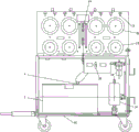
图1为根据本发明优选实施方式的刹车放气系统的放气试验装置的示意图;Fig. 1 is the schematic diagram of the deflation test device of the brake deflation system according to the preferred embodiment of the present invention;
图2为图1所示放气试验装置的液压系统的示意图。Fig. 2 is a schematic diagram of the hydraulic system of the deflation test device shown in Fig. 1 .
具体实施方式 Detailed ways
下面详细讨论具体实施方式的实施和使用。然而,应当理解,所讨论的具体实施方式仅仅示范性地说明实施和使用本发明的特定方式,而非限制本发明的范围。The making and using of specific embodiments are discussed in detail below. It should be understood, however, that the specific embodiments discussed are merely illustrative of specific ways to make and use the invention and do not limit the scope of the invention.
图1示出的根据本发明优选实施方式的刹车放气系统的放气试验装置被示意性地构造为刹车放气车的形式,在存放车40上主要设置有油箱组件2、油压测试装置22、23,管路(在图2中更为清楚地示出)通过接头4连接至油箱组件2并利用相应的控制装置,例如泵34实现液压油的泵送循环,其中,三通阀28将相应管路根据使用需要构造成使液压油从油箱组件2流至飞机机轮的刹车管路的第一排气管路以及使液压油从所述刹车管路流至油箱组件2的第二排气管路。结合图1和图2可看出,在液压油从油箱组件2流至刹车管路的排气管路上可设置有油滤30,用以确保进行再循环的液压油清洁度达到NAS16385级。The deflation test device of the brake deflation system shown in Fig. 1 according to the preferred embodiment of the present invention is schematically constructed as the form of a brake deflation car, and the storage car 40 is mainly provided with a fuel tank assembly 2, an oil
图中例示了分别对应于四组排气管路的四组油压测试装置22、23,其中,每组油压测试装置包括高压仪表23、低压仪表22以及相应的阀,例如图示的阀21和节流阀43。高压仪表23例如可显示5000psi范围内的压力值,低压仪表22则例如可显示500psi范围内能的压力值。可以理解的是,设置该油压测试装置的目的在于检测并显示放气试验装置内的实际油压,从而可与飞机刹车系统的显示油压相比较,以进一步验证飞机油压是否准确正常,这对于飞机刹车系统的保养维修也是不无裨益的。The figure illustrates four sets of oil
在本发明的放气试验装置中,还设置有流量指示器,在图1和图2中以标记64表示。该流量指示器64与排气管路连通,并由透明材料制成,例如玻璃。这样,混合有气体的液压油将是可视的,当指示器中没有气泡显示时,就表示刹车管路中的气体已排清,可以结束放气试验。In the outgassing test device of the present invention, a flow indicator is also provided, which is indicated by a
下面将概括描述利用本发明的放气试验装置,即刹车放气车进行刹车管路排气的过程。应当注意的是,飞机刹车系统的操作原理对于本领域技术人员来说已是相对熟知的,这里只侧重描述刹车放气车的操作方式。The process of using the deflation test device of the present invention, that is, the brake deflation vehicle to perform brake pipeline exhaust will be generally described below. It should be noted that the operating principle of the aircraft braking system is relatively well known to those skilled in the art, and here only focuses on describing the operation mode of the brake deflation vehicle.
首先,将刹车放气车的排气管路连接在飞机机轮的排气阀上,利用泵对液压油进行泵送并形成液压循环系统,检查液压循环系统中的各管路和附件应无泄露。对于长期没有使用的刹车放气车,还应使液压油自循环30分钟。First, connect the exhaust pipeline of the brake deflation vehicle to the exhaust valve of the aircraft wheel, use the pump to pump the hydraulic oil and form a hydraulic circulation system, and check that the pipelines and accessories in the hydraulic circulation system are free from damage. Give way. For brake deflation vehicles that have not been used for a long time, the hydraulic oil should also be self-circulating for 30 minutes.
然后,通过电控或手动将机轮的液压保险装置保持在常开状态,采用这种设置,由于液压保险装置在试验期间始终保持常开状态,用于刹车的液压油能够正常进入飞机刹车系统中,保障放气试验顺利进行,提高了系统的维修性。此时,试验人员踩下驾驶舱内的脚蹬并保持,以模拟刹车并产生油压促进液压循环系统中的液压油进行排气;缓慢打开机轮的排气阀,液压油通过排气管路流入刹车放气车的油箱中,观察与排气管路连通的流量指示器,无气泡时表示排气结束。Then, the hydraulic safety device of the wheel is kept in the normally open state by electronic control or manually. With this setting, since the hydraulic safety device is always kept in the normally open state during the test, the hydraulic oil used for braking can normally enter the aircraft brake system In the process, the smooth progress of the deflation test is ensured, and the maintainability of the system is improved. At this time, the testers stepped on the pedals in the cockpit and held them to simulate the brakes and generate oil pressure to promote the exhaust of the hydraulic oil in the hydraulic circulation system; slowly open the exhaust valve of the wheel, and the hydraulic oil passes through the exhaust pipe The air flows into the oil tank of the brake deflation vehicle, and observe the flow indicator connected to the exhaust pipe. When there is no air bubble, it means that the exhaust is over.
排气结束后可关闭机轮的排气阀,并恢复液压保险装置为关闭状态,松开脚蹬,卸下刹车放气车的排气管路,关闭泵,结束放气试验。After the exhaust is completed, close the exhaust valve of the wheel, and restore the hydraulic safety device to the closed state, release the pedal, remove the exhaust pipeline of the brake deflation vehicle, close the pump, and end the deflation test.
可以意识到的是,飞机的刹车管路通常存在有四路,分别对应左内轮、右内轮、左外轮和右外轮,四路管路的工作原理基本相同,因而可参照上述过程对各个机轮进行排气和检查。It can be realized that there are usually four brake pipelines in aircraft, corresponding to the left inner wheel, right inner wheel, left outer wheel and right outer wheel respectively. The working principle of the four pipelines is basically the same, so you can refer to the above process The wheels are vented and inspected.
此外,放气试验结束后油箱内的液压油可以过滤后留待下次试验,也可回收废弃。由于构成了油路循环,不会污染机轮部件。In addition, after the deflation test, the hydraulic oil in the oil tank can be filtered and left for the next test, or it can be recycled and discarded. Due to the formation of oil circuit circulation, the wheel parts will not be polluted.
本发明的技术内容及技术特点已揭示如上,应当理解的是,上述实施方式存在许多修改方式,这些方式对相关领域技术人员来说是很明显的。这些修改/变型落入本发明的相关领域中,也应当包括在所附的权利要求的范围中。The technical content and technical features of the present invention have been disclosed above, and it should be understood that there are many modifications to the above embodiments, which are obvious to those skilled in the relevant art. These modifications/variations fall within the relevant field of the present invention and should also be included in the scope of the appended claims.
Claims (7)
Priority Applications (1)
| Application Number | Priority Date | Filing Date | Title |
|---|---|---|---|
| CN201210082430.3A CN102717896B (en) | 2012-03-26 | 2012-03-26 | Deflating tester of brake system of airplane |
Applications Claiming Priority (1)
| Application Number | Priority Date | Filing Date | Title |
|---|---|---|---|
| CN201210082430.3A CN102717896B (en) | 2012-03-26 | 2012-03-26 | Deflating tester of brake system of airplane |
Publications (2)
| Publication Number | Publication Date |
|---|---|
| CN102717896A true CN102717896A (en) | 2012-10-10 |
| CN102717896B CN102717896B (en) | 2015-05-13 |
Family
ID=46943813
Family Applications (1)
| Application Number | Title | Priority Date | Filing Date |
|---|---|---|---|
| CN201210082430.3A Active CN102717896B (en) | 2012-03-26 | 2012-03-26 | Deflating tester of brake system of airplane |
Country Status (1)
| Country | Link |
|---|---|
| CN (1) | CN102717896B (en) |
Cited By (2)
| Publication number | Priority date | Publication date | Assignee | Title |
|---|---|---|---|---|
| CN109911833A (en) * | 2018-11-12 | 2019-06-21 | 中航通飞研究院有限公司 | A kind of passive brake system method for exhausting of aircraft |
| CN117585191A (en) * | 2023-10-25 | 2024-02-23 | 陕西飞机工业有限责任公司 | A brake exhaust integrated device and exhaust test method |
Families Citing this family (2)
| Publication number | Priority date | Publication date | Assignee | Title |
|---|---|---|---|---|
| RU2727450C1 (en) * | 2019-11-13 | 2020-07-21 | Федеральное государственное казенное военное образовательное учреждение высшего образования "Военный учебно-научный центр Военно-воздушных сил "Военно-воздушная академия имени профессора Н.Е. Жуковского и Ю.А. Гагарина" (г. Воронеж) | Mobile aerodrome-technical support system of aircrafts flight |
| RU2727769C1 (en) * | 2019-11-13 | 2020-07-23 | Федеральное государственное казенное военное образовательное учреждение высшего образования "Военный учебно-научный центр Военно-воздушных сил "Военно-воздушная академия имени профессора Н.Е. Жуковского и Ю.А. Гагарина" (г. Воронеж) | Small-sized mobile testing station of hydraulic systems of aircrafts |
Citations (5)
| Publication number | Priority date | Publication date | Assignee | Title |
|---|---|---|---|---|
| JPS6271752A (en) * | 1985-09-24 | 1987-04-02 | Sumitomo Heavy Ind Ltd | Method for venting air from brake oil in hydraulic brake operating circuit |
| DE3935353A1 (en) * | 1989-10-24 | 1991-04-25 | Teves Gmbh Alfred | Hydraulic braking system ventilation for antilock pressure control - involves valve adjacent to wheel brake cylinder remaining open to atmos. until fluid emerges without bubbling |
| JPH04121264A (en) * | 1990-09-10 | 1992-04-22 | Fuji Heavy Ind Ltd | Method for purging air from hydraulic brake device for vehicle |
| US20040251740A1 (en) * | 2001-08-03 | 2004-12-16 | Guenther Schmidt | Method used for bleeding a hydraulic vehicle brake system |
| CN202038460U (en) * | 2011-04-11 | 2011-11-16 | 新乡平原航空技术工程有限公司 | Hydraulic oil test truck for hydraulic system of airplanes |
-
2012
- 2012-03-26 CN CN201210082430.3A patent/CN102717896B/en active Active
Patent Citations (5)
| Publication number | Priority date | Publication date | Assignee | Title |
|---|---|---|---|---|
| JPS6271752A (en) * | 1985-09-24 | 1987-04-02 | Sumitomo Heavy Ind Ltd | Method for venting air from brake oil in hydraulic brake operating circuit |
| DE3935353A1 (en) * | 1989-10-24 | 1991-04-25 | Teves Gmbh Alfred | Hydraulic braking system ventilation for antilock pressure control - involves valve adjacent to wheel brake cylinder remaining open to atmos. until fluid emerges without bubbling |
| JPH04121264A (en) * | 1990-09-10 | 1992-04-22 | Fuji Heavy Ind Ltd | Method for purging air from hydraulic brake device for vehicle |
| US20040251740A1 (en) * | 2001-08-03 | 2004-12-16 | Guenther Schmidt | Method used for bleeding a hydraulic vehicle brake system |
| CN202038460U (en) * | 2011-04-11 | 2011-11-16 | 新乡平原航空技术工程有限公司 | Hydraulic oil test truck for hydraulic system of airplanes |
Cited By (3)
| Publication number | Priority date | Publication date | Assignee | Title |
|---|---|---|---|---|
| CN109911833A (en) * | 2018-11-12 | 2019-06-21 | 中航通飞研究院有限公司 | A kind of passive brake system method for exhausting of aircraft |
| CN109911833B (en) * | 2018-11-12 | 2022-12-13 | 中航通飞研究院有限公司 | Exhaust method of passive brake system of airplane |
| CN117585191A (en) * | 2023-10-25 | 2024-02-23 | 陕西飞机工业有限责任公司 | A brake exhaust integrated device and exhaust test method |
Also Published As
| Publication number | Publication date |
|---|---|
| CN102717896B (en) | 2015-05-13 |
Similar Documents
| Publication | Publication Date | Title |
|---|---|---|
| CN108128299A (en) | A kind of online inflation of air brakes vehicles and detecting system and method | |
| CN102717896B (en) | Deflating tester of brake system of airplane | |
| DE102012221770B4 (en) | Test method for a brake system | |
| CN101813564B (en) | Automation testing platform control air circuit system of subway brake unit | |
| CN202110045U (en) | Seal detection device | |
| WO2008055623A1 (en) | Leakage test in an air conditioner | |
| CN104180147B (en) | The method of work of automatic gear-box oil changing device | |
| CN105938054B (en) | Motorcycle ABS durability test experimental bench | |
| CN205445991U (en) | Air compressor machine exhaust oil content detection device | |
| CN103604572A (en) | Leakage detection method for central air conditioner copper tube | |
| CN108591140A (en) | The load test stand of aviation hydraulic oil pump vehicle | |
| CN107063717A (en) | A kind of device for detecting performance of fork truck energy storing brake system | |
| CN204269384U (en) | A kind of ABS performance testing device | |
| CN211147920U (en) | Static brake pressure test system of semitrailer | |
| CN212159074U (en) | Urban rail vehicle air spring pressure simulation tool | |
| CN108120588A (en) | The fatigue endurance test method of air-brake coupling hose | |
| DE102010016983A1 (en) | Brake assembly malfunction recognition method for vehicle, involves comparing temperatures at parts of assembly and/or temperature gradients of vehicle sides, and recognizing malfunction when determined deviation is above threshold value | |
| CN102229338B (en) | Pressure monitoring system for commercial automobile braking piping and calibrating method | |
| CN106427973B (en) | Screening method for relay valve of CRH380 series motor train unit | |
| CN203732221U (en) | Water tank pressure test device for trains | |
| CN205808645U (en) | A kind of air brake piping tightness test system | |
| CN207728648U (en) | A kind of integrated hydraulic power unit of high pressure high cleanliness two | |
| CN203365126U (en) | An empty-vehicle safety valve test apparatus | |
| CN205861353U (en) | Motorcycle ABS durability test laboratory table | |
| CN202793926U (en) | Static state rigidity testing device of parking braking assembly pull rod body |
Legal Events
| Date | Code | Title | Description |
|---|---|---|---|
| C06 | Publication | ||
| PB01 | Publication | ||
| C10 | Entry into substantive examination | ||
| SE01 | Entry into force of request for substantive examination | ||
| C14 | Grant of patent or utility model | ||
| GR01 | Patent grant |