CN102724092A - Profibus-DP communication protocol redundancy master station - Google Patents
Profibus-DP communication protocol redundancy master station Download PDFInfo
- Publication number
- CN102724092A CN102724092A CN2012102106302A CN201210210630A CN102724092A CN 102724092 A CN102724092 A CN 102724092A CN 2012102106302 A CN2012102106302 A CN 2012102106302A CN 201210210630 A CN201210210630 A CN 201210210630A CN 102724092 A CN102724092 A CN 102724092A
- Authority
- CN
- China
- Prior art keywords
- card
- master station
- signal
- communication
- standby
- Prior art date
- Legal status (The legal status is an assumption and is not a legal conclusion. Google has not performed a legal analysis and makes no representation as to the accuracy of the status listed.)
- Pending
Links
- 238000004891 communication Methods 0.000 title claims abstract description 131
- 230000001360 synchronised effect Effects 0.000 claims description 35
- 238000000034 method Methods 0.000 claims description 9
- 230000005540 biological transmission Effects 0.000 claims description 4
- 230000008569 process Effects 0.000 claims description 4
- 238000006243 chemical reaction Methods 0.000 claims description 3
- 230000000630 rising effect Effects 0.000 claims description 3
- 238000012545 processing Methods 0.000 abstract description 5
- 238000010586 diagram Methods 0.000 description 7
- 238000013461 design Methods 0.000 description 4
- 230000006870 function Effects 0.000 description 4
- 238000001514 detection method Methods 0.000 description 2
- 238000005516 engineering process Methods 0.000 description 2
- 230000009286 beneficial effect Effects 0.000 description 1
- 230000008901 benefit Effects 0.000 description 1
- 230000007547 defect Effects 0.000 description 1
- 238000003745 diagnosis Methods 0.000 description 1
- 230000000694 effects Effects 0.000 description 1
- 230000006872 improvement Effects 0.000 description 1
- 238000002955 isolation Methods 0.000 description 1
- 230000007774 longterm Effects 0.000 description 1
- 238000004519 manufacturing process Methods 0.000 description 1
- 230000007246 mechanism Effects 0.000 description 1
- 230000000737 periodic effect Effects 0.000 description 1
- 238000011084 recovery Methods 0.000 description 1
- 238000011160 research Methods 0.000 description 1
- 230000004044 response Effects 0.000 description 1
- 230000009466 transformation Effects 0.000 description 1
- 238000012795 verification Methods 0.000 description 1
Images


Landscapes
- Hardware Redundancy (AREA)
- Computer And Data Communications (AREA)
Abstract
本发明公开了一种Profibus-DP现场总线通信协议冗余主站,包括主站通信卡和主站备用卡:主站通信卡处于工作状态,对下通过DP接口电路与从站交换数据,对上通过DPRAM接口电路与中央处理卡件交换数据;主站通信卡周期性向主站备用卡备份主站通信卡参数集合和从站的实时I/O数据;主站备用卡处于热备用等待状态,当主站通信卡无法工作时接替其进行工作,周期性接收主站通信卡发送的主站通信卡参数集合和从站的实时I/O数据。本发明不要求工作主站与备用主站同时工作,可以连接冗余DP口从站,也可直接连接单DP口从站的冗余主站产品;克服了现有主站冗余方式所造成的主站产品选型局限性大、接入单DP口从站增加成本的缺陷。
The invention discloses a Profibus-DP field bus communication protocol redundant master station, which includes a master station communication card and a master station standby card: the master station communication card is in a working state, and the data is exchanged with the slave station through a DP interface circuit, and the Exchange data with the central processing card through the DPRAM interface circuit; the communication card of the master station periodically backs up the parameter set of the communication card of the master station and the real-time I/O data of the slave station to the backup card of the master station; the backup card of the master station is in a hot standby waiting state, When the master station communication card fails to work, take over its work, and periodically receive the master station communication card parameter set sent by the master station communication card and the real-time I/O data of the slave station. The invention does not require the working master station and the backup master station to work at the same time, can connect redundant DP port slave stations, and can also directly connect redundant master station products with single DP port slave stations; The limitations of the master station product selection are large, and the access to the single DP port slave station increases the cost.
Description
技术领域 technical field
本发明属于现场总线冗余技术领域,涉及一种Profibus-DP现场总线通信协议冗余主站及冗余模式。The invention belongs to the technical field of field bus redundancy, and relates to a Profibus-DP field bus communication protocol redundant master station and a redundant mode.
背景技术 Background technique
Profibus现场总线是一种具有广泛应用范围的、开放的、全数字、串行通信总线,在集中自动化系统向分散自动化系统转变方面是一种重大突破。Profibus通信协议中采用了信息冗余技术,如Profibus-DP物理层采用RS485差模、非归零NRZ、异步传输信号,数据链路层报文采用HD=4的海明距离、CRC码校验等。当前工业控制领域对控制系统的可靠性提出了更高要求,毫无疑问冗余技术就是实现高可靠性的一个途径。Profibus field bus is an open, all-digital, serial communication bus with a wide range of applications. It is a major breakthrough in the transformation from centralized automation system to decentralized automation system. The Profibus communication protocol adopts information redundancy technology. For example, the Profibus-DP physical layer adopts RS485 differential mode, non-return-to-zero NRZ, and asynchronous transmission signals, and the data link layer message adopts HD=4 Hamming distance and CRC code verification wait. The current industrial control field puts forward higher requirements on the reliability of the control system. There is no doubt that redundancy technology is a way to achieve high reliability.
在现场总线控制系统的全局概念下再讨论可靠性时,通信网络本身就成为了它的瓶颈。当站在控制系统的高度向下审视通信网络时会发现,网络通道上站节点、通信线路都是单一的,出现故障的几率增大。因此研究站节点与通信线路冗余的通信网络对于工业过程领域有着重大的现实意义。When discussing reliability under the overall concept of fieldbus control system, the communication network itself becomes its bottleneck. When looking down at the communication network from the height of the control system, you will find that the station nodes and communication lines on the network channel are single, and the probability of failure increases. Therefore, the communication network with redundant nodes and communication lines of the research station has great practical significance for the field of industrial process.
Profibus总线的站节点分为主站和从站两大类,而主站又分为一类主站和二类主站。由于二类主站是对一类主站和从站进行组态的计算机,对控制系统长期运行可靠性影响甚微,因此站节点冗余主要考虑一类主站和从站分别冗余。The station nodes of the Profibus bus are divided into two categories: the master station and the slave station, and the master station is divided into a first-class master station and a second-class master station. Since the second-class master station is a computer that configures the first-class master station and the slave station, it has little impact on the long-term operation reliability of the control system, so the station node redundancy mainly considers the redundancy of the first-class master station and the slave station respectively.
一类主站是DP通信网络的主角,它起着主动与从站交换数据并控制整个网络的作用。一旦一类主站出现故障则受其控制的所有从站将无法工作,该主站管理的DP网段通信将随之崩溃。因此一类主站冗余对于工业控制领域而言,是必须的要求。冗余配置的两块通信主站执行同样的应用程序,Profibus协议中对一类主站冗余模式和实现方式未做任何规定。A type of master station is the protagonist of the DP communication network, which plays the role of actively exchanging data with slave stations and controlling the entire network. Once a type of master station fails, all slave stations controlled by it will fail to work, and the DP network segment communication managed by the master station will collapse accordingly. Therefore, a type of master station redundancy is a necessary requirement for the industrial control field. The two communication master stations in redundant configuration execute the same application program, and the Profibus protocol does not make any regulations on the redundancy mode and implementation of a class of master stations.
当前工业控制市领域完全采用国外厂商的主站冗余方式,即工作主站和备用主站同时工作,互为冗余的两个通信主站都在主动和从站交换数据并控制整个网络。这种模式下工作主站与备用主站通过2根DP电缆分别与冗余从站的各自通信口或单个从站的冗余通信口直接连接。At present, the industrial control market fully adopts the master station redundancy method of foreign manufacturers, that is, the working master station and the standby master station work at the same time, and the two redundant communication master stations are actively exchanging data with the slave station and controlling the entire network. In this mode, the working master station and the standby master station are directly connected to the respective communication ports of the redundant slave station or the redundant communication port of a single slave station through 2 DP cables.
上述主站冗余方式,要求工作主站与备用主站必须同时与从站进行数据交换,对主站要求很高,产品选型局限性非常大;且该冗余方式中要接入单DP口从站,必须添加网络组件,增加了成本。The above master station redundancy method requires the working master station and the standby master station to exchange data with the slave station at the same time, which has high requirements on the master station and has great limitations in product selection; and in this redundancy method, a single DP must be connected. Port slave station must add network components, which increases the cost.
发明内容 Contents of the invention
本发明解决的问题在于提供一种Profibus-DP现场总线通信协议冗余主站,不要求工作主站与备用主站同时工作,既可以连接冗余从站,也可直接连接单口从站的冗余主站;克服了现有主站冗余方式所造成的主站产品选型局限性大、接入单DP口从站增加成本的缺陷。The problem solved by the present invention is to provide a redundant master station of the Profibus-DP field bus communication protocol, which does not require the working master station and the standby master station to work at the same time, and can be connected to the redundant slave station or directly connected to the redundant master station of the single-port slave station. Residual master station; overcome the shortcomings of the existing master station redundancy mode, such as the limitation of master station product selection and the increased cost of accessing a single DP port slave station.
本发明是通过以下技术方案来实现:The present invention is achieved through the following technical solutions:
一种Profibus-DP现场总线通信协议冗余主站,包括主站通信卡和主站备用卡:A Profibus-DP field bus communication protocol redundant master station, including master station communication card and master station standby card:
主站通信卡处于工作状态,对下通过DP接口电路与从站交换数据,对上通过DPRAM接口电路与中央处理卡件交换数据;主站通信卡周期性向主站备用卡备份主站通信卡参数集合和从站的实时I/O数据;The communication card of the master station is in the working state, and exchanges data with the slave station through the DP interface circuit, and exchanges data with the central processing card through the DPRAM interface circuit; the communication card of the master station periodically backs up the parameters of the communication card of the master station to the standby card of the master station Real-time I/O data of collections and slaves;
主站备用卡处于热备用等待状态,当主站通信卡无法工作时接替其进行工作,周期性接收主站通信卡发送的主站通信卡参数集合和从站的实时I/O数据;The standby card of the master station is in the hot standby waiting state. When the communication card of the master station fails to work, it takes over to work, and periodically receives the parameter set of the communication card of the master station sent by the communication card of the master station and the real-time I/O data of the slave station;
主站通信卡和主站备用卡上均设有主备冗余电路和微处理器;Both the main station communication card and the main station standby card are equipped with main and standby redundant circuits and microprocessors;
主备冗余电路包括主备冗余逻辑模块和同步通讯接口:主备冗余逻辑模块对主站通信卡和主站备用卡的主备角色做出判断;同步通讯接口为主站通信卡向主站备用卡的备份通道;The main-standby redundant circuit includes a main-standby redundant logic module and a synchronous communication interface: the main-standby redundant logic module judges the main-standby role of the main station communication card and the main station standby card; the synchronous communication interface communicates to the main station communication card The backup channel of the backup card of the main station;
主备冗余逻辑模块和同步通讯接口分别与微处理器相连接。The active and standby redundant logic modules and the synchronous communication interface are respectively connected with the microprocessor.
所述的主站通信卡通过底板插槽连接到通讯网络上,通过串形数据总线读取从站数据;The master station communication card is connected to the communication network through the backplane slot, and the slave station data is read through the serial data bus;
所述的串形数据总线为RS485总线。The serial data bus is RS485 bus.
所述的主站通信卡和主站备用卡上均设有以下模块:Both the master station communication card and the master station standby card are provided with the following modules:
存储器电路,包括分别与微处理器连接的Flash电路和内存电路SDRAM,Flash电路存储用户应用程序,SDRAM电路用于微处理器高速执行用户应用程序;The memory circuit includes a Flash circuit and a memory circuit SDRAM respectively connected to the microprocessor, the Flash circuit stores the user application program, and the SDRAM circuit is used for the microprocessor to execute the user application program at high speed;
微处理器,执行运算处理包括运行Profibus协议栈上的固化程序和运行存储器电路上的用户应用程序;Microprocessor, performing arithmetic processing including running the firmware program on the Profibus protocol stack and running the user application program on the memory circuit;
微处理器上设有复位电路。A reset circuit is provided on the microprocessor.
所述的电复位电路采用标准看门狗定时器:1.6s内WDI端没有收到来自MPU/MCU的触发信号,并且WDI处于非高阻态,则WDO输出变低电平,启动看门狗定时器。The electrical reset circuit uses a standard watchdog timer: if the WDI terminal does not receive a trigger signal from the MPU/MCU within 1.6s, and WDI is in a non-high-impedance state, then the WDO output becomes low, and the watchdog is started timer.
所述的主站通信卡和主站备用卡中任意一卡的输出信号通过底板插槽分别与另外一块卡的输入信号连接在一起;The output signal of any card in the master station communication card and the master station backup card is respectively connected with the input signal of another card through the backplane slot;
输出信号包括:本卡存在信号、本卡状态信号和本角色信号;并同步数据输出STXD,同步时钟输出SCLKOUT;The output signals include: the existence signal of the card, the status signal of the card and the role signal; and the synchronous data output STXD, and the synchronous clock output SCLKOUT;
输入信号包括:相对卡存在信号、相对卡状态信号、相对卡角色信号;并同步数据输入SRXD,同步时钟输入SCLKIN。Input signals include: relative card presence signal, relative card status signal, relative card role signal; and synchronous data input SRXD, synchronous clock input SCLKIN.
所述的主备冗余逻辑模块的设定包括:The setting of the active and standby redundant logical modules includes:
本卡存在否,0:存在,1:不存在;Whether the card exists, 0: exists, 1: does not exist;
本卡状态,0:正常,1:故障;Status of the card, 0: normal, 1: failure;
相对卡存在否,0:存在,1:不存在;Relative card exists or not, 0: exists, 1: does not exist;
相对卡状态,0:正常,1:故障;Relative card status, 0: normal, 1: failure;
相对卡角色,0:主卡,1:备卡;Relative card role, 0: main card, 1: backup card;
本卡角色,0:主卡,1:备卡;The role of this card, 0: main card, 1: standby card;
形成判定主备角色的三对条件:本卡存在信号OUT1与相对卡存在信号IN1;本卡状态信号OUT2与相对卡状态信号IN2;本卡角色信号OUT3与相对卡角色信号IN3。Form three pairs of conditions for judging the roles of master and backup: the presence signal OUT1 of the own card and the presence signal IN1 of the relative card; the state signal OUT2 of the own card and the state signal IN2 of the relative card; the role signal OUT3 of the own card and the role signal IN3 of the relative card.
所述的主备冗余逻辑模块对主站通信卡和主站备用卡的主备角色做出判断为:The master-standby redundancy logic module makes a judgment on the master-standby role of the master station communication card and the master station backup card as follows:
当本卡上电后,微处理器发出上升沿脉冲至D触发器时钟端,使D触发器输出Q=1,经过非门后获得输出本卡存在信号OUT1=0;当本卡上电且通过检测后,微处理器发出低电平,获得输出本卡正常信号OUT2=0;When the card is powered on, the microprocessor sends a rising edge pulse to the clock terminal of the D flip-flop, so that the D flip-flop outputs Q=1, and the output card existence signal OUT1=0 is obtained after passing through the NOT gate; when the card is powered on and After passing the detection, the microprocessor sends out a low level, and obtains the normal signal OUT2=0 of the output card;
相对卡上电后所判断出的存在否信号与正常否信号通过底板传至本卡IN1和IN2信号;The existence or non-existence signal and normal non-signal judged after the relative card is powered on are transmitted to the IN1 and IN2 signals of the card through the backplane;
依据以上两对存在否信号和正常否信号获得本卡与相对卡的角色判断;Based on the above two pairs of presence/absence signals and normal/no signals, the role judgment of this card and the corresponding card is obtained;
当主站通信卡发生故障时,主站通信卡微处理器无法工作即无法持续发出低电平,使得输出本卡故障信号OUT2=1,该信号通过底板传至相对卡IN2=1,经过非门后变为“0”,与D触发器输出端经过非门的信号“0”经过或运算,等到信号“0”,传送至逻辑“与”门的第2个管脚,“与”门输出信号“0”,使得输出相对角色为备卡的信号OUT3=0,由此实现了主备卡角色的转换。When the communication card of the master station fails, the microprocessor of the communication card of the master station cannot work, that is, it cannot continuously send out low level, so that the fault signal OUT2=1 of the card is output, and the signal is transmitted to the relative card IN2=1 through the backplane, and after a non-stop After the gate, it becomes "0", and the output of the D flip-flop passes through the signal "0" of the NOT gate through the OR operation, and waits until the signal "0" is sent to the second pin of the logical "AND" gate, the "AND" gate The output signal "0" makes the output signal OUT3=0 whose relative role is the standby card, thereby realizing the conversion of the roles of the active and standby cards.
所述的同步通讯接口电路包括同步数据输出STXD、同步时钟输出SCLKOUT、同步数据输入SRXD和同步时钟输入SCLKIN,该四种信号由3态门接入,3态门的使能端由本卡存在信号OUT1来控制。The synchronous communication interface circuit includes synchronous data output STXD, synchronous clock output SCLKOUT, synchronous data input SRXD and synchronous clock input SCLKIN. OUT1 to control.
所述的主站通信卡和主站备用卡通过DP电缆连接,再通过DP电缆与从站连接。The communication card of the master station is connected with the backup card of the master station through a DP cable, and then connected with the slave station through a DP cable.
与现有技术相比,本发明具有以下有益的技术效果:Compared with the prior art, the present invention has the following beneficial technical effects:
本发明提供的Profibus-DP现场总线通信协议冗余主站,不要求工作主站与备用主站同时工作,既可以连接冗余DP口从站,也可直接连接单DP口从站的冗余主站产品;主站通信卡处于工作状态,主站备用卡处于热备用等待状态,主站通信卡周期性向主站备用卡备份主站通信卡参数集合和从站的实时I/O数据;当主站通信卡无法工作时接替其进行工作;通过主备冗余逻辑模块和同步通讯电路进行数据的周期性同步备份,实现了工作主站和备用主站的无干扰切换以及主站与从站无故障数据通讯;克服了现有主站冗余方式所造成的主站产品选型局限性大、接入单DP口从站增加成本的缺陷。The Profibus-DP fieldbus communication protocol redundant master station provided by the present invention does not require the working master station and the standby master station to work at the same time, and can be connected to redundant DP port slave stations or directly connected to single DP port slave stations. Master station product; the communication card of the master station is in the working state, the backup card of the master station is in the hot standby waiting state, and the communication card of the master station periodically backs up the parameter set of the communication card of the master station and the real-time I/O data of the slave station to the backup card of the master station; When the communication card of the master station fails to work, it will take over its work; the periodic synchronous backup of data is carried out through the active and standby redundant logic modules and the synchronous communication circuit, which realizes the interference-free switching between the working master station and the standby master station, and the master station and the slave station Fault-free data communication; it overcomes the limitations of the main station product selection caused by the existing master station redundancy mode, and the defects of increasing the cost of connecting to the single DP port slave station.
当前工业控制市领域完全采用国外厂商的主站冗余方式,造成必须选购国外厂商的主站。以西门子冗余主站443-5为例,一套通信板价格为5万人民币,当需要接入单DP设备时,必须增加Y-Link组件,其价格为8仟人民币。而选用本发明一套冗余通信板价格为壹万人民币,经济效益非常显著。At present, the industrial control market completely adopts the redundancy mode of the master station of foreign manufacturers, which makes it necessary to purchase the master station of foreign manufacturers. Taking the Siemens redundant master station 443-5 as an example, the price of a set of communication board is 50,000 RMB. When a single DP device needs to be connected, a Y-Link component must be added, and the price is 8,000 RMB. And choose a set of redundant communication board price of the present invention to be 10,000 RMB, economic benefit is very remarkable.
附图说明 Description of drawings
图1是现有冗余模式图;Figure 1 is a diagram of an existing redundancy mode;
图2是本发明的冗余模式图。FIG. 2 is a diagram of a redundancy mode of the present invention.
图3是Profibus-DP通信协议冗余主站结构示意图;Fig. 3 is a structural schematic diagram of the Profibus-DP communication protocol redundant master station;
图4是Profibus-DP主站主备冗余逻辑图;Figure 4 is a logical diagram of the active and standby redundancy of the Profibus-DP master station;
图5是Profibus-DP主站主备同步通讯电路图;Figure 5 is a circuit diagram of the main-standby synchronous communication of the Profibus-DP master station;
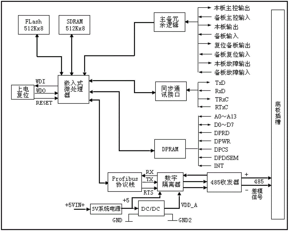
图6是Profibus-DP主站接口电路框图。Figure 6 is a block diagram of the interface circuit of the Profibus-DP master station.
具体实施方式 Detailed ways
本发明提供的Profibus-DP现场总线通信协议冗余主站,提出了一种新的冗余模式,不要求工作主站与备用主站同时工作,既可以连接冗余从站,也可直接连接单口从站的冗余主站。下面结合具体的实施例对本发明做进一步的详细说明,所述是对本发明的解释而不是限定。The Profibus-DP field bus communication protocol redundant master station provided by the present invention proposes a new redundant mode, which does not require the working master station and the standby master station to work at the same time, and can be connected to redundant slave stations or directly Redundant master for single-port slaves. The present invention will be further described in detail below in conjunction with specific embodiments, which are explanations of the present invention rather than limitations.
首先提出冗余模式的改进,参见图1与图2:Firstly, the improvement of the redundancy mode is proposed, see Figure 1 and Figure 2:
当前Profibus-DP冗余主站采用工作主站和备用主站同时工作机制,互为冗余的两个通信主站都在主动和从站交换数据并控制整个网络。这种模式下工作主站与备用主站通过2根DP电缆分别与冗余从站的各自通信口或单个从站的冗余通信口直接连接。The current Profibus-DP redundant master station adopts the working mechanism of the working master station and the standby master station at the same time, and the two redundant communication master stations are actively exchanging data with the slave station and controlling the entire network. In this mode, the working master station and the standby master station are directly connected to the respective communication ports of the redundant slave station or the redundant communication port of a single slave station through 2 DP cables.
改进的冗余模式为:不要求Profibus-DP冗余主站中工作主站和备用主站同时工作,只有工作主站在主动和从站交换数据并控制整个网络,周期性向备用主站备份主站参数集合以及从站的实时I/O数据;备用主站只是周期接收工作主站备份的数据。这种模式下工作主站与备用主站通过DP电缆连接在一起,再通过1根DP电缆与从站连接。The improved redundancy mode is: the working master station and the standby master station in the Profibus-DP redundant master station are not required to work at the same time, only the working master station actively exchanges data with the slave station and controls the entire network, and periodically backs up the master station to the standby master station The set of station parameters and the real-time I/O data of the slave station; the standby master station only periodically receives the data backed up by the working master station. In this mode, the working master station and the standby master station are connected together through a DP cable, and then connected to the slave station through a DP cable.
基于上述冗余模式的Profibus-DP现场总线通信协议冗余主站,采用1:1冗余,包括主站通信卡(工作主站)和主站备用卡(备用主站),将其通过DP电缆连接在一起,再通过1根DP电缆与从站连接;The Profibus-DP fieldbus communication protocol redundant master station based on the above redundancy mode adopts 1:1 redundancy, including the master station communication card (working master station) and the master station backup card (standby master station), which are passed through DP The cables are connected together, and then connected to the slave station through a DP cable;
主站通信卡处于工作状态,对下通过DP接口电路与从站交换数据,对上通过DPRAM接口电路与中央处理卡件交换数据;主站通信卡周期性向主站备用卡备份主站通信卡参数集合和从站的实时I/O数据;The communication card of the master station is in the working state, and exchanges data with the slave station through the DP interface circuit, and exchanges data with the central processing card through the DPRAM interface circuit; the communication card of the master station periodically backs up the parameters of the communication card of the master station to the standby card of the master station Real-time I/O data of collections and slaves;
主站备用卡处于热备用等待状态,当主站通信卡无法工作时接替其进行工作,周期性接收主站通信卡发送的主站通信卡参数集合和从站的实时I/O数据;The standby card of the master station is in the hot standby waiting state. When the communication card of the master station fails to work, it takes over to work, and periodically receives the parameter set of the communication card of the master station sent by the communication card of the master station and the real-time I/O data of the slave station;
主站通信卡和主站备用卡上均设有主备冗余电路和微处理器;Both the main station communication card and the main station standby card are equipped with main and standby redundant circuits and microprocessors;
主备冗余电路包括主备冗余逻辑模块和同步通讯接口:主备冗余逻辑模块对主站通信卡和主站备用卡角色做出判断;同步通讯接口为主站通信卡向主站备用卡的备份通道;The main-standby redundant circuit includes a main-standby redundant logic module and a synchronous communication interface: the main-standby redundant logic module judges the roles of the main station communication card and the main station standby card; Card backup channel;
主备冗余逻辑模块和同步通讯接口分别与微处理器相连接。The active and standby redundant logic modules and the synchronous communication interface are respectively connected with the microprocessor.
主站通信卡和主站备用卡采用相同的结构,下面以主站通信卡为例对其结构进行具体说明:The main station communication card and the main station standby card adopt the same structure. The following takes the main station communication card as an example to describe its structure:
参见图3,Profibus-DP冗余主站的主站通信卡主要由微处理器(嵌入式)、存储器电路、复位电路、主备冗余电路和接口电路组成。Referring to Figure 3, the master station communication card of the Profibus-DP redundant master station is mainly composed of a microprocessor (embedded), a memory circuit, a reset circuit, an active-standby redundant circuit and an interface circuit.
主站通信卡通过底板插槽挂接到网络上,通过串形数据总线读取从站数据,所述的串形数据总线为RS485总线。总线收发器为物理层芯片,其最高工作频率35Mbaud可工作于接收和发送两种模式,用于直接的RS485数据收发。数据链路层芯片运行Profibus协议堆栈,是整个Profibus-DP系统的核心,其任务是建立、维持和拆除链路的连接,实现无差错传输。The master station communication card is connected to the network through the slot on the backplane, and reads the slave station data through the serial data bus, and the serial data bus is an RS485 bus. The bus transceiver is a physical layer chip, and its maximum operating frequency is 35Mbaud, which can work in two modes of receiving and sending, and is used for direct RS485 data sending and receiving. The data link layer chip runs the Profibus protocol stack and is the core of the entire Profibus-DP system. Its task is to establish, maintain and tear down the link connection to achieve error-free transmission.
主站通信卡的DP接口电路设计中,必须保证数据链路层芯片不能与物理层芯片直接相连,中间必须设置有隔离电路,防止总线上的过流信号造成数据链路层芯片损坏。具体的再两者之间连接90Mbps单通道数字隔离器,这样的设计能有效提高通信主站卡物理层的抗干扰能力。In the design of the DP interface circuit of the master station communication card, it must be ensured that the data link layer chip cannot be directly connected to the physical layer chip, and an isolation circuit must be set in the middle to prevent the data link layer chip from being damaged by the overcurrent signal on the bus. Specifically, a 90Mbps single-channel digital isolator is connected between the two. This design can effectively improve the anti-interference ability of the physical layer of the communication master card.
所有的从站数据实时存储在DPRAM中,以便上层人机接口的调用。All slave station data are stored in DPRAM in real time, so as to be called by the upper layer man-machine interface.
1、微处理器1. Microprocessor
微处理器指中央处理器单元——CPU(CPU芯片),用于运行Profibus协议栈上的固化程序,实现数据链路层功能;运行存储器电路上的用户应用程序,实现应用层功能。The microprocessor refers to the central processing unit - CPU (CPU chip), which is used to run the solidified program on the Profibus protocol stack to realize the function of the data link layer; to run the user application program on the memory circuit to realize the function of the application layer.
2、存储器电路2. Memory circuit
存储器电路,包括Flash电路,及内存电路即SDRAM,分别与嵌入式微处理器连接:Flash电路用于存储用户应用程序,SDRAM电路用于嵌入式微处理器高速执行用户应用程序。The memory circuit, including the Flash circuit, and the SDRAM circuit are respectively connected to the embedded microprocessor: the Flash circuit is used to store user application programs, and the SDRAM circuit is used for the embedded microprocessor to execute user application programs at high speed.
3、复位电路(上电复位电路)3. Reset circuit (power-on reset circuit)
复位电路与微处理器相连接,采用标准看门狗定时器实现:如图所示,1.6s内WDI端没有收到来自MPU/MCU的触发信号,并且WDI处于非高阻态(一直保持高电平或低电平),则WDO输出变低电平,启动看门狗定时器。The reset circuit is connected to the microprocessor and implemented by a standard watchdog timer: as shown in the figure, the WDI terminal does not receive a trigger signal from the MPU/MCU within 1.6s, and the WDI is in a non-high-impedance state (kept high level or low level), the WDO output goes low and starts the watchdog timer.
4、主备冗余电路4. Active and standby redundant circuits
主备冗余电路分为两个部分。首先是主备冗余逻辑模块,其功能是对主站通信卡和主站备用卡的主备角色做出准确判断;第二部分是同步通讯接口,用于实现主卡向备卡备份参数集和从站的实时数据。主备冗余逻辑是完成主备冗余电路设计的重点。The active and standby redundant circuits are divided into two parts. The first is the active/standby redundancy logic module, whose function is to make an accurate judgment on the active/standby roles of the communication card of the main station and the standby card of the main station; the second part is the synchronous communication interface, which is used to realize the backup parameter set from the main card to the standby card And real-time data from the station. The active-standby redundant logic is the focus of completing the design of the active-standby redundant circuit.
1)主备冗余逻辑模块1) Active and standby redundant logical modules
通过主备冗余逻辑电路实现主站通信卡主备冗余配置,即在工作过程中主卡独立完成主站协议的通信调度任务,通过PROFIBUS总线与从站通信。备卡处于热备状态,当主站通信卡发生故障时,自动无扰切换到备用卡继续完成通信任务。The active-standby redundant configuration of the communication card of the master station is realized through the active-standby redundant logic circuit, that is, the master card independently completes the communication scheduling task of the master station protocol during the working process, and communicates with the slave station through the PROFIBUS bus. The standby card is in the hot standby state. When the communication card of the main station fails, it will automatically switch to the standby card without disturbance to continue to complete the communication task.
具体的主备冗余逻辑真值表如表1所示:The specific master-standby redundancy logic truth table is shown in Table 1:
表1主备冗余逻辑真值表Table 1 Logical truth table of active and standby redundancy

其中两块主备冗余卡中任意一块卡的输出信号(本卡存在信号OUT1、本卡状态信号OUT2、本卡角色信号OUT3)通过底板插槽分别与另外一块卡的输入信号(相对卡存在信号IN1、相对卡状态信号IN2、相对卡角色信号IN3)连接在一起。The output signal of any one of the two active and standby redundant cards (existence signal OUT1 of the card, status signal OUT2 of the card, role signal OUT3 of the card) is respectively connected with the input signal of the other card (existence signal of the relative card) through the slot on the backplane. Signal IN1, relative card state signal IN2, relative card role signal IN3) are connected together.
据此可形成由三对条件共同组成的一套完整逻辑。三对条件分别是:本卡存在信号OUT1与相对卡存在信号IN1;本卡状态信号OUT2与相对卡状态信号IN2;本卡角色信号OUT3与相对卡角色信号IN3。Accordingly, a complete set of logic composed of three pairs of conditions can be formed. The three pairs of conditions are: the present card presence signal OUT1 and the relative card presence signal IN1; the present card state signal OUT2 and the relative card state signal IN2; the present card role signal OUT3 and the relative card role signal IN3.
根据真值表1利用CPLD设计出的逻辑电路如图4所示。According to the truth table 1, the logic circuit designed by CPLD is shown in Fig. 4 .
当本卡上电后,嵌入式微处理器发出上升沿脉冲至D触发器时钟端,使D触发器输出Q=1,经过非门后获得输出OUT1=0即本卡存在;当本卡上电且通过程序自动检测后,嵌入式微处理器发出低电平,获得输出OUT2=0即本卡正常。When the card is powered on, the embedded microprocessor sends a rising edge pulse to the clock terminal of the D flip-flop, so that the D flip-flop outputs Q=1, and the output OUT1=0 is obtained after the NOT gate, that is, the card exists; when the card is powered on And after the automatic detection by the program, the embedded microprocessor sends out a low level, and the output OUT2=0 means that the card is normal.
相对卡上电后所判断出的存在否信号与正常否信号通过底板传至本卡IN1和IN2信号;由以上2对存在否信号和正常否信号通过图4中设计的逻辑电路最终获得本卡与相对卡的角色判断。The presence/absence signal and the normal/no signal judged after the relative card is powered on are transmitted to the IN1 and IN2 signals of the card through the backplane; the card is finally obtained from the above two pairs of the presence/absence signal and the normal/no signal through the logic circuit designed in Figure 4 Judging the role of the relative card.
当主站通信卡发生故障时,主站通信卡微处理器无法工作即无法持续发出低电平,使得OUT2=1即本卡故障,该信号通过底板传至相对卡IN2=1,经过非门后变为“0”,与D触发器输出端经过非门的信号“0”经过或运算,等到信号“0”,传送至逻辑“与”门的第2个管脚,“与”门输出信号“0”,使得OUT3=0即相对角色为备卡。由此实现了主备卡角色的转换,再结合主备同步通讯电路即可实现无扰动切换。When the communication card of the master station fails, the microprocessor of the communication card of the master station cannot work, that is, it cannot continuously send out low level, so that OUT2=1 means that the card is faulty, and the signal is transmitted to the relative card IN2=1 through the backplane, and passes through the NOT gate. Then it becomes "0", and the signal "0" of the NOT gate at the output of the D flip-flop is ORed, and the signal "0" is sent to the second pin of the logical "AND" gate, and the "AND" gate outputs The signal "0" makes OUT3=0, that is, the relative role is the standby card. In this way, the role conversion of the main and standby cards is realized, and the undisturbed switching can be realized by combining the main and standby synchronous communication circuits.
特别是当只插入一块主站卡时,会造成该卡的三个输入信号没有相对卡的输出信号使能,因此特别增加3个20K Ω上拉电阻,当出现只有一块卡时强制令IN1=1即相对卡不存在,IN2=1即相对卡故障,IN3=1即相对卡为备卡,从而仍能正常完成逻辑控制。Especially when only one master card is inserted, the three input signals of the card will not be enabled relative to the output signal of the card, so three 20K Ω pull-up resistors are specially added, and when there is only one card, IN1= 1 means that the relative card does not exist, IN2=1 means that the relative card is faulty, IN3=1 means that the relative card is a standby card, so that the logic control can still be completed normally.
2)主备同步通讯电路2) Active and standby synchronous communication circuit
主备同步通讯电路如图5所示,在初始上电或下装主站参数集后,主站通信卡自动向备用卡进行组态参数集同步,在主站通信卡与DP从站进行数据交换过程中,主站通信卡周期性向备用卡进行数据同步。The master-standby synchronous communication circuit is shown in Figure 5. After initial power-on or downloading of the master station parameter set, the master station communication card automatically synchronizes the configuration parameter set with the backup card, and the master station communication card and the DP slave station perform data synchronization. During the exchange process, the master station communication card periodically synchronizes data with the standby card.
通过本卡存在信号OUT1对三态门使能端进行控制,即只有在两块卡同时都上电的情况下才会进行主备同步备份。The three-state gate enable terminal is controlled by the presence signal OUT1 of this card, that is, only when both cards are powered on at the same time will the active and standby synchronous backup be performed.
参见图5所示的同步通讯接口电路,用于主站通信卡周期性向备用卡进行数据同步,包括同步数据输出STXD,同步时钟输出SCLKOUT,同步数据输入SRXD,同步时钟输入SCLKIN。上述4种信号由3态门74HC125接入,3态门的使能端由本卡存在信号即OUT1来控制。该电路保证任意时刻互为冗余的两块主站通信卡所有的参数及数据都一致,为无扰切换提供技术前提。Referring to the synchronous communication interface circuit shown in Figure 5, it is used for the master station communication card to periodically synchronize data with the backup card, including synchronous data output STXD, synchronous clock output SCLKOUT, synchronous data input SRXD, and synchronous clock input SCLKIN. The above four kinds of signals are connected by 3-state gate 74HC125, and the enabling terminal of the 3-state gate is controlled by the existing signal of the card, namely OUT1. This circuit ensures that all the parameters and data of the two master station communication cards that are mutually redundant at any time are consistent, and provides a technical premise for the non-disturbance switching.
定义74HC125管脚2、5、9、12为输入端,管脚3、6、8、11为输出端,管脚1、4、10、13为使能端。Define 74HC125 pins 2, 5, 9, and 12 as input terminals, pins 3, 6, 8, and 11 as output terminals, and pins 1, 4, 10, and 13 as enable terminals.
具体的三态门真值表如表2所示:The specific tri-state gate truth table is shown in Table 2:
表2三态门真值表Table 2 Tri-state gate truth table

5、接口电路5. Interface circuit
Profibus通信主站具有两种接口电路。一种是为了实现与DP从站交换数据而设计的DP接口电路;另外一种是为了实现与DCS系统控制器交换数据而设计的DPRAM接口电路。使用的PROFIBUS-DP主站接口电路框图如图6示。Profibus communication master station has two kinds of interface circuits. One is the DP interface circuit designed to exchange data with the DP slave station; the other is the DPRAM interface circuit designed to exchange data with the DCS system controller. The block diagram of the PROFIBUS-DP master interface circuit used is shown in Figure 6.
1)DP接口电路(现场总线接口)1) DP interface circuit (field bus interface)
现场总线数据链路层协议由协议芯片ASPC2完成,故在设计中只需提供一个RS485接口电路,具体采用35Mbaud总线收发器并连接90Mbps单通道数字隔离器的方式,通过此接口将ASPC2连接到Profibus-DP网络中。The field bus data link layer protocol is completed by the protocol chip ASPC2, so only one RS485 interface circuit needs to be provided in the design. Specifically, a 35Mbaud bus transceiver is connected to a 90Mbps single-channel digital isolator, and ASPC2 is connected to Profibus through this interface. - In the DP network.
2)DPRAM接口电路(应用程序接口)2) DPRAM interface circuit (application program interface)
DP接口采用Siemens公司的ASPC2芯片,由ASPC2协议芯片实现Profibus协议数据链路层的介质访问控制功能,并可以和微处理器方便的连接。ASPC2被用于DP主站时,须外加微处理器MPU和专门的Flash EEPROM存储器配合工作以存储固件软件。具体选用双口存储器DPRAM (Dual-PortMemory)方式,模块与微处理器的接口为16KB DPRAM。The DP interface adopts the ASPC2 chip of Siemens Company, and the ASPC2 protocol chip realizes the media access control function of the data link layer of the Profibus protocol, and can be conveniently connected with the microprocessor. When ASPC2 is used in DP master station, an additional microprocessor MPU and a special Flash EEPROM memory must be added to work together to store firmware software. Specifically, the dual-port memory DPRAM (Dual-PortMemory) method is selected, and the interface between the module and the microprocessor is 16KB DPRAM.
DPRAM根据其应用被划分为以下几个区域:DPRAM is divided into the following areas according to its application:
Input/Output DataArea,应用程序向Input区域写入发送给从站的数据,从Output区域读取接收的从站数据;应用程序通过发送信箱命令指示模块执行某一具体操作(如初始化、读取从站诊断、设置从站地址等),同时从信箱输出区域读取模块的响应;Input/Output DataArea, the application program writes the data sent to the slave station to the Input area, and reads the received slave station data from the Output area; the application program instructs the module to perform a specific operation (such as initialization, reading from the slave station) station diagnostics, setting slave address, etc.), while reading the response of the module from the mailbox output area;
Fieldbus Specific Area,此区域存储主站和从站网络上的信息,如从站组态列表、数据传输列表、从站诊断列表、主站状态表等;Control Register Area,此区域存储模块的版本信息、初始化参数、现场总线类型、事件通知原因等信息;Handshake Registers,用于区域的分配和回收、事件通知、发送/接收信箱命令等。Fieldbus Specific Area, this area stores the information on the master station and slave station network, such as slave station configuration list, data transmission list, slave station diagnosis list, master station status table, etc.; Control Register Area, this area stores the version information of the module , initialization parameters, fieldbus type, event notification reason and other information; Handshake Registers, used for area allocation and recovery, event notification, send/receive mailbox commands, etc.
Claims (10)
Priority Applications (1)
| Application Number | Priority Date | Filing Date | Title |
|---|---|---|---|
| CN2012102106302A CN102724092A (en) | 2012-06-25 | 2012-06-25 | Profibus-DP communication protocol redundancy master station |
Applications Claiming Priority (1)
| Application Number | Priority Date | Filing Date | Title |
|---|---|---|---|
| CN2012102106302A CN102724092A (en) | 2012-06-25 | 2012-06-25 | Profibus-DP communication protocol redundancy master station |
Publications (1)
| Publication Number | Publication Date |
|---|---|
| CN102724092A true CN102724092A (en) | 2012-10-10 |
Family
ID=46949761
Family Applications (1)
| Application Number | Title | Priority Date | Filing Date |
|---|---|---|---|
| CN2012102106302A Pending CN102724092A (en) | 2012-06-25 | 2012-06-25 | Profibus-DP communication protocol redundancy master station |
Country Status (1)
| Country | Link |
|---|---|
| CN (1) | CN102724092A (en) |
Cited By (14)
| Publication number | Priority date | Publication date | Assignee | Title |
|---|---|---|---|---|
| CN103064368A (en) * | 2012-12-13 | 2013-04-24 | 西安热工研究院有限公司 | Redundant controller of Profibus-decentralized periphery (DP) |
| CN104238517A (en) * | 2014-09-16 | 2014-12-24 | 西安西热控制技术有限公司 | PROFIBUS-DPV1 main communication station and method |
| CN104536413A (en) * | 2014-12-22 | 2015-04-22 | 重庆川仪自动化股份有限公司 | IO data redundancy seamless transmission method and system in communication control system |
| CN104597814A (en) * | 2014-12-24 | 2015-05-06 | 重庆川仪自动化股份有限公司 | High-stability control system redundancy system and method |
| CN104714406A (en) * | 2014-12-31 | 2015-06-17 | 重庆川仪自动化股份有限公司 | Redundancy switching method of input and output module |
| CN105843195A (en) * | 2016-05-24 | 2016-08-10 | 中国科学院长春光学精密机械与物理研究所 | Power-on control system for multiple controllers |
| CN106444602A (en) * | 2016-08-31 | 2017-02-22 | 北京龙鼎源科技股份有限公司 | Security programmable logic controller communication system and communication method |
| CN107612800A (en) * | 2017-09-14 | 2018-01-19 | 北京鼎实创新科技股份有限公司 | A kind of implementation method and control device of the Y type conversion equipments of connection PROFIBUS redundant networks and Monobus network |
| CN108809784A (en) * | 2018-06-07 | 2018-11-13 | 杭州和利时自动化有限公司 | A kind of bus apparatus interception system and method |
| CN110992203A (en) * | 2019-10-23 | 2020-04-10 | 北京微电子技术研究所 | A nuclear power communication control module based on redundancy technology |
| CN111817939A (en) * | 2020-07-22 | 2020-10-23 | 浙江中控技术股份有限公司 | Master station redundancy implementation system and method based on industrial Ethernet protocol |
| CN114205180A (en) * | 2021-12-15 | 2022-03-18 | 国家石油天然气管网集团有限公司 | High-speed bus transmission system for oil and gas pipeline |
| CN114285690A (en) * | 2021-11-30 | 2022-04-05 | 国核自仪系统工程有限公司 | FF field bus equipment redundant communication implementation method and FF field bus equipment |
| WO2026001231A1 (en) * | 2024-06-28 | 2026-01-02 | 中海油深圳海洋工程技术服务有限公司 | Electronic control system and method for subsea lightweight intervention device |
-
2012
- 2012-06-25 CN CN2012102106302A patent/CN102724092A/en active Pending
Non-Patent Citations (1)
| Title |
|---|
| 李哲毓等: "冗余Profibus-DP通信协议主站卡的设计与实现", 《自动化与仪表》 * |
Cited By (19)
| Publication number | Priority date | Publication date | Assignee | Title |
|---|---|---|---|---|
| CN103064368A (en) * | 2012-12-13 | 2013-04-24 | 西安热工研究院有限公司 | Redundant controller of Profibus-decentralized periphery (DP) |
| CN104238517B (en) * | 2014-09-16 | 2017-01-11 | 华能国际电力股份有限公司 | Communication method of PROFIBUS-DPV1 communication master station |
| CN104238517A (en) * | 2014-09-16 | 2014-12-24 | 西安西热控制技术有限公司 | PROFIBUS-DPV1 main communication station and method |
| CN104536413A (en) * | 2014-12-22 | 2015-04-22 | 重庆川仪自动化股份有限公司 | IO data redundancy seamless transmission method and system in communication control system |
| CN104597814A (en) * | 2014-12-24 | 2015-05-06 | 重庆川仪自动化股份有限公司 | High-stability control system redundancy system and method |
| CN104597814B (en) * | 2014-12-24 | 2017-10-24 | 重庆川仪自动化股份有限公司 | A kind of system and method for the control system redundancy of high stability |
| CN104714406B (en) * | 2014-12-31 | 2017-06-09 | 重庆川仪自动化股份有限公司 | Input/output module redundancy switching method |
| CN104714406A (en) * | 2014-12-31 | 2015-06-17 | 重庆川仪自动化股份有限公司 | Redundancy switching method of input and output module |
| CN105843195A (en) * | 2016-05-24 | 2016-08-10 | 中国科学院长春光学精密机械与物理研究所 | Power-on control system for multiple controllers |
| CN105843195B (en) * | 2016-05-24 | 2019-02-01 | 中国科学院长春光学精密机械与物理研究所 | The upper electric control system of multi-controller |
| CN106444602A (en) * | 2016-08-31 | 2017-02-22 | 北京龙鼎源科技股份有限公司 | Security programmable logic controller communication system and communication method |
| CN107612800A (en) * | 2017-09-14 | 2018-01-19 | 北京鼎实创新科技股份有限公司 | A kind of implementation method and control device of the Y type conversion equipments of connection PROFIBUS redundant networks and Monobus network |
| CN108809784A (en) * | 2018-06-07 | 2018-11-13 | 杭州和利时自动化有限公司 | A kind of bus apparatus interception system and method |
| CN108809784B (en) * | 2018-06-07 | 2021-01-08 | 杭州和利时自动化有限公司 | Bus equipment monitoring system and method |
| CN110992203A (en) * | 2019-10-23 | 2020-04-10 | 北京微电子技术研究所 | A nuclear power communication control module based on redundancy technology |
| CN111817939A (en) * | 2020-07-22 | 2020-10-23 | 浙江中控技术股份有限公司 | Master station redundancy implementation system and method based on industrial Ethernet protocol |
| CN114285690A (en) * | 2021-11-30 | 2022-04-05 | 国核自仪系统工程有限公司 | FF field bus equipment redundant communication implementation method and FF field bus equipment |
| CN114205180A (en) * | 2021-12-15 | 2022-03-18 | 国家石油天然气管网集团有限公司 | High-speed bus transmission system for oil and gas pipeline |
| WO2026001231A1 (en) * | 2024-06-28 | 2026-01-02 | 中海油深圳海洋工程技术服务有限公司 | Electronic control system and method for subsea lightweight intervention device |
Similar Documents
| Publication | Publication Date | Title |
|---|---|---|
| CN102724092A (en) | Profibus-DP communication protocol redundancy master station | |
| CN101296065B (en) | Method and system for improving reliability of redundancy main station | |
| CN106647613B (en) | PLC (programmable logic controller) dual-machine redundancy method and system based on MAC (media access control) | |
| CN201604665U (en) | Communication interface equipment of train control center | |
| CN115113516B (en) | A master-slave redundant control system and control method | |
| CN101625568B (en) | Synchronous data controller based hot standby system of main control unit and method thereof | |
| CN202004776U (en) | Redundant Hot Switching System | |
| CN103377083A (en) | Method of redundant automation system for operating the redundant automation system | |
| CN104009976B (en) | A kind of real-time communication method being used between more main station systems and its equipment | |
| CN102360204A (en) | FlexRay-based distributed flight control computer communication system and control method thereof | |
| CN101710376B (en) | Hardware platform of safe computer 2-out-of-3 voting method | |
| CN101807076A (en) | Duplication redundancy fault-tolerant high-reliability control system having cooperative warm standby function based on PROFIBUS field bus | |
| CN109995681B (en) | Device and method for realizing double-master-control main-standby switching by single chip | |
| CN104268037A (en) | Hot redundancy interlocking subsystem and main and standby switching method thereof | |
| CN103176870A (en) | Multi-mode information interaction redundancy safety computer platform | |
| CN102830647A (en) | Double 2-vote-2 device for fail safety | |
| CN100573382C (en) | Based on I 2The communication system of C and communication means | |
| CN100387016C (en) | Heterogeneous multi-bus data transmission method between information processing devices | |
| CN103941625B (en) | Can bus data transmission monitoring system | |
| CN100596357C (en) | Data translation device and system based on ethernet and serial communication technology | |
| CN113626363A (en) | Multi-bus architecture device facing micro-nano satellite-borne computer and control method thereof | |
| CN104238517B (en) | Communication method of PROFIBUS-DPV1 communication master station | |
| CN106201971B (en) | A railway signal safety computer platform based on bus synchronization check | |
| CN105334729A (en) | Method for redundancy switch of two independent PLC systems in railway locomotive depot signal control | |
| CN102636987A (en) | Dual control device |
Legal Events
| Date | Code | Title | Description |
|---|---|---|---|
| C06 | Publication | ||
| PB01 | Publication | ||
| C10 | Entry into substantive examination | ||
| SE01 | Entry into force of request for substantive examination | ||
| C02 | Deemed withdrawal of patent application after publication (patent law 2001) | ||
| WD01 | Invention patent application deemed withdrawn after publication |
Application publication date: 20121010 |