CN102733719A - Sliding car door internally provided with sliding way - Google Patents
Sliding car door internally provided with sliding way Download PDFInfo
- Publication number
- CN102733719A CN102733719A CN2012102372635A CN201210237263A CN102733719A CN 102733719 A CN102733719 A CN 102733719A CN 2012102372635 A CN2012102372635 A CN 2012102372635A CN 201210237263 A CN201210237263 A CN 201210237263A CN 102733719 A CN102733719 A CN 102733719A
- Authority
- CN
- China
- Prior art keywords
- car door
- slide rail
- sliding sleeve
- sliding
- rocking bar
- Prior art date
- Legal status (The legal status is an assumption and is not a legal conclusion. Google has not performed a legal analysis and makes no representation as to the accuracy of the status listed.)
- Pending
Links
- 238000010276 construction Methods 0.000 claims description 3
- 230000007246 mechanism Effects 0.000 abstract 2
- 230000009286 beneficial effect Effects 0.000 description 1
- 230000015572 biosynthetic process Effects 0.000 description 1
- 230000007812 deficiency Effects 0.000 description 1
- 238000005516 engineering process Methods 0.000 description 1
Images




Landscapes
- Support Devices For Sliding Doors (AREA)
Abstract
The invention provides a sliding car door internally provided with a sliding way, which can be opened and closed in a sliding manner and does not influence the appearance of a vehicle by hiding a sliding rail in the car door. The sliding rail is horizontally arranged at the inner side of the car door; sliding sleeves are sleeved on the sliding rail; a connection base is connected on a car door frame; supporting arms are connected with the connection base; the back ends of left rockers and right rockers are respectively connected with hinges at the left ends and the right ends of the supporting arms; the front ends of the left rockers and the right rockers are respectively connected with the hinges at the left ends and the right ends of the sliding sleeves; each sliding sleeve, each left rocker, each right rocker and each supporting arm commonly form a plane four-rod mechanism; and the car door is connected with the car door frame through a plurality of mutually parallel plane four-rod mechanisms. When the car door is open, the car door rotates clockwise with the rockers, so as to be flatly opened outwards; and when the rockers rotate to be vertical with the sliding sleeves around a hinge base, the car door can be slidably opened forward through the sliding rail and the sliding sleeves. When the car door is closed, the car door is slidden backwards through the sliding rail and the sliding sleeves; and when the sliding sleeve moves to a position at the rightmost end of the sliding rail, the car door can anticlockwise rotate with the rockers, so as to be closed.
Description
Technical field
The present invention relates to a kind of cliding door, especially can be through slide rail be hidden in the car door, thus can use push-pull fashion switch car door can not influence the built-in slideway type push-and-pull car door of vehicle appearance again.
Background technology
At present, known cliding door need be equipped with a sliding rail in the outside of vehicle, and therefore traditional its external slideway of push-and-pull car door can influence the outward appearance of vehicle.
Summary of the invention
Can influence the deficiency of vehicle appearance in order to overcome its external slideway of existing push-and-pull car door; The present invention provides a kind of built-in slideway type push-and-pull car door; This built-in slideway type push-and-pull car door can be through being hidden in slide rail in the car door, thereby can use push-pull fashion switch car door can not influence the outward appearance of vehicle again.
The technical solution adopted for the present invention to solve the technical problems is: the present invention includes car door, connection seat, supporting arm, rocking bar, sliding sleeve, slide rail, hinge seat, cross groove, slot to make way, limited block and car door frame.Slide rail is horizontally set on the inboard of car door, and slide rail is connected with car door through termination, the left and right sides, on slide rail, offers two slots to make way.Sliding sleeve is a tubular construction; Two hinge seats about the right ends of sliding sleeve is respectively arranged with; On the hinge seat of the left and right sides, all offer the groove of crossing with the sliding sleeve parallel axes, the groove of crossing on the hinge seat of the left and right sides all is communicated with the centre bore of sliding sleeve, and sliding sleeve is sleeved on the slide rail; When sliding sleeve moves to the low order end position of slide rail, on two hinge seats cross groove respectively with slide rail on two slots to make way align and be communicated with.Connecting seat is connected on the stile limit of car door frame; Supporting arm is parallel with slide rail, the right-hand member head of supporting arm with connect seat and be connected, about the rear end of two rocking bars be connected with the right ends hinge of supporting arm respectively; About the front end of two rocking bars be connected to crossing in the groove of left and right sides hinge seat on the sliding sleeve; Left side at the left rocker front end is provided with limited block, and when rocking bar was vertical with slide rail, the front end face of rocking bar and the front end face of limited block all overlapped with the external surface of slide rail.Sliding sleeve, left rocker and supporting arm constitute four-bar linkage jointly.Car door is provided with the some slide rails that are parallel to each other, and each one slide rail all is connected with the connection seat through a four-bar linkage.When opening car door; Car door with rocking bar clockwise rotate and outwards flat opening; When rocking bar rotates to when vertical with sliding sleeve around hinge seat, the front end face of limited block will limit rocking bar jointly through slide rail to be continued to clockwise rotate, and this moment, car door can be through slide rail and sliding sleeve slide-open forward.During closed door; Slide backward car door through slide rail and sliding sleeve; When the mistake groove of slot to make way on the slide rail and sliding sleeve upper hinge seat misplaces; The front end face of rocking bar and the front end face of limited block will limit the rocking bar left-right rotation jointly through slide rail, and when sliding sleeve moved to the low order end position of slide rail, car door can rotating counterclockwise and close with rocking bar.
The invention has the beneficial effects as follows, can be through slide rail be hidden in the car door, thus can use push-pull fashion switch car door can not influence the outward appearance of vehicle again.
Description of drawings
Below in conjunction with accompanying drawing and embodiment the present invention is further specified.
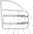
Fig. 1 is a front view of the present invention.
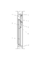
Fig. 2 is the A-A profile of Fig. 1.
Fig. 3 is the B-B profile of Fig. 1.
Fig. 4 is that Fig. 3 puts down the enforcement illustration when opening.
Enforcement illustration when Fig. 5 is Fig. 3 push-and-pull.
Partial sectional view when Fig. 6 is closing of the door.
Partial sectional view when Fig. 7 is car door opening.
Fig. 8 is embodiments of the invention figure.
Among the figure: 1. car door.2. connect seat.3. supporting arm.4. rocking bar.5. sliding sleeve.6. hinge seat.7. slide rail.8. cross groove.9. slot to make way.10. limited block.11. car door frame.
The specific embodiment
In Fig. 1, Fig. 2, Fig. 3, Fig. 4, Fig. 5, Fig. 6, slide rail 7 is horizontally set on the inboard of car door 1, and slide rail 7 is connected with car door 1 through termination, the left and right sides, on slide rail 7, offers two slots to make way 9.Sliding sleeve 5 is a tubular construction; Two hinge seats 6 about the right ends of sliding sleeve 5 is respectively arranged with; On left and right sides hinge seat 6, all offer with sliding sleeve 5 parallel axes cross groove 8, the groove 8 of crossing on the left and right sides hinge seat 6 all is communicated with the centre bore of sliding sleeve 5, sliding sleeve 5 is sleeved on the slide rail 7; When sliding sleeve 5 moves to the low order end position of slide rail 7, on two hinge seats 6 cross groove 8 respectively with slide rail 7 on two slots to make way 9 align and be communicated with.Connecting seat 2 is connected on the stile limit of car door frame 11; Supporting arm 3 is parallel with slide rail 7; The right-hand member head of supporting arm 3 is connected with connection seat 2; About the rear end of two rocking bars 4 be connected with the right ends hinge of supporting arm 3 respectively, about the front end of two rocking bars 4 be connected to crossing in the groove 8 of left and right sides hinge seat 6 on the sliding sleeve 5, be provided with limited block 10 in the left side of left rocker 4 front ends; When rocking bar 4 and slide rail 7 were vertical, the front end face of the front end face of rocking bar 4 and limited block 10 all overlapped with the external surface of slide rail 7.Sliding sleeve 5, left rocker 4 and supporting arm 3 common formation four-bar linkages.Car door 1 is provided with the some slide rails that are parallel to each other 7, and each one slide rail 7 all is connected with connection seat 2 through a four-bar linkage.
In Fig. 3, Fig. 4, Fig. 5, Fig. 6, Fig. 7, Fig. 8; When opening car door 1; Car door 1 with rocking bar 4 clockwise rotate and outwards flat opening; When rocking bar 4 rotates to when vertical with sliding sleeve 5 around hinge seat 6, the front end face of limited block 10 will continue to clockwise rotate through slide rail 7 common restriction rocking bars 4, and this moment, car door 1 can be through slide rail 7 and sliding sleeve 5 slide-open forward.During closed door 1; Slide backward car door 1 through slide rail 7 and sliding sleeve 5; When the groove excessively 8 of slot to make way on the slide rail 79 and sliding sleeve 5 upper hinge seats 6 misplaces; The front end face of the front end face of rocking bar 4 and limited block 10 will be through the common restriction of slide rail 7 rocking bar 4 left-right rotation, and when sliding sleeve 5 moved to the low order end position of slide rail 7, car door 1 can rotating counterclockwise and close with rocking bar 4.
Claims (4)
1. built-in slideway type push-and-pull car door, it comprises car door, connects seat, supporting arm, rocking bar, sliding sleeve, slide rail, hinge seat, mistake groove, slot to make way, limited block and car door frame, it is characterized in that: slide rail is horizontally set on the inboard of car door; Slide rail is connected with car door through termination, the left and right sides, on slide rail, offers two slots to make way, and sliding sleeve is a tubular construction; Two hinge seats about the right ends of sliding sleeve is respectively arranged with all offer the groove of crossing with the sliding sleeve parallel axes on the hinge seat of the left and right sides, the groove of crossing on the hinge seat of the left and right sides all is communicated with the centre bore of sliding sleeve; Sliding sleeve is sleeved on the slide rail; When sliding sleeve moves to the low order end position of slide rail, on two hinge seats cross groove respectively with slide rail on two slots to make way align and be communicated with, connect and be connected on the stile limit of car door frame; Supporting arm is parallel with slide rail; The right-hand member head of supporting arm with connect seat and be connected, about the rear end of two rocking bars be connected with the right ends hinge of supporting arm respectively, about the front end of two rocking bars be connected in the mistake groove of left and right sides hinge seat on the sliding sleeve; Left side at the left rocker front end is provided with limited block; When rocking bar was vertical with slide rail, the front end face of rocking bar and the front end face of limited block all overlapped with the external surface of slide rail, and sliding sleeve, left rocker and supporting arm constitute four-bar linkage jointly.
2. built-in slideway type push-and-pull car door according to claim 1, it is characterized in that: described car door is provided with the some slide rails that are parallel to each other, and each one slide rail all is connected with the connection seat through a four-bar linkage.
3. built-in slideway type push-and-pull car door according to claim 1 is characterized in that: described rocking bar rotates to when vertical with sliding sleeve around hinge seat, and the front end face of limited block will limit rocking bar jointly through slide rail to be continued to clockwise rotate.
4. built-in slideway type push-and-pull car door according to claim 1 is characterized in that: when the mistake groove of slot to make way on the slide rail and sliding sleeve upper hinge seat misplaces, the front end face of rocking bar and the front end face of limited block will limit the rocking bar left-right rotation jointly through slide rail.
Priority Applications (1)
| Application Number | Priority Date | Filing Date | Title |
|---|---|---|---|
| CN2012102372635A CN102733719A (en) | 2012-07-10 | 2012-07-10 | Sliding car door internally provided with sliding way |
Applications Claiming Priority (1)
| Application Number | Priority Date | Filing Date | Title |
|---|---|---|---|
| CN2012102372635A CN102733719A (en) | 2012-07-10 | 2012-07-10 | Sliding car door internally provided with sliding way |
Publications (1)
| Publication Number | Publication Date |
|---|---|
| CN102733719A true CN102733719A (en) | 2012-10-17 |
Family
ID=46989950
Family Applications (1)
| Application Number | Title | Priority Date | Filing Date |
|---|---|---|---|
| CN2012102372635A Pending CN102733719A (en) | 2012-07-10 | 2012-07-10 | Sliding car door internally provided with sliding way |
Country Status (1)
| Country | Link |
|---|---|
| CN (1) | CN102733719A (en) |
Cited By (3)
| Publication number | Priority date | Publication date | Assignee | Title |
|---|---|---|---|---|
| CN108222779A (en) * | 2018-03-16 | 2018-06-29 | 刘庆 | Pulling casement composite structure and soundproofed cabin |
| CN110329046A (en) * | 2019-06-24 | 2019-10-15 | 芜湖莫森泰克汽车科技股份有限公司 | Electric drive method and structure when a kind of realization arrangements for automotive doors swing arm |
| WO2021218586A1 (en) * | 2020-04-27 | 2021-11-04 | Ningbo Geely Automobile Research & Development Co., Ltd. | A door system for a vehicle and a vehicle comprising a door system |
Citations (6)
| Publication number | Priority date | Publication date | Assignee | Title |
|---|---|---|---|---|
| JPS6114901Y2 (en) * | 1981-02-12 | 1986-05-09 | ||
| JPH09277833A (en) * | 1996-04-12 | 1997-10-28 | Otec Japan:Kk | Slide type door opening and closing device for vehicle |
| US5921613A (en) * | 1996-08-26 | 1999-07-13 | Daimler-Benz Aktiengesellschaft | Arrangement for guiding a swing-out sliding door on a vehicle body |
| US20040108749A1 (en) * | 2002-05-30 | 2004-06-10 | Compagnie Plastic Omnium | Mechanism for guiding a sliding door, a sliding door, and a motor vehicle provided with such a mechanism |
| WO2006005572A1 (en) * | 2004-07-13 | 2006-01-19 | Daimlerchrysler Ag | Sliding door system |
| CN202645317U (en) * | 2012-07-10 | 2013-01-02 | 张卫 | Internally-installed sliding path type push-pull car door |
-
2012
- 2012-07-10 CN CN2012102372635A patent/CN102733719A/en active Pending
Patent Citations (6)
| Publication number | Priority date | Publication date | Assignee | Title |
|---|---|---|---|---|
| JPS6114901Y2 (en) * | 1981-02-12 | 1986-05-09 | ||
| JPH09277833A (en) * | 1996-04-12 | 1997-10-28 | Otec Japan:Kk | Slide type door opening and closing device for vehicle |
| US5921613A (en) * | 1996-08-26 | 1999-07-13 | Daimler-Benz Aktiengesellschaft | Arrangement for guiding a swing-out sliding door on a vehicle body |
| US20040108749A1 (en) * | 2002-05-30 | 2004-06-10 | Compagnie Plastic Omnium | Mechanism for guiding a sliding door, a sliding door, and a motor vehicle provided with such a mechanism |
| WO2006005572A1 (en) * | 2004-07-13 | 2006-01-19 | Daimlerchrysler Ag | Sliding door system |
| CN202645317U (en) * | 2012-07-10 | 2013-01-02 | 张卫 | Internally-installed sliding path type push-pull car door |
Cited By (5)
| Publication number | Priority date | Publication date | Assignee | Title |
|---|---|---|---|---|
| CN108222779A (en) * | 2018-03-16 | 2018-06-29 | 刘庆 | Pulling casement composite structure and soundproofed cabin |
| CN108222779B (en) * | 2018-03-16 | 2024-10-08 | 刘庆 | Sliding and opening composite structure and soundproof cabin |
| CN110329046A (en) * | 2019-06-24 | 2019-10-15 | 芜湖莫森泰克汽车科技股份有限公司 | Electric drive method and structure when a kind of realization arrangements for automotive doors swing arm |
| WO2021218586A1 (en) * | 2020-04-27 | 2021-11-04 | Ningbo Geely Automobile Research & Development Co., Ltd. | A door system for a vehicle and a vehicle comprising a door system |
| US12037828B2 (en) | 2020-04-27 | 2024-07-16 | Ningbo Geely Automobile Research & Development Co., Ltd. | Door system for a vehicle and a vehicle comprising a door system |
Similar Documents
| Publication | Publication Date | Title |
|---|---|---|
| CN202645317U (en) | Internally-installed sliding path type push-pull car door | |
| CN104108298B (en) | Door structure | |
| CN102733719A (en) | Sliding car door internally provided with sliding way | |
| JP2009523937A (en) | Lifting device for two-plate folding door | |
| CN109267869A (en) | A kind of assembling structure of imbedded hinge | |
| CN106223760B (en) | A kind of upset linkage damping mechanism for furniture | |
| US2685102A (en) | Gravity closing two-way swinging door hinge | |
| CN107585217A (en) | Electric car charging interface lid structure | |
| CN207999160U (en) | A kind of position-limit mechanism for furniture revolution push-and-pull opening and closing | |
| CN210217524U (en) | Improved sliding shaft shower room door | |
| CN203172677U (en) | Stroller | |
| CN108798333A (en) | A kind of furniture simply overturns structure | |
| CN109838165A (en) | A kind of buffer unit of tilt-up door hinge | |
| CN206158425U (en) | Furniture turning device's angle limiting mechanism | |
| CN201513076U (en) | Cabinet door with two opening manners | |
| CN106477907B (en) | A kind of plated film case with linkage door close | |
| CN102106658B (en) | Drawer slide rail part | |
| CN102852432B (en) | Inward falling sliding window | |
| CN205189583U (en) | Door and window hinge | |
| CN105201354B (en) | A kind of adjacent door leaf interlinked mechanism of folding door | |
| CN202378667U (en) | Novel multifunctional business purpose vehicle side window | |
| CN101096810A (en) | U-shaped door hinge setup modus | |
| CN102431420B (en) | Novel multifunctional side window of business car | |
| CN204343851U (en) | A kind of slide rail type hinge | |
| CN211315676U (en) | Support device of point reading machine |
Legal Events
| Date | Code | Title | Description |
|---|---|---|---|
| C06 | Publication | ||
| PB01 | Publication | ||
| C10 | Entry into substantive examination | ||
| SE01 | Entry into force of request for substantive examination | ||
| C02 | Deemed withdrawal of patent application after publication (patent law 2001) | ||
| WD01 | Invention patent application deemed withdrawn after publication |
Application publication date: 20121017 |