CN102733885A - System and method for monitoring engine oil levels - Google Patents
System and method for monitoring engine oil levels Download PDFInfo
- Publication number
- CN102733885A CN102733885A CN2012100988981A CN201210098898A CN102733885A CN 102733885 A CN102733885 A CN 102733885A CN 2012100988981 A CN2012100988981 A CN 2012100988981A CN 201210098898 A CN201210098898 A CN 201210098898A CN 102733885 A CN102733885 A CN 102733885A
- Authority
- CN
- China
- Prior art keywords
- oil
- determination module
- fluid
- engine
- temperature
- Prior art date
- Legal status (The legal status is an assumption and is not a legal conclusion. Google has not performed a legal analysis and makes no representation as to the accuracy of the status listed.)
- Granted
Links
- 238000000034 method Methods 0.000 title claims description 79
- 238000012544 monitoring process Methods 0.000 title abstract description 13
- 239000010705 motor oil Substances 0.000 title description 17
- 239000012530 fluid Substances 0.000 claims abstract description 49
- 239000007788 liquid Substances 0.000 claims abstract description 22
- 230000004044 response Effects 0.000 claims abstract description 15
- 230000015654 memory Effects 0.000 claims description 11
- 230000005484 gravity Effects 0.000 claims description 7
- 238000005259 measurement Methods 0.000 claims 1
- 239000003921 oil Substances 0.000 description 246
- 239000000446 fuel Substances 0.000 description 10
- 239000000203 mixture Substances 0.000 description 6
- 238000002485 combustion reaction Methods 0.000 description 5
- 238000010586 diagram Methods 0.000 description 4
- 238000004590 computer program Methods 0.000 description 3
- 230000006870 function Effects 0.000 description 3
- 230000006835 compression Effects 0.000 description 2
- 238000007906 compression Methods 0.000 description 2
- 238000005086 pumping Methods 0.000 description 2
- 230000005540 biological transmission Effects 0.000 description 1
- 230000007423 decrease Effects 0.000 description 1
- 238000012986 modification Methods 0.000 description 1
- 230000004048 modification Effects 0.000 description 1
- 230000003287 optical effect Effects 0.000 description 1
Images


Classifications
-
- F—MECHANICAL ENGINEERING; LIGHTING; HEATING; WEAPONS; BLASTING
- F01—MACHINES OR ENGINES IN GENERAL; ENGINE PLANTS IN GENERAL; STEAM ENGINES
- F01M—LUBRICATING OF MACHINES OR ENGINES IN GENERAL; LUBRICATING INTERNAL COMBUSTION ENGINES; CRANKCASE VENTILATING
- F01M11/00—Component parts, details or accessories, not provided for in, or of interest apart from, groups F01M1/00 - F01M9/00
- F01M11/10—Indicating devices; Other safety devices
- F01M11/12—Indicating devices; Other safety devices concerning lubricant level
Landscapes
- Engineering & Computer Science (AREA)
- Mechanical Engineering (AREA)
- General Engineering & Computer Science (AREA)
- Lubrication Details And Ventilation Of Internal Combustion Engines (AREA)
Abstract
本发明提供一种监测发动机的油液位的系统,该系统包括用户接口模块、液位确定模块、和液位存储模块。用户接口模块基于用户输入而输出油液位请求。液位确定模块确定发动机的N个油液位。N是大于1的整数。液位存储模块存储N个油液位,并且响应于油液位请求而输出N个油液位之一。

The invention provides a system for monitoring the oil level of an engine. The system includes a user interface module, a liquid level determination module, and a liquid level storage module. A user interface module outputs an oil level request based on user input. The fluid level determination module determines N oil fluid levels of the engine. N is an integer greater than 1. The level storage module stores N oil levels and outputs one of the N oil levels in response to an oil level request.
Description
技术领域 technical field
本发明涉及发动机控制系统和方法,更具体地,涉及用于监测发动机油液位的系统和方法。 The present invention relates to engine control systems and methods, and more particularly, to systems and methods for monitoring engine oil level.
背景技术 Background technique
此处提供的背景技术的描述的目的是总体地给出本公开的背景。当前署名的发明人的工作,在该背景技术部分所描述的程度,以及在提交时可能不构成现有技术的本发明的方面并非明示或暗示地接受为本公开的现有技术。 The background description provided herein is for the purpose of generally presenting the context of the disclosure. The work of the presently named inventors, to the extent described in this Background section, and aspects of the invention that may not have constituted prior art at the time of filing are not admitted, expressly or by implication, to be prior art to the present disclosure.
发动机油通常在发动机内循环以润滑发动机内的运动构件。通常,油泵将发动机油从油储槽泵送到发动机内的各种其它位置。重力造成发动机油返回至油储槽。当发动机被关闭时,油泵不再泵送发动机油,并且因此发动机油的大部分返回至油储槽并保留在油储槽中。 Engine oil is typically circulated within the engine to lubricate the moving components within the engine. Typically, an oil pump pumps engine oil from an oil sump to various other locations within the engine. Gravity causes the engine oil to return to the oil sump. When the engine is turned off, the oil pump is no longer pumping engine oil, and therefore most of the engine oil returns to and remains in the oil sump.
当发动机运行时,发动机油必须保持在一定液位之上以防止对发动机构件造成损害。已经开发出了这样的方法,即,当发动机关闭时,操作员通过从油储槽取出量油计并且观察沉积在量油计上的油的量而手动地检查发动机油液位。然而,这些方法依赖于操作员来检查发动机油液位,因此可能导致不经常检查油液位、低或高的发动机油液位,并且最终损害发动机和/或排放控制系统。 When the engine is running, the engine oil must be kept above a certain level to prevent damage to the engine components. Methods have been developed whereby an operator manually checks the engine oil level when the engine is shut down by removing the dipstick from the oil sump and observing the amount of oil deposited on the dipstick. However, these methods rely on an operator to check the engine oil level and thus may result in infrequent oil level checks, low or high engine oil levels, and ultimately damage to the engine and/or emission control system.
发明内容 Contents of the invention
一种系统,该系统包括用户接口模块、液位确定模块、和液位存储模块。用户接口模块基于用户输入而输出油液位请求。液位确定模块确定发动机的N个油液位。N是大于1的整数。液位存储模块存储N个油液位,并且响应于油液位请求而输出N个油液位之一。 A system includes a user interface module, a fluid level determination module, and a fluid level storage module. A user interface module outputs an oil level request based on user input. The fluid level determination module determines N oil fluid levels of the engine. N is an integer greater than 1. The level storage module stores N oil levels and outputs one of the N oil levels in response to an oil level request.
此外,本发明还涉及以下技术方案。 In addition, the present invention also relates to the following technical solutions.
1. 一种系统,包括: 1. A system comprising:
基于用户输入而输出油液位请求的用户接口模块; a user interface module that outputs an oil level request based on user input;
确定发动机的N个油液位的液位确定模块;以及 a fluid level determination module for determining N oil fluid levels of the engine; and
液位存储模块,所述液位存储模块存储所述N个油液位,并且响应于所述油液位请求而输出所述N个油液位之一,其中,N为大于1的整数。 A liquid level storage module, the liquid level storage module stores the N oil levels, and outputs one of the N oil levels in response to the oil level request, where N is an integer greater than 1.
2. 如技术方案1所述的系统,还包括油液位传感器,所述油液位传感器测量油液位,并且输出指示所述N个油液位的油液位信号,其中,所述液位确定模块基于所述油液位信号而确定所述N个油液位。 2. The system according to technical solution 1, further comprising an oil level sensor, the oil level sensor measures the oil level, and outputs an oil level signal indicating the N oil levels, wherein the oil level sensor A level determination module determines the N oil levels based on the oil level signal.
3. 如技术方案1所述的系统,还包括确定所述发动机的油温的温度确定模块,其中,所述液位确定模块基于所述油温来确定所述N个油液位。 3. The system according to technical solution 1, further comprising a temperature determination module for determining the oil temperature of the engine, wherein the liquid level determination module determines the N oil liquid levels based on the oil temperature.
4. 如技术方案3所述的系统,还包括温度传感器,所述温度传感器测量油温,并且输出指示油温的油温信号,其中,所述温度确定模块基于所述油温信号而确定油温。 4. The system according to technical solution 3, further comprising a temperature sensor, the temperature sensor measures the oil temperature, and outputs an oil temperature signal indicating the oil temperature, wherein the temperature determination module determines the oil temperature based on the oil temperature signal temperature.
5. 如技术方案3所述的系统,其中,当所述油温大于预先确定的温度时,所述液位确定模块确定所述N个油液位。 5. The system according to technical solution 3, wherein, when the oil temperature is greater than a predetermined temperature, the liquid level determining module determines the N oil liquid levels.
6. 如技术方案3所述的系统,还包括时间确定模块,所述时间确定模块确定油被允许泄放进入发动机的油储存器中的泄放时间,其中,当发动机关闭时间大于所述泄放时间时,所述液位确定模块确定所述N个油液位。 6. The system according to technical solution 3, further comprising a time determination module, the time determination module determines the discharge time that oil is allowed to discharge into the oil reservoir of the engine, wherein, when the engine off time is longer than the discharge time During discharge time, the liquid level determining module determines the N oil liquid levels.
7. 如技术方案6所述的系统,其中,所述时间确定模块基于油温、发动机类型、和油粘度等级中的至少一个来确定所述泄放时间。 7. The system of claim 6, wherein the time determination module determines the bleed time based on at least one of oil temperature, engine type, and oil viscosity grade.
8. 如技术方案1所述的系统,还包括确定车辆相对于重力的倾斜度的倾斜度确定模块,其中,当车辆的倾斜度小于预先确定的角度时,所述液位确定模块确定所述N个油液位。 8. The system according to technical solution 1, further comprising an inclination determination module for determining the inclination of the vehicle relative to gravity, wherein, when the inclination of the vehicle is less than a predetermined angle, the liquid level determination module determines the N oil levels.
9. 如技术方案1所述的系统,其中,所述液位确定模块响应于所述油液位请求而确定所述N个油液位之一。 9. The system according to technical solution 1, wherein the fluid level determination module determines one of the N oil levels in response to the oil level request.
10. 如技术方案1所述的系统,其中,利用无线信号传递所述油液位请求和所述油液位。 10. The system according to technical solution 1, wherein the oil level request and the oil level are communicated using wireless signals.
11. 一种方法,包括: 11. A method comprising:
基于用户输入而输出油液位请求; outputting an oil level request based on user input;
确定发动机的N个油液位;以及 determining N oil levels of the engine; and
在非易失性存储器中存储所述N个油液位,并且响应于所述油液位请求而输出所述N个油液位之一,其中,N为大于1的整数。 The N oil levels are stored in a non-volatile memory, and one of the N oil levels is output in response to the oil level request, where N is an integer greater than 1.
12. 如技术方案11所述的方法,还包括: 12. The method as described in technical scheme 11, further comprising:
测量油液位,并且输出指示所述N个油液位的油液位信号;以及 measuring oil levels and outputting oil level signals indicative of said N oil levels; and
基于所述油液位信号确定所述N个油液位。 The N oil levels are determined based on the oil level signal.
13. 如技术方案11所述的方法,还包括: 13. The method as described in technical scheme 11, further comprising:
确定所述发动机的油温;以及 determining the oil temperature of the engine; and
基于所述油温确定所述N个油液位。 The N oil levels are determined based on the oil temperature.
14. 如技术方案13所述的方法,还包括: 14. The method as described in technical scheme 13, further comprising:
输出指示油温的油温信号;以及 outputting an oil temperature signal indicative of oil temperature; and
基于所述油温信号确定所述油温。 The oil temperature is determined based on the oil temperature signal.
15. 如技术方案13所述的方法,还包括:当所述油温大于预先确定的温度时,确定所述N个油液位。 15. The method according to technical solution 13, further comprising: determining the N oil levels when the oil temperature is greater than a predetermined temperature.
16. 如技术方案13所述的方法,还包括: 16. The method as described in technical scheme 13, further comprising:
确定油被允许泄放进入所述发动机的油储存器的泄放时间;以及 determining a drain time for oil to be allowed to drain into an oil reservoir of the engine; and
当发动机关闭时间大于所述泄放时间时,确定所述N个油液位。 The N oil levels are determined when the engine off time is greater than the drain time.
17. 如技术方案16所述的方法,还包括:基于油温、发动机类型、和油粘度等级中的至少一个来确定所述泄放时间。 17. The method according to technical solution 16, further comprising: determining the bleed time based on at least one of oil temperature, engine type, and oil viscosity grade.
18. 如技术方案11所述的方法,还包括: 18. The method as described in technical scheme 11, further comprising:
确定车辆相对于重力的倾斜度;以及 determine the vehicle's inclination relative to gravity; and
当车辆的倾斜度小于预先确定的角度时确定所述N个油液位。 The N oil levels are determined when the inclination of the vehicle is less than a predetermined angle.
19. 如技术方案11所述的方法,还包括:响应于所述油液位请求而确定所述N个油液位之一。 19. The method according to technical solution 11, further comprising: determining one of the N oil levels in response to the oil level request.
20. 如技术方案11所述的方法,其中,利用无线信号传递所述油液位请求和所述油液位。 20. The method according to technical solution 11, wherein the oil level request and the oil level are communicated using wireless signals.
本公开的可应用的其它领域将从以下提供的详细说明变得清楚。应该理解,详细说明和具体实例仅是用于说明的目的,并且不限定本公开的范围。 Other fields of applicability of the present disclosure will become apparent from the detailed description provided below. It should be understood that the detailed description and specific examples are intended for purposes of illustration only and are not intended to limit the scope of the present disclosure.
附图说明 Description of drawings
从详细说明及附图,本公开将被更完全地理解,附图中: The disclosure will be more fully understood from the detailed description and accompanying drawings, in which:
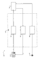
图1是根据本发明原理的示例发动机系统的功能框图; 1 is a functional block diagram of an example engine system in accordance with the principles of the present invention;
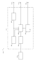
图2是根据本发明原理的示例用户接口模块的功能框图; Figure 2 is a functional block diagram of an example user interface module in accordance with the principles of the present invention;
图3是根据本发明原理的示例发动机控制模块的功能框图;和 3 is a functional block diagram of an example engine control module in accordance with the principles of the present invention; and
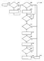
图4和图5是示出根据本发明原理的监测发动机油的示例方法的流程图。 4 and 5 are flowcharts illustrating example methods of monitoring engine oil according to the principles of the present invention.
具体实施方式 Detailed ways
以下描述在本质上仅仅是说明性的,并且绝不意图限制本公开,其应用或用途。为了清楚,在附图中使用相同的标号来表示相似的元件。如本文所用,短语A,B和C中的至少一个应被理解为表示逻辑(A或B或C),使用的是非排他的逻辑或。应该懂得,方法中的步骤可以以不同的顺序执行,而不改变本公开的原理。 The following description is merely illustrative in nature and is in no way intended to limit the disclosure, its application or uses. For purposes of clarity, the same reference numbers are used in the drawings to refer to similar elements. As used herein, the phrase at least one of A, B, and C should be understood to mean a logical (A or B or C), using a non-exclusive logical or. It should be understood that steps within a method may be executed in different order without altering the principles of the present disclosure.
如本文所用,术语模块可以指一部分为或包括:专用集成电路(ASIC);电路;组合逻辑电路;场可编程门阵列(FPGA);执行代码的处理器(共享的、专用的或成组的);提供所需功能的其它合适的构件;或者以上所述的一些的组合,诸如片上系统。术语模块可包括存储由处理器执行的代码的存储器(共享的、专用的或成组的)。 As used herein, the term module may refer to a portion that is or includes: an application specific integrated circuit (ASIC); a circuit; a combinational logic circuit; a field programmable gate array (FPGA); a processor (shared, dedicated, or grouped) that executes code; ); other suitable components that provide the required functions; or a combination of some of the above, such as a system on a chip. The term module may include memory (shared, dedicated or grouped) that stores code for execution by a processor.
术语代码,如以上用,可包括软件、固件和/或微代码,并且可以指程序、例程、函数、类和/或对象。术语共享的,如上所用,指的是来自多个模块的一些或所有代码可以利用单个(共享的)处理器来执行。另外,来自多个模块的一些或所有代码可以由单个(共享的)存储器来存储。术语成组的,如上所用,指的是来自单个模块的一些或所有代码可以利用一组处理器来执行。另外,来自单个模块的一些或所有代码可以利用一组存储器来存储。 The term code, as used above, may include software, firmware, and/or microcode, and may refer to programs, routines, functions, classes, and/or objects. The term shared, as used above, means that some or all code from multiple modules can be executed using a single (shared) processor. Additionally, some or all code from multiple modules may be stored by a single (shared) memory. The term grouped, as used above, means that some or all code from a single module can be executed by a group of processors. Additionally, some or all code from a single module may be stored using a set of memories.
本文所述的装置和方法可以由一个或多个处理器所执行的一个或多个计算机程序来实施。计算机程序包括存储在非暂时性有形计算机可读介质上的处理器可执行指令。计算机程序还可以包括存储的数据。非暂时性有形计算机可读介质的非限制性示例是非易失性存储器、磁存储装置和光学存储装置。 The apparatus and methods described herein may be implemented by one or more computer programs executed by one or more processors. Computer programs include processor-executable instructions stored on a non-transitory tangible computer readable medium. A computer program may also include stored data. Non-limiting examples of non-transitory tangible computer readable media are non-volatile memory, magnetic storage, and optical storage.
根据本发明原理的发动机油液位监测系统和方法自动地检测发动机的油液位,使得用户能够请求油液位检查,并且响应于用户的请求而显示油液位。油液位可以使用油液位传感器来测量。用户可以使用仪表板、移动装置和/或互联网来请求油液位。响应于用户的请求,可以基于油监测情况来确定油液位。 An engine oil level monitoring system and method in accordance with the principles of the present invention automatically detects the oil level of an engine, enables a user to request an oil level check, and displays the oil level in response to the user's request. Oil level can be measured using an oil level sensor. A user may request the oil level using a dashboard, a mobile device, and/or the Internet. The oil level may be determined based on the oil monitoring conditions in response to a user request.
油监测情况可以包括油温、发动机关闭时间、和/或车辆倾斜度。当油温大于预先确定的温度、发动机关闭时间大于泄放时间、和/或车辆倾斜度小于预先确定的角度时,可以确定油液位。可以基于油温来修改油液位,油温可以利用温度传感器来测量。在泄放时间期间,允许油泄放到油储存器中,泄放时间可以基于油温、发动机类型、和/或油粘度等级来确定。 Oil monitoring conditions may include oil temperature, engine off time, and/or vehicle inclination. The oil level may be determined when the oil temperature is greater than a predetermined temperature, the engine is off for more than a drain time, and/or the vehicle incline is less than a predetermined angle. The oil level may be modified based on oil temperature, which may be measured using a temperature sensor. Oil is allowed to drain into the oil reservoir during a drain time, which may be determined based on oil temperature, engine type, and/or oil viscosity grade.
现在参考图1,示出了示例性发动机系统100的功能框图。发动机102产生用于车辆的驱动扭矩。虽然发动机102被示出并将作为火花点火类型来论述,但是发动机102可以是另一适当类型的发动机,例如压缩点火发动机。
Referring now to FIG. 1 , a functional block diagram of an
空气通过进气歧管104被吸入发动机102。可以使用节气门阀106改变进入发动机102的气流。一个或多个燃料喷射器,例如燃料喷射器108,使燃料与空气混合以形成空气/燃料混合物。空气/燃料混合物在发动机102的气缸(例如气缸110)内燃烧。尽管发动机102被描述为包括一个气缸,但发动机102可以包括多于一个的气缸。
Air is drawn into the
气缸110包括被机械地连接到曲轴112的活塞(未示出)。气缸110内的一个燃烧循环可以包括4个阶段:进气阶段、压缩阶段、燃烧阶段、和排气阶段。在进气阶段,活塞向最底位置移动并将空气吸入气缸110中。在压缩阶段,活塞向最顶位置移动并压缩气缸110内的空气或空气/燃料混合物。
在燃烧阶段期间,来自火花塞114的火花点燃空气/燃料混合物。空气/燃料混合物的燃烧驱动活塞向后朝向最底位置,并且活塞驱动曲轴112的旋转。产生的排气从气缸110通过排气歧管116排出以完成排气阶段和燃烧循环。发动机102经由曲轴112将扭矩输出给变速器(未示出)。
During the combustion phase, a spark from
油储存器118(诸如油储槽)存储润滑发动机102内的运动部件的油,并且可以位于发动机102的底部或底部附近。当发动机102运行时,油储槽(未示出)可以将油从油储存器118泵送到发动机102内的其它位置。重力可能造成油返回到油储存器118。当发动机102被关闭时,油泵可以停止泵送油,油的大部分可以返回至油储存器118并保留在油储存器118中。
An
发动机控制模块(ECM)120基于从一个或多个传感器接收到的输入而控制节气门阀106、燃料喷射器108、和火花塞114,并且确定倾斜角、油温和发动机102的油液位。ECM120可以基于发动机102的油液位来控制节气门阀106、燃料喷射器108和火花塞114。例如,当油液位低时,ECM120可以限制发动机102的速度。
An engine control module (ECM) 120 controls the
传感器可以包括温度传感器122、油液位传感器124、和倾斜度传感器126。温度传感器122测量发动机102内的油的温度,并且输出指示油温的油温信号。油液位传感器124测量发动机102内的油液位,并且输出指示油液位的油液位信号。倾斜度传感器126测量车辆相对于重力的倾斜度,并输出指示车辆倾斜度的车辆倾斜度信号。
The sensors may include a
温度传感器122和油液位传感器124可以集成在一个传感器中。油液位传感器124可以位于油储存器118的底部,并且可以通过将超声波传递到油储存器中的油内而测量油液位。油液位传感器124可以测量超声波从油的上表面反射回到油液位传感器124所经历的时间。油液位传感器124可以基于该经过的时间测量油液位。
The
用户接口模块(UIM)128使得用户能够请求油液位检查并利用显示装置130(诸如触摸屏)将油液位显示给用户。UIM128和/或显示装置130可以包括在仪表板、移动装置、膝上型计算机或桌面计算机中。UIM128利用有线或无线信号而将用户请求输出给ECM120,ECM120响应于用户请求利用有线或无线信号将油液位输出给UIM128。
A user interface module (UIM) 128 enables a user to request an oil level check and displays the oil level to the user using a
点火钥匙或按钮132使用户能够起动和停止发动机102。点火钥匙或按钮132可以将发动机起动/停止信号输出给UIM128,其可将发动机起动/停止信号传递给ECM120。或者,点火钥匙或按钮132可以直接地将发动机起动/停止信号输出给ECM120。ECM120响应于发动机起动/停止信号而起动和停止发动机102。
An ignition key or
现在参考图2,发动机油液位监测系统200包括ECM120、UIM128、和显示装置130。UIM128包括请求产生模块202、显示确定模块204和发动机关闭计时器模块206。请求产生模块202从显示装置130接收用户输入,并且基于用户输入产生油液位请求。
Referring now to FIG. 2 , engine oil
请求产生模块202将油液位请求输出给ECM120,ECM120响应于油液位请求而将油液位输出给显示确定模块204。油液位请求可以是先前液位请求或当前液位请求。先前液位请求请求先前的油液位,其可以是最近测量的油液位。当前液位请求请求当前的油液位,其在油液位监测条件满足某些准则时测量,诸如当发动机102关闭达到预先确定的时间量并且车辆是水平时。
The
显示确定模块204控制显示装置130以显示从ECM120接收到的油液位。在当前油液位被请求时,ECM120可以通知显示确定模块204ECM120接收到了当前液位请求。从而,显示确定模块204可以控制显示装置130以显示告知收到当前液位请求的用户消息。例如,用户消息可以指示用户将车辆停在水平地面上,并且通知用户将在发动机102关闭之后的下一机会进行油液位检查。
The display determination module 204 controls the
发动机关闭计时器模块206确定发动机关闭时间,该时间从发动机102被关闭时开始并且可以在发动机102被启动时结束。发动机关闭计时器模块206可以基于从点火钥匙或按钮132接收到的输入来确定发动机关闭时间。例如,当点火钥匙或按钮132被按下以关闭发动机102时,发动机关闭计时器模块206可以开始增加发动机关闭时间。发动机关闭计时器模块206可以将发动机关闭时间输出给ECM120。
The engine off timer module 206 determines an engine off time that begins when the
现在参考图3,发动机油液位监测系统300包括ECM120、温度传感器122、油液位传感器124、倾斜度传感器126、和UIM128。系统200、300可以集成为单一的系统并且可以包括任一系统的元件。ECM120包括温度确定模块302、倾斜度确定模块304、泄放时间确定模块306、液位确定模块308、以及液位存储模块310。
Referring now to FIG. 3 , engine oil
温度确定模块302确定油温。温度确定模块302可以基于油温信号和油温信号与油温之间的预先限定的关系而确定油温。此关系可以实现为等式和/或查询表。或者,温度确定模块302可以基于车辆操作条件(诸如,环境温度和发动机开启时间(即,发动机102开启期间的时间))来确定油温。温度确定模块302输出油温。
The
倾斜度确定模块304确定车辆相对于重力的倾斜度。倾斜度确定模块304可以基于车辆倾斜度信号和车辆倾斜度信号与车辆倾斜度之间的预先限定的关系而确定车辆倾斜度。此关系可以实现为等式和/或查询表。倾斜度确定模块304输出车辆倾斜度。
The
泄放时间确定模块306确定泄放时间。泄放时间是在发动机102关闭时油被允许泄放回油储存器118的时间(例如,在2分钟和30分钟之间)。泄放时间确定模块306可以基于油温、发动机类型、和/或油粘度等级来确定泄放时间。泄放时间确定模块306可以利用将一个或多个这些因素与泄放时间联系起来的等式和/或查询表来确定泄放时间。泄放时间确定模块306输出泄放时间。
The bleed
油粘度等级是在基准温度的油的粘度。油粘度等级可以影响泄放时间,因为具有较高粘度等级的油比具有较低粘度等级的油泄放得慢。油温可以影响泄放时间,因为油粘度与油温直接相关。因此,当油被加热时,油的粘度降低,油泄放得更快。相反地,当油被冷却时,油的粘度增加,油泄放得更慢。发动机类型可以影响泄放时间,因为不同的发动机类型可以具有不同的油通路构造,诸如不同的油通路直径,其可以影响油流量。 The oil viscosity grade is the viscosity of the oil at a reference temperature. The oil viscosity grade can affect the drain time because oils with higher viscosity grades drain more slowly than oils with lower viscosity grades. Oil temperature can affect drain time because oil viscosity is directly related to oil temperature. Therefore, when the oil is heated, the viscosity of the oil decreases and the oil drains faster. Conversely, when the oil is cooled, the viscosity of the oil increases and the oil drains more slowly. Engine type can affect bleed time because different engine types can have different oil passage configurations, such as different oil passage diameters, which can affect oil flow.
液位确定模块308确定发动机102的油液位。液位确定模块308可以基于油液位信号和油液位信号与油液位之间的预先限定的关系而确定油液位。或者,液位确定模块308可以基于油液位信号、油温、和油液位信号、油温与油液位之间的预先限定的关系而确定油液位。这些关系可以实现为方程和/或查询表。液位确定模块308输出油液位。
The fluid
液位确定模块308可以在预先确定的时间确定油液位和/或当由液位存储模块310指令时确定油液位。预先确定的时间可以用车辆里程(例如,每500英里)、发动机102已经操作的小时数(例如,每10个小时)、和/或发动机102被关闭的次数(例如,每5次)来规定。
The fluid
另外,当油监测条件满足某些准则时,诸如当发动机102关闭并且车辆是水平时,液位确定模块308可以确定油液位。例如,当油温大于预先确定的温度、发动机关闭时间大于泄放时间、和/或车辆倾斜度小于预先确定的角度(例如,30度)时,液位确定模块308可以确定油液位。液位确定模块308可以通过液位存储模块310从UIM128接收发动机关闭时间,或者液位确定模块308可以直接从UIM128接收发动机关闭时间。
Additionally, the fluid
液位存储模块310存储油液位,并且基于油液位请求而将油液位输出给UIM128。当油液位请求是先前的油液位请求时,液位存储模块310可以将先前的油液位输出给UIM128。先前的油液位可以是最近测量的油液位。在油液位请求是当前油液位请求时,液位存储模块310可以通知UIM128ECM120接收到了当前液位请求。另外,液位存储模块310可以指令液位确定模块308确定当前油液位。作为响应,液位确定模块308可以确定当前油液位并可将当前油液位输出给液位存储模块310。液位存储模块310然后可以将当前油液位输出给UIM128。
The level storage module 310 stores the oil level and outputs the oil level to the
现在参考图4,发动机油监测方法400开始于402。方法400可以由UIM128执行。在404,方法400确定用户是否已经请求了先前油液位。先前的油液位可以是最近测量的油液位。如果404为真,则该方法400继续至406。否则,方法400继续至408。
Referring now to FIG. 4 , engine
在406,方法400利用有线或无线信号将先前液位请求输出给车辆模块,诸如ECM。在410,方法400确定是否从车辆模块接收到先前油液位。如果410为真,则该方法400继续至412。在412,方法400显示先前油液位。方法400还可显示对应于先前油液位的日期、时间、和车辆里程。
At 406 ,
在408,方法400确定用户是否已经请求了当前油液位。如果408为真,则该方法400继续至414。否则,方法400在416结束。在414,方法400将当前液位请求输出给车辆模块。方法400可以利用有线或无线信号输出当前液位请求。在418,方法400确定车辆模块是否接收到当前液位请求。如果418为真,方法400继续至420,并且显示消息,该消息可指令用户在水平地面上停车并且通知用户将在关闭之后的下一机会进行油液位检查。
At 408 ,
在422,方法400确定是否已经从车辆模块接收到当前油液位。如果422为真,则该方法400继续至424。在424,方法400显示当前油液位。方法400还可显示对应于当前油液位的日期、时间、和车辆里程。
At 422 ,
现在参考图5,发动机油监测方法500开始于502。方法400、500可以集成为单一的方法并且可以包括任一方法的步骤。方法500可以由ECM120执行。在504,方法500确定是否请求了先前油液位。先前的油液位可以是最近测量的油液位。如果504为真,则该方法500继续至506。否则,方法500继续至508。
Referring now to FIG. 5 , engine oil monitoring method 500 begins at 502 . The
在506,方法500输出先前油液位。方法500可以利用有线或无线信号将先前油液位输出给车辆模块和/或远离车辆的模块。车辆模块可以包括在仪表板中。远程模块可以包括在移动装置、膝上型计算机和/或桌面计算机中。方法500还可输出对应于先前油液位的日期、时间、和车辆里程。 At 506 , method 500 outputs the previous oil level. Method 500 may output the previous oil level to a vehicle module and/or a module remote from the vehicle using a wired or wireless signal. Vehicle modules can be included in the dashboard. The remote module can be included in a mobile device, a laptop computer and/or a desktop computer. Method 500 may also output the date, time, and vehicle mileage corresponding to the previous oil level.
在508,方法500确定是否请求了当前油液位。如果508为真,则该方法500继续至510。否则,方法500在512结束。在510,方法500输出告知收到当前液位请求的用户消息。方法500可以将用户消息输出给车辆模块和/或远程模块。用户消息可以显示在仪表板、移动装置、膝上型计算机和/或桌面计算机上。 At 508 , method 500 determines whether a current oil level is requested. If 508 is true, the method 500 continues to 510 . Otherwise, method 500 ends at 512 . At 510, method 500 outputs a user message informing the receipt of the current level request. Method 500 may output user messages to the vehicle module and/or the remote module. User messages can be displayed on dashboards, mobile devices, laptops and/or desktops.
在514,方法500确定发动机是否被关闭。如果514为真,则该方法500继续至516。在516,方法500确定车辆倾斜度是否小于预先确定的角度(例如,30度)。如果516为真,则该方法500继续至518。否则,方法500在512结束。 At 514 , method 500 determines whether the engine is shut off. If 514 is true, the method 500 continues to 516 . At 516 , method 500 determines whether the vehicle incline is less than a predetermined angle (eg, 30 degrees). If 516 is true, the method 500 continues to 518 . Otherwise, method 500 ends at 512 .
在518,方法500确定油温。方法500可以利用温度传感器确定油温。在520,方法500确定油温是否大于预先确定的温度。预先确定的温度可以是在低于该温度时油液位传感器不能正常工作的温度(例如,零摄氏度)。如果520为真,则该方法500继续至522。 At 518 , method 500 determines oil temperature. Method 500 may utilize a temperature sensor to determine oil temperature. At 520 , method 500 determines if the oil temperature is greater than a predetermined temperature. The predetermined temperature may be a temperature below which the oil level sensor does not function properly (eg, zero degrees Celsius). If 520 is true, the method 500 continues to 522 .
在522,方法500确定泄放时间。泄放时间是在发动机关闭时油被允许泄放回油储存器的时间。方法500可以基于油温、发动机类型、和/或油粘度等级来确定泄放时间。在524,方法500确定发动机关闭时间是否大于泄放时间。如果524为真,则该方法500继续至526。 At 522 , method 500 determines a bleed time. The drain time is the time that oil is allowed to drain back into the oil reservoir when the engine is shut down. Method 500 may determine the bleed time based on oil temperature, engine type, and/or oil viscosity grade. At 524 , method 500 determines if the engine off time is greater than the bleed time. If 524 is true, the method 500 continues to 526 .
在526,方法500确定当前油液位并输出当前油液位。方法500可以利用油液位传感器确定当前油液位。另外,方法500可以基于油温确定当前油液位。方法500可以在非易失性存储器中存储当前油液位。 At 526 , method 500 determines the current oil level and outputs the current oil level. Method 500 may utilize an oil level sensor to determine the current oil level. Additionally, method 500 may determine the current oil level based on oil temperature. Method 500 can store the current oil level in non-volatile memory.
在预先确定的时间,如果508为假,则方法可以继续至514而不是在512结束。预先确定的时间可以用车辆里程、发动机操作的小时数、和/或发动机被关闭的次数来规定。如果514、516、520和524为真,则该方法500可继续至526。在526,方法500可确定油液位并将油液位存储在非易失性存储器中。在506,如果油液位是最近存储在非易失性存储器中的油液位,则方法500可以将油液位输出为先前油液位。 At a predetermined time, if 508 is false, the method may continue to 514 instead of ending at 512 . The predetermined time may be specified in terms of vehicle mileage, hours of engine operation, and/or number of times the engine has been shut off. If 514 , 516 , 520 , and 524 are true, the method 500 may continue to 526 . At 526 , method 500 can determine the oil level and store the oil level in non-volatile memory. At 506 , method 500 may output the oil level as the previous oil level if the oil level is the most recent oil level stored in non-volatile memory.
本公开的宽泛的教导可以多种形式来实施。因此,尽管本公开包括具体的实例,但本公开的真实范围不应受到此限制,因为在研究了附图、说明书和权利要求后,本领域技术人员将清楚其它的改型。 The broad teachings of the disclosure can be implemented in a variety of forms. Therefore, while this disclosure includes particular examples, the true scope of the disclosure should not be so limited since other modifications will become apparent to the skilled practitioner upon a study of the drawings, the specification, and the claims.
Claims (10)
Applications Claiming Priority (2)
| Application Number | Priority Date | Filing Date | Title |
|---|---|---|---|
| US13/082,798 US9316132B2 (en) | 2011-04-08 | 2011-04-08 | System and method for monitoring engine oil levels |
| US13/082,798 | 2011-04-08 |
Publications (2)
| Publication Number | Publication Date |
|---|---|
| CN102733885A true CN102733885A (en) | 2012-10-17 |
| CN102733885B CN102733885B (en) | 2015-02-25 |
Family
ID=46875353
Family Applications (1)
| Application Number | Title | Priority Date | Filing Date |
|---|---|---|---|
| CN201210098898.1A Expired - Fee Related CN102733885B (en) | 2011-04-08 | 2012-04-06 | System and method for monitoring engine oil levels |
Country Status (3)
| Country | Link |
|---|---|
| US (1) | US9316132B2 (en) |
| CN (1) | CN102733885B (en) |
| DE (1) | DE102012205542B4 (en) |
Cited By (3)
| Publication number | Priority date | Publication date | Assignee | Title |
|---|---|---|---|---|
| CN107542584A (en) * | 2016-06-28 | 2018-01-05 | 通用汽车环球科技运作有限责任公司 | Liquid level for vehicle reservoir indicates |
| CN109667641A (en) * | 2017-10-13 | 2019-04-23 | 大众汽车有限公司 | For monitoring the method and driving assembly of the characteristic of engine oil |
| CN116085089A (en) * | 2023-03-21 | 2023-05-09 | 重庆长安汽车股份有限公司 | Engine oil amount detection method, engine oil amount detection device, electronic equipment, vehicle and storage medium |
Families Citing this family (7)
| Publication number | Priority date | Publication date | Assignee | Title |
|---|---|---|---|---|
| US9316132B2 (en) | 2011-04-08 | 2016-04-19 | GM Global Technology Operations LLC | System and method for monitoring engine oil levels |
| US9404403B2 (en) * | 2011-04-08 | 2016-08-02 | GM Global Technology Operations LLC | Engine oil level monitoring systems and methods |
| US20130226392A1 (en) * | 2012-02-29 | 2013-08-29 | GM Global Technology Operations LLC | Systems and methods for advising customers regarding vehicle operation and maintenance |
| CN104481632A (en) * | 2014-11-25 | 2015-04-01 | 浙江吉利汽车研究院有限公司 | Oil pressure detecting device for engine |
| US9982580B2 (en) | 2015-03-30 | 2018-05-29 | GM Global Technology Operations LLC | Adaptation of a wireless oil level sensor to an oil pan drain plug |
| US10527523B2 (en) | 2015-12-18 | 2020-01-07 | Ge Global Sourcing Llc | Vehicle sensor assembly having an RF sensor disposed in the sensor assembly to wirelessly communicate data to outside the sensor assembly |
| KR102420666B1 (en) * | 2017-12-21 | 2022-07-14 | 현대자동차주식회사 | Vehicle and engine off timer diagnosis method thereof |
Citations (4)
| Publication number | Priority date | Publication date | Assignee | Title |
|---|---|---|---|---|
| US4367462A (en) * | 1981-01-05 | 1983-01-04 | Minnesota Mining And Manufacturing Company | Liquid level sensing circuitry |
| US5019800A (en) * | 1988-10-01 | 1991-05-28 | Gustav Gallert | System for measuring the oil level of an oil pan of the crankcase of an internal combustion engine |
| US6301947B1 (en) * | 1999-03-19 | 2001-10-16 | Daimlerchrysler Corporation | Fluid level indicator that compensates for fluid temperature |
| US7129715B2 (en) * | 2001-09-28 | 2006-10-31 | Ngk Spark Plug Co., Ltd. | Oil deterioration sensor |
Family Cites Families (29)
| Publication number | Priority date | Publication date | Assignee | Title |
|---|---|---|---|---|
| US1432346A (en) * | 1922-10-17 | Electrical indicator | ||
| JPS5216528B2 (en) * | 1973-08-11 | 1977-05-10 | ||
| US4023137A (en) * | 1975-07-28 | 1977-05-10 | Ab Volvo Penta | Device for indicating the oil level in a combustion engine crankcase |
| US4503419A (en) * | 1983-01-17 | 1985-03-05 | General Motors Corporation | Oil level detection circuit |
| US5006829A (en) | 1987-03-31 | 1991-04-09 | Honda Giken Kogyo K.K. | Information display system for a vehicle |
| US5159313A (en) * | 1989-06-19 | 1992-10-27 | Toyota Jidosha Kabushiki Kaisha | Oil supply system in an internal combustion engine for a vehicle |
| JPH03210068A (en) | 1990-01-12 | 1991-09-13 | Mitsubishi Electric Corp | Engine control unit |
| US5369396A (en) * | 1992-05-14 | 1994-11-29 | Toyota Jidosha Kabushiki Kaisha | Apparatus for detecting a level of liquid |
| US5730026A (en) * | 1995-03-31 | 1998-03-24 | Josef Maatuk | Microprocessor-based liquid sensor and ice detector |
| DE19602599C2 (en) * | 1996-01-25 | 2002-07-11 | Daimler Chrysler Ag | Method for determining a quantity of liquid, in particular the quantity of engine oil, in a motor vehicle |
| US6694285B1 (en) | 1999-03-13 | 2004-02-17 | Textron System Corporation | Method and apparatus for monitoring rotating machinery |
| US6429773B1 (en) * | 2000-10-31 | 2002-08-06 | Hewlett-Packard Company | System for remotely communicating with a vehicle |
| US20020177960A1 (en) * | 2001-05-24 | 2002-11-28 | Berndorfer Axel H. | System and method for measuring vehicle engine oil level |
| US6587767B2 (en) * | 2001-09-21 | 2003-07-01 | Detroit Diesel Corporation | Maintenance alert system for heavy-duty trucks |
| US6768938B2 (en) | 2001-11-16 | 2004-07-27 | Goodrich Pump & Engine Control Systems, Inc. | Vibration monitoring system for gas turbine engines |
| US6634113B1 (en) | 2002-05-17 | 2003-10-21 | Delphi Technologies, Inc. | Tilt sensor and method of forming such device |
| US6914524B2 (en) * | 2003-02-27 | 2005-07-05 | Delphi Technologies, Inc. | Apparatus and method for detecting ignition and engine conditions |
| JP4409927B2 (en) | 2003-12-09 | 2010-02-03 | 本田技研工業株式会社 | Hydraulic oil change display for automatic transmission |
| US20050126282A1 (en) * | 2003-12-16 | 2005-06-16 | Josef Maatuk | Liquid sensor and ice detector |
| DE102004039836B4 (en) | 2004-08-17 | 2016-06-23 | Continental Automotive Gmbh | Method and device for detecting a fuel input into the lubricating oil of an internal combustion engine |
| CN100567711C (en) | 2005-06-23 | 2009-12-09 | 本田技研工业株式会社 | Engine oil level detection system |
| US20070169549A1 (en) * | 2006-01-23 | 2007-07-26 | Southwest Research Institute | Method and apparatus for sensing fuel levels in tanks |
| US7904229B2 (en) | 2007-09-18 | 2011-03-08 | Hamilton Sundstrand Corporation | Method for determination of engine lubrication oil consumption |
| US8127597B2 (en) | 2008-01-28 | 2012-03-06 | GM Global Technology Operations LLC | Oil condition sensing methods and systems |
| US8401760B2 (en) | 2009-07-07 | 2013-03-19 | Honeywell International Inc. | Gas turbine engine oil consumption monitoring system and method |
| US8659413B2 (en) * | 2010-11-23 | 2014-02-25 | Caterpillar Inc. | Fluid level monitoring system and method |
| US9316132B2 (en) | 2011-04-08 | 2016-04-19 | GM Global Technology Operations LLC | System and method for monitoring engine oil levels |
| US9404403B2 (en) | 2011-04-08 | 2016-08-02 | GM Global Technology Operations LLC | Engine oil level monitoring systems and methods |
| US8887509B2 (en) | 2012-03-02 | 2014-11-18 | Hamilton Sundstrand Corporation | Liquid level monitoring and reporting system |
-
2011
- 2011-04-08 US US13/082,798 patent/US9316132B2/en not_active Expired - Fee Related
-
2012
- 2012-04-04 DE DE102012205542.8A patent/DE102012205542B4/en not_active Expired - Fee Related
- 2012-04-06 CN CN201210098898.1A patent/CN102733885B/en not_active Expired - Fee Related
Patent Citations (4)
| Publication number | Priority date | Publication date | Assignee | Title |
|---|---|---|---|---|
| US4367462A (en) * | 1981-01-05 | 1983-01-04 | Minnesota Mining And Manufacturing Company | Liquid level sensing circuitry |
| US5019800A (en) * | 1988-10-01 | 1991-05-28 | Gustav Gallert | System for measuring the oil level of an oil pan of the crankcase of an internal combustion engine |
| US6301947B1 (en) * | 1999-03-19 | 2001-10-16 | Daimlerchrysler Corporation | Fluid level indicator that compensates for fluid temperature |
| US7129715B2 (en) * | 2001-09-28 | 2006-10-31 | Ngk Spark Plug Co., Ltd. | Oil deterioration sensor |
Cited By (4)
| Publication number | Priority date | Publication date | Assignee | Title |
|---|---|---|---|---|
| CN107542584A (en) * | 2016-06-28 | 2018-01-05 | 通用汽车环球科技运作有限责任公司 | Liquid level for vehicle reservoir indicates |
| CN109667641A (en) * | 2017-10-13 | 2019-04-23 | 大众汽车有限公司 | For monitoring the method and driving assembly of the characteristic of engine oil |
| CN116085089A (en) * | 2023-03-21 | 2023-05-09 | 重庆长安汽车股份有限公司 | Engine oil amount detection method, engine oil amount detection device, electronic equipment, vehicle and storage medium |
| CN116085089B (en) * | 2023-03-21 | 2024-04-16 | 重庆长安汽车股份有限公司 | Engine oil amount detection method, engine oil amount detection device, electronic equipment, vehicle and storage medium |
Also Published As
| Publication number | Publication date |
|---|---|
| US9316132B2 (en) | 2016-04-19 |
| CN102733885B (en) | 2015-02-25 |
| DE102012205542A1 (en) | 2012-10-11 |
| US20120259501A1 (en) | 2012-10-11 |
| DE102012205542B4 (en) | 2020-07-02 |
Similar Documents
| Publication | Publication Date | Title |
|---|---|---|
| CN102733885B (en) | System and method for monitoring engine oil levels | |
| CN103016098B (en) | Engine oil level monitoring systems and methods | |
| CN104047694B (en) | Hybrid vehicle exhaust diagnoses | |
| JP4158583B2 (en) | Starter for internal combustion engine | |
| US8516895B2 (en) | In-cylinder pressure sensor diagnostic systems and methods | |
| US20110048390A1 (en) | Switchable water pump control systems and methods | |
| CN101449044A (en) | Fuel injection control apparatus and fuel injection control method for internal combustion engine | |
| CN106460686B (en) | Fuel injection device for internal combustion engine | |
| RU2007121657A (en) | CONTROL DEVICE FOR INTERNAL COMBUSTION ENGINE | |
| CN109386392A (en) | The method for diagnosing high pressure fuel delivery system | |
| JP2014062546A (en) | Device and method for starting engine | |
| CN110118112A (en) | System and method for diagnosing variable capacity oil pump | |
| CN105114148B (en) | A kind of automobile engine oil supervising device and method | |
| CN101680376A (en) | Starter for internal-combustion engine | |
| CN115992771A (en) | Fuel injection control method and device for engine cold start | |
| CN110566358A (en) | Engine start control method, device, equipment and storage medium | |
| CN102330600B (en) | Engine heater use detection systems and methods | |
| CN111911296A (en) | Fuel calorific value determination method and device, vehicle and storage medium | |
| CN101050730B (en) | Power train control method and system | |
| CN116006299A (en) | Heating control method, device, controller and medium for crankcase ventilation pipe | |
| JP2010216375A (en) | Engine stop/start control device | |
| JP2011157948A (en) | Fuel injection control device | |
| CN109322757B (en) | Method and device for simulating rail pressure during diesel engine starting | |
| CN121429522A (en) | Engine starting method, device, vehicle and computer storage medium | |
| CN114592980A (en) | Method and device for detecting engine state |
Legal Events
| Date | Code | Title | Description |
|---|---|---|---|
| C06 | Publication | ||
| PB01 | Publication | ||
| C10 | Entry into substantive examination | ||
| SE01 | Entry into force of request for substantive examination | ||
| C14 | Grant of patent or utility model | ||
| GR01 | Patent grant | ||
| CF01 | Termination of patent right due to non-payment of annual fee |
Granted publication date: 20150225 |
|
| CF01 | Termination of patent right due to non-payment of annual fee |