CN1027403C - Tape signal recording and playback system and its equipment and cassettes - Google Patents
Tape signal recording and playback system and its equipment and cassettes Download PDFInfo
- Publication number
- CN1027403C CN1027403C CN90103372A CN90103372A CN1027403C CN 1027403 C CN1027403 C CN 1027403C CN 90103372 A CN90103372 A CN 90103372A CN 90103372 A CN90103372 A CN 90103372A CN 1027403 C CN1027403 C CN 1027403C
- Authority
- CN
- China
- Prior art keywords
- baffle plate
- tape drum
- antetheca
- tape
- perforate
- Prior art date
- Legal status (The legal status is an assumption and is not a legal conclusion. Google has not performed a legal analysis and makes no representation as to the accuracy of the status listed.)
- Expired - Fee Related
Links
Images






Classifications
-
- G—PHYSICS
- G11—INFORMATION STORAGE
- G11B—INFORMATION STORAGE BASED ON RELATIVE MOVEMENT BETWEEN RECORD CARRIER AND TRANSDUCER
- G11B15/00—Driving, starting or stopping record carriers of filamentary or web form; Driving both such record carriers and heads; Guiding such record carriers or containers therefor; Control thereof; Control of operating function
- G11B15/18—Driving; Starting; Stopping; Arrangements for control or regulation thereof
-
- G—PHYSICS
- G11—INFORMATION STORAGE
- G11B—INFORMATION STORAGE BASED ON RELATIVE MOVEMENT BETWEEN RECORD CARRIER AND TRANSDUCER
- G11B23/00—Record carriers not specific to the method of recording or reproducing; Accessories, e.g. containers, specially adapted for co-operation with the recording or reproducing apparatus ; Intermediate mediums; Apparatus or processes specially adapted for their manufacture
- G11B23/02—Containers; Storing means both adapted to cooperate with the recording or reproducing means
- G11B23/04—Magazines; Cassettes for webs or filaments
- G11B23/08—Magazines; Cassettes for webs or filaments for housing webs or filaments having two distinct ends
- G11B23/087—Magazines; Cassettes for webs or filaments for housing webs or filaments having two distinct ends using two different reels or cores
- G11B23/08707—Details
- G11B23/08735—Covers
-
- G—PHYSICS
- G11—INFORMATION STORAGE
- G11B—INFORMATION STORAGE BASED ON RELATIVE MOVEMENT BETWEEN RECORD CARRIER AND TRANSDUCER
- G11B15/00—Driving, starting or stopping record carriers of filamentary or web form; Driving both such record carriers and heads; Guiding such record carriers or containers therefor; Control thereof; Control of operating function
- G11B15/675—Guiding containers, e.g. loading, ejecting cassettes
Landscapes
- Packaging Of Annular Or Rod-Shaped Articles, Wearing Apparel, Cassettes, Or The Like (AREA)
- Automatic Tape Cassette Changers (AREA)
- Advancing Webs (AREA)
- Adhesive Tape Dispensing Devices (AREA)
- Oxygen, Ozone, And Oxides In General (AREA)
- Feeding And Guiding Record Carriers (AREA)
- Adjustment Of The Magnetic Head Position Track Following On Tapes (AREA)
Abstract
A system comprises a magnetic tape cartridge carrying magnetic tape on two reels in a housing (202) having two parallel major walls (203, 20) joined by a transverse wall, one of which forms a front wall (205) of the cartridge, and apparatus co-operable with the cartridge. The cartridge has a shutter (212) slidable between open and closed positions, the shutter including an imperforate portion (217, 220, 221) and a masking portion (222, 223) for masking an opening (206, 207, 208, 209, 210) in the cartridge in the closed position, and the shutter is further formed with an opening (218, 219, 225, 226) for exposing the opening in the cartridge in the open position. The apparatus comprises advancing means for moving the shutter and sensing means cooperating with the second type of cassette to inhibit the action of the advancing means.
Description
The present invention relates to the system of record/discharge signal on tape and magnetic tape cassette that comprises and crew-served therewith equipment, this equipment comprises the magnetic head assembly with the common running of tape, and this magnetic tape cassette is equipped with tape on two coplane tape reels in its shell, described shell has the parallel main wall that the two sides is connected by cross wall, it is to constitute the tape drum antetheca with central openings that one side is arranged in the cross wall, these magnetic tape cassette comprise a baffle plate, this baffle plate is movably between off-position and open position, so that cover central openings and, expose described perforate at open position in off-position.The invention still further relates to equipment used in this system and magnetic tape cassette.
Adopting in the innovative system of cassette type recording vision signal or digital audio signal recently, the high information density on the tape causes the high susceptibility to the dust effect.Therefore, be the protection tape, tape drum is provided with baffle plate, and when taking off tape drum on the slave unit, this baffle plate can be closed the perforate in the tape drum.
The system of institute's define styles is known in the introductory song paragraph, and is special, resembles in the VHS system form, contain/from the equipment of magnetic tape cassette record/discharge signal.Disclose the equipment of known system among the publication number 3414598A1 of Germany, disclose the tape drum of known system among the publication number 3045438A1 of Germany.This known tape drum comprises a baffle plate, and this baffle plate can rotate around the axle that is parallel to the tape drum antetheca, and this baffle plate covers the main wall of tape drum at its open position.This means that the space above the tape drum must be able to be enough to hold this baffle plate in this equipment.
In new system, device design can be become reserve the needed space of baffle plate in tape drum.Yet, if can adopt the new system that contains and have the common equipment that turns round of novel tape drum of baffle plate, replace existing use not with the system of baffle plate tape drum, for example, compact cassette system (IEC publication 94), and as long as at very low range to the existing equipment correct, then will be very favourable.At this moment, an advantage that adds will be: need not revise production run gravely, the manufacturing plant of existing equipment just can make new equipment.
But if baffle plate is to be similar to the such structure of disclosed above-mentioned prior art tape drum among the publication number 3045438A1 of Germany, this means in equipment to provide the space, and this space does not have in the equipment of existing compact cassette system.This just requires to do great modification in equipment, therefore, manufacturing plant should additionally establish money in described device fabrication.
The purpose of this invention is to provide a kind of system that contains the baffle plate tape drum, described baffled tape drum, in its open site compared with band baffle plate tape drum in its off-position or do not occupy more space with the tape drum of baffle plate.
For this reason, system of the present invention is characterized in that: described baffle plate can laterally slide along the tape drum antetheca, and the baffle plate antetheca that is positioned at close tape drum antetheca and extends in parallel is with it arranged; Perforate before this baffle plate antetheca is processed with one, the described preceding perforate when in the closed position in baffle plate is just in time staggered with tape drum antetheca central openings and in the face of its no bore portion, described central openings is then covered by the no bore portion of baffle plate antetheca; Described baffle plate comprises baffle plate antetheca in succession and is covered in main part on the tape drum master wall.Because this baffle plate can slide in the tape drum scope between open position and the off-position, simultaneously, reach described open position, for instance, be not to be by baffle plate being removed from tape along certain axial rotation, when open position, not occupied additional space so include the tape drum of this baffle plate.Therefore, the existing equipment that meets the compact cassette system need not any major change and also can be used for described new system.
Other advantage of the present invention is that when opening tape drum, the tape drum of described band baffle plate does not occupy any additional space.Therefore, although still can open tape drum and need not in equipment, to require any additional space for baffle plate moves at device interior.
A kind of embodiment of system, wherein, a side of the central openings of tape drum antetheca is located in the pinch roller perforate that the voltage supply belt wheel is used as path at least, it is characterized in that the baffle plate antetheca has a central antetheca and at least one side direction antetheca, this central authorities' antetheca is faced central openings when off-position, this side direction antetheca makes it spaced apart with described central antetheca by perforate before described, and, this side direction antetheca covers the pinch roller perforate when off-position, simultaneously, at the open position of baffle plate, described central antetheca and side direction front face are to the no bore portion of the tape drum antetheca that directly is connected to adjacent central openings and pinch roller perforate.In this way, the baffle plate displacement might be equaled the only very short distance of a perforate length in the antetheca, a plurality of isolated perforates are hidden or expose with a baffle plate.
With a baffle plate, except that described central openings and described pinch roller perforate, even other pinch roller perforate is closed about its a kind of modification.The another kind of embodiment of system, wherein, at least one pinch roller perforate extends into the main wall of tape drum, so that its height greater than the pinch roller of local distance between main wall be able to by, the corresponding preceding perforate that it is characterized in that baffle plate extends into main part, and, expose in tape drum antetheca and the pinch roller perforate in tape drum master wall in the open site of baffle plate.Because this shape of perforate before the baffle plate, it is that part of in tape drum master wall also can to expose the pinch roller perforate.This makes the pinch roller height of magnetic tape transport device can be greater than the thickness of tape cassete, thereby pinch roller can be turned round jointly with tape.The system that is used for record/discharge signal (for example, audio signal) that the applicant has proposed.They had not only comprised the magnetic tape cassette of existing type but also had included novel magnetic tape cassette, to this can with reference to application for patent 8901375(Philips case PHN12.959 this paper draw be with reference to) and 8901605(Philips case PHN13.003 this paper to draw be reference).This novel device comprises the equipment of the two types of magnetic tape cassette that can turn round.The position of one type of magnetic tape cassette antetheca therein for the pinch roller of this length provides sufficient space, and can't provide this space in the magnetic tape cassette of another kind of type.Can avoid these problems by using the embodiments of the invention of mentioning at last.
The path tape cassetes that use, that two driving apertures are arranged in the master's wall of tape reel center that include supplying apparatus two tape reel driving shafts among another embodiment according to system of the present invention, the main part that it is characterized in that baffle plate has the parts of covering of covering two driving apertures in off-position, and, the described main part of baffle plate has a groove at least, open site at baffle plate, this groove faces and drives the aperture, in this open site, another drives the aperture and is located in the baffle plate next door, and therefore two driving apertures all are exposed.In known magnetic tape cassette, described baffle plate can only be covered the perforate on the tape cassete antetheca.Because according to the magnetic tape cassette of system of the present invention, the main part of baffle plate comprises covers part, so can also cover the perforate on the tape cassete master wall.This can stop dust and enter tape cassete by driving the aperture in the off-position of baffle plate, and can protect the tape reel wheel hub injury-free.
For the system that comprises reversible tape cassete, must on its two main wall, provide to drive the aperture, and baffle plate should possess and covers part accordingly, so that above-mentioned aperture can be covered in its off-position.
According to the system that includes irreversible magnetic tape cassette of the present invention, it is characterized in that another side master wall is atresia basically, and, cover baffle plate main part on the essentially no hole wall and extend at most between tape cassete antetheca and the tape reel center in half distance range.Because the main wall of one side of tape cassete is atresia basically, so the corresponding main part of baffle plate can be less.Its advantage is to be used for labelling to the big surf zone of tape cassete.
According to the another kind of embodiment of system of the present invention, wherein, the main wall of the one side of tape cassete has the aperture, location so that the register pin on the equipment passes through.This register pin is engageable in the aperture, location, and have separately and be suitable for and the crew-served carrying plane of first type surface that directly centers on the aperture, location, the main part that it is characterized in that this baffle plate comprises the path of its area greater than register pin carrying plane area, its feature also is when the open site, the path superposition is on the aperture, location, and expose part around the tape cassete master wall in described aperture, so that do not hinder cooperating of main wall and register pin, and, when baffle plate was in the closed position, described path superposition was on the no bore portion of main wall.Aperture, location in the tape cassete for example, has been common general knowledge in the defined compact cassette from IEC publication 94.A very important feature is in the baffle arrangement of the present invention, as the baffle plate that partes tecta branch pattern is provided, this baffle plate superposition is on main wall, and the tape cassete master wall part that the carrying plane of register pin can not have when baffle plate is in the open site around hindering ground and locating the aperture cooperates well.In order to prevent to influence because of the existence of baffle plate the height and position of tape cassete in the equipment, this is very important.If carrying plane cooperates well with baffle plate, then because the variation of aspect, gap may cause the variation of tape cassete thickness between the thickness of baffle plate and baffle plate and the tape cassete master wall.Another very important feature is, if prepare to open baffle plate with the structure that provides in the equipment, and then can not be with in the equipment that is not used with this magnetic tape cassette according to magnetic tape cassette threading of the present invention.In this incompatible equipment, baffle plate can be covered and locate the aperture, makes that the register pin in the equipment can not mesh the aperture, location.Therefore, tape cassete is return and in can't threading equipment.For the system that comprises reversible magnetic tape cassette, on Liang Zhubi, must open the aperture, location, on two principal parts of corresponding baffle plate, should open corresponding passage.
According to a kind of suitable embodiment of system of the present invention, it is characterized in that only being processed with the path of using for register pin in the baffle plate main part that is positioned at that face master wall place that has the driving aperture.
According to the another kind of embodiment of system of the present invention, it is characterized in that baffle plate is movably along the tape cassete antetheca from off-position to two reverse directions, and baffle plate have two open sites that distribute symmetrically in the relative both sides of off-position.Because reversible tape cassete is in two ways in the threading equipment, and described equipment only comprises usually towards the device of a specific direction moving stop, and described baffle plate must also can move in the opposite direction.
For correct system baffle on the tape cassete shell, a kind of embodiment of system for use in carrying, the main wall that it is characterized in that tape cassete has a guide rail that is used for making baffle, and this baffle plate comprises the guidance part of main part upper process, and should the guidance part mesh with guide rail.This can prevent that also shutter from throwing off from the tape cassete shell.For anti-baffle plate is set to the open site under undesirable situation such as can cause the tape damage or besmirch, the another kind of embodiment of system is characterized in that, the baffle plate of tape cassete is in a stable off-position, and this tape cassete comprises the propulsion plant that makes baffle plate be pushed to off-position from the open site.Best, this propulsion plant comprises makes the elastic device that is subjected to tension force when the open site, this elastic device can make baffle plate be subjected to pointing to the power of off-position.
The another kind of embodiment of system of the present invention is characterized in that the concave station that the recessed at least next one of the part of main wall and tape cassete antetheca equates with baffle plate thickness basically will make that recessed part is not concordant substantially with the baffle plate outside surface.This can prevent from by the improper heart of the projection of baffle plate (when for example, not being positioned at groove if baffle plate is arranged on the main wall of tape cassete shell) baffle plate to be advanced to the open site basically.
The user of system is put into the open site to baffle plate before tape cassete is inserted equipment be undesirable.For fear of this point, a kind of embodiment corresponding to system of the present invention, it is characterized in that, this equipment comprises in order to apply lateral pressure on the lateral edge of tape cassete baffle plate main part so that open the propulsion plant of baffle plate, and, on main wall, there is a groove to be used for the part of admitting propulsion plant to contact with the lateral edge of baffle plate at the lateral edge place of tape cassete baffle plate.When opening tape cassete, for anti-baffle plate is pulled away from the tram, a kind of embodiment of system is characterized in that, this device comprises and is used on the master's wall of tape cassete two sides and the lateral edge of baffle plate main part crew-served propulsion plant simultaneously.In order to make propulsion plant a correct positioning be arranged with respect to baffle plate, the another kind of embodiment of system is characterized in that, this propulsion plant comprises at least and is fork-shaped basically and is matched with free end portion around the tape cassete antetheca, and is used for the propelling projection with the baffle plate compounding practice.
The another kind of embodiment of system is characterized in that, this propulsion plant is can be around one pivotally supported, and also can be along towards the slippage of pivot direction.During tape cassete insertion equipment, tape cassete withstands described propulsion plant, and propulsion plant rotates and withstand successively baffle plate thus.For the loss of eliminating in the baffle plate open site between baffle plate and tape cassete shell is moved, and baffle plate is correctly remained on its open site, propulsion plant can be along the effect of withstanding spring towards the slippage of pivot direction.
Better mesh for making with the part of the propulsion plant that contacts with the baffle plate lateral edge, the another kind of embodiment of system is characterized in that in distance baffle plate distal side, this groove has the bevel edge of relative tape cassete antetheca inclination.
Another kind of embodiment according to system of the present invention is characterized in that, described equipment also be suitable for second kind do not have baffle plate and have the tape drum of big antetheca height to be used, and, this equipment comprises in order to open the servomechanism installation of tape cassete baffle plate, this servomechanism installation comprises the sensing device of sensing tape cassete antetheca height, so that make servomechanism installation be in an appropriate location, in this position, tape cassete and described device can freely carry out co-operating each other.This can turn round the equipment of innovative system of the present invention with existing tape cassete (for example, the tape cassete of compact cassette system) is common.For this reason, the user only needs a kind of equipment, and this equipment can use existing magnetic tape cassette can use new cassette again, makes to have the unlikely discommodity that becomes of magnetic tape cassette now.
By example, with reference to accompanying drawing, will be described in detail some embodiments of the invention below, in the accompanying drawing:
Fig. 1 represents to have the present device of magnetic tape cassette of the present invention;
Fig. 2 represents to have the equipment of the present invention with the existing magnetic tape cassette of compact cassette systems compliant,
Fig. 3 is the skeleton view that has magnetic tape cassette of the present invention first embodiment of the baffle plate of separating,
Fig. 4 is the planimetric map of magnetic tape cassette shown in Figure 3 under baffle plate situation in the closed position,
Fig. 5 is the planimetric map that is in magnetic tape cassette shown in Figure 3 under the situation of open site at baffle plate,
Fig. 6 is the skeleton view that has magnetic tape cassette of the present invention second embodiment of the baffle plate of separating,
Fig. 7 is the planimetric map of magnetic tape cassette shown in Figure 6 under baffle plate situation in the closed position,
Fig. 8 is the planimetric map that is in magnetic tape cassette shown in Figure 6 under the situation of open site at baffle plate,
Fig. 9 is the skeleton view that has magnetic tape cassette of the present invention the 3rd embodiment of the baffle plate of separating,
Figure 10 is the skeleton view of magnetic tape cassette shown in Figure 9 under assembling situation,
Figure 11 is magnetic tape cassette shown in Figure 10 shown backplan when baffle plate is in the closed position,
Figure 12 is magnetic tape cassette shown in Figure 10 shown backplan when baffle plate is in the open site,
Figure 13 is magnetic tape cassette shown in Figure 10 shown front elevation when baffle plate is in the closed position,
Figure 14 is magnetic tape cassette shown in Figure 10 shown front elevation when baffle plate is in the open site,
Figure 15 be magnetic tape cassette shown in Figure 10 when baffle plate is in the closed position, represent the planimetric map of the propulsion plant situation of present device simultaneously,
Figure 16 be magnetic tape cassette shown in Figure 10 when baffle plate is in the open site, the planimetric map of the propulsion plant situation of indication equipment simultaneously,
Figure 17 is the front elevation of magnetic tape cassette shown in Figure 15 and propulsion plant,
Figure 18 is similar to Figure 17 but expression meets the magnetic tape cassette of compact cassette system and according to the front elevation of the propulsion plant of equipment of the present invention.
Fig. 1 represent the present invention be used for/from the tape record/sound reproduction magnetic tape cassette 2 of the equipment 1 of the innovative system of signal frequently.Described equipment comprises control device 3 and magnetic head assembly, and control device 3 is used to control the various function of described equipment, and magnetic head assembly comprises the magnetic head 4 that is used for reading writing information on the tape of magnetic tape cassette.Tape is on tape reel.Described equipment also comprises Work-feeding means, and this Work-feeding means comprises and is used to capstan 7,8 and the pinch roller 9,10 of carrying tape to pass through magnetic head assembly 4.During tape is carried, tape is rolled onto on another tape reel from a tape reel unwinding by means of tape reel driving shaft 5,6.For making magnetic tape cassette 2 and equipment 1 co-operating correctly, this equipment includes register pin 11,12 and the carrying plane 13,14 in order to the location tape cassete.This equipment comprises the loader mechanism 16 of a magnetic tape cassette folder as tape drum, and it can close so that put into tape cassete along the commentaries on classics of pivot turn-off.The operation of above-mentioned parts and they can be understood from adapted meets the magnetic tape cassette equipment of well-known compact cassette system.
Comprise one with new system corresponding magnetic tape cassette 2 among Fig. 1 and cover the baffle plate 28 of perforate in the tape cassete in off-position.For opening baffle plate 28, the loader mechanism 16 of equipment 1 comprises the propulsion plant 30 that can apply lateral pressure on baffle plate 28.Propulsion plant 30 comprises sensing device 32, with compact cassette 18 co-operatings during, this sensing device with contact than thickness portion 26, thereby propulsion plant 30 pushed open and keep off position.
Fig. 3 represents first embodiment with the corresponding magnetic tape cassette of innovative system.Tape drum 41 comprises a shell 42, and this shell has the parallel main wall 44 in two sides that is connected by cross wall 46,48, and a cross wall constitutes tape drum antetheca 46 in the cross wall.Described tape drum antetheca 46 is processed with the central openings 50 that the path for magnetic head 4 is used, and is located in two pinch roller perforates 52,54 that the path of the relative both sides of central openings, voltage supply belt wheel 9,10 is used.The pinch roller perforate 52,54 that extends into main wall 44 has such shape, even capstan 7,8 can enter tape drum by described pinch roller perforate.The advantage that this shape of pinch roller perforate 52,54 has is, height greater than the pinch roller 9,10 of local distance X between tape drum 41 main walls also can with tape 56 co-operatings in the tape drum.Described main wall 44 also has driving aperture of using for the path of tape reel driving shaft 5,6 58,60 and the positioned coaxial aperture of using for the path of register pin 11,12 62,64 in addition.
For making the tape 56 in the tape drum 41 avoid damage and stop dust entering tape drum, described tape drum contains a baffle plate 66 of covering above-mentioned opening.This baffle plate 66 comprises main part 68,70 and superposition the baffle plate antetheca 72 on tape drum antetheca 46 of two superpositions on tape drum master wall 44 at least on being placed on tape drum 41 time.The main part 68,70 of baffle plate 66 comprise in order to cover drive aperture 58,60 cover part 73,74, and between partes tecta divides, form a recess 76.Main part 68,70 is processed with the path 78,80,82 that supplies register pin 11 and 12 usefulness at least when baffle plate 66 open sites.Baffle plate antetheca 72 has central antetheca 84 and two side direction antethecas 90,92, and is by two identical preceding perforates 86,88 that side direction antetheca and described central antetheca is spaced apart, and described these antethecas play a part to cover to the perforate 50,52 and 54 in tape drum 41 antethecas 46.The main wall of another of the tape drum of can't see among Fig. 3 is processed with other driving aperture and other aperture, location.The main part 70 of baffle plate correspondingly has other path and other recess, and this main part 70 has the other part of covering.
Tape drum shown in this has the principal character of the compact cassette that meets international standard IEC94-7.When opening slide plate, tape drum can turn round jointly with the equipment that belongs to the compact cassette system, as long as provide the tape drum antetheca suitable height location at least, so that guarantee tape is in suitable height.
Thereby in order to obtain a kind of flat tape drum that is easy to take, every main wall 44 is processed a concave station 94, the main part of baffle plate 66 is incorporated into this recess well 68,70 times.In order to obtain smooth tape drum antetheca 46, described tape drum antetheca has another recess 96 to engage with baffle plate antetheca 72.What main wall 44 and tape drum antetheca 46 were recessed equals the thickness d of baffle plate 66 apart from a.Therefore, the outer surface of baffle plate 66 will flush with the not recess 95 and the tape drum antetheca 46 of main wall 44.For baffle plate 66 is remained on its off-position, tape drum 41 contains propulsion plant.Propulsion plant comprises the another recess that is placed in main wall 44 or the resilient key 98 in the perforate 100.Described pin 98 has a projection 102 that is arranged in the hollow 104 of baffle plate master wall.
State when Fig. 4 represents that baffle plate 66 is in its off-position 106.Described off-position 106 is equivalent to the middle position of baffle plate 66 with regard to tape drum 41. Cover part 73,74 and cover and drive aperture 58,60, these drive the center the 108, the 110th of the tape reel 112,114 of apertures and wound tape, and are coaxial.Path 78,80,82 and preceding perforate 86,88 are in the face of the no bore portion 116,118,120,122 and 124 of main wall 44 and tape drum antetheca 46.Central authorities' antetheca 84 and side direction antetheca 90,92 are covered central openings 50 and pinch roller perforate 52,54.
Fig. 5 represents that baffle plate 66 is at the first open site 126(solid line) and the second open site 128(dotted line) time state.Respectively this first and second open site 126 and 128 o'clock, one drives aperture 60 or 58 and is located within the recess 76, and the next door of baffle plate 66 then is located in other driving aperture 58 and 60.Under first open site 126 and second open site, 128 situations, path 78,80 and 82,82 is located in respectively above the aperture 62 and 64, location, and preceding perforate 86 and 88 is in the face of magnetic head perforate 50 and pinch roller perforate 54, or in the face of pinch roller perforate 52 and magnetic head perforate 50, simultaneously, other pinch roller perforate 52 or 54 are located in baffle plate 66 next doors.Described two open sites 126 are symmetrically located at described off-position 106 and relative both sides with 128, and can obtain by baffle plate 66 is slided into open site 126 or 128 from off-position 106.
If baffle plate 66 is in one of open site 126 or 128, and does not make it to be positioned the open site as yet, then propulsion plant (using resilient key 102 herein) will make baffle plate 66 return to off-position 106.
With device 1 co-operating during, directly the part 130,132 around the main wall 44 of locating aperture 62,64 cooperates with the carrying plane 13,14 of register pin 11,12.For making carrying plane and centering on unobstructive cooperation the between the part 130,132 of locating aperture 62,64, path 78,80 and 82 also allows carrying plane to pass through.For this reason, path 78,80 and 82 on area greater than the carrying plane of register pin.
Fig. 6 represents the another kind of embodiment of tape cassete of the present invention.Difference between tape drum 140 and the above-mentioned tape drum 41 is the shape of baffle plate 142, thereby also relates to the shape of recess 144 and propulsion plant.In tape drum 140, drive aperture 146 and 148 and do not covered by baffle plate 142.Therefore, baffle plate 142 is less than the baffle plate 66 of tape drum 41.This structural requirement propulsion plant changes to some extent.This propulsion plant contains one and is connected to pin 150 on the spiral spring device by two parts in the slit that is placed in tape drum 140 main walls 156 152 and 154.This pin 150 is located in the hollow 158 that is constituted in baffle plate 142 main parts 160.Described spiral spring device can comprise two independently springs or can be made of a single spring.
Fig. 7 represent baffle plate 142 be in be equivalent to off-position close middle position 162 time state.Driving aperture 146,148 is not covered by baffle plate 142.Fig. 8 represents two open sites 164 and 166 of baffle plate 142.Under the situation of open site, the location aperture 170 and 172 and tape 168 all be disposable.
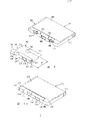
Fig. 9 represents the third embodiment of magnetic tape cassette of the present invention.Tape drum 210 comprises an outer box, and this shell has the two sides master's wall 203 that is connected by cross wall 204, and wherein a cross wall constitutes tape drum antetheca 205.Described tape drum antetheca 205 has a central openings 206, and at its two pinch roller perforate 207 and 208 is arranged respectively, and described perforate extends into relevant main wall.Main wall 203 is processed with the path 209 and 210 that the register pin path of supply equipment is used.If in equipment, then the capstan of this equipment and pinch roller all engage in the pinch roller perforate with tape drum.Described tape drum has a baffle plate 212 in addition, and this baffle plate has the main part 213 and 214 on the main wall 203 that covers shell 202, and the baffle plate antetheca 216 that extends along tape drum antetheca 205.Baffle plate antetheca 216 have central antetheca 217 with in the relative both sides of described central antetheca by preceding perforate 218 and 219 therefrom isolated side direction antethecas 220 and 221.The main part 213 of baffle plate 212 have under the off-position situation in order to close drive the aperture in the tape drum master wall cover part 222 and 223.This main part 213 also has a recess 224 in addition, drives one of aperture so that expose under the situation of open site.For exposing aperture 209 and 210, location, have path 225 and 226 in main part 213.This main part 213 comprises sweep 228 in addition, and this sweep plays the effect to the guidance component of its guidance during the baffle plate displacement.
The above-mentioned tape drum 210 that Figure 10 has represented to assemble and the baffle plate of closed condition.The no bore portion 230 of tape drum antetheca 205 is faced in the preceding perforate of baffle plate when off-position, and the no bore portion 232 of baffle plate antetheca 216 is in the face of the perforate of tape drum antetheca 205.The part 234 and 236 of tape drum antetheca 205 and main wall 203 all is respectively recessed.Baffle plate 212 just is located in these recesses, thereby the outside of baffle plate 212 is flushed with the not recess of shell 202.This main wall 203 has a recess 238 that supplies labelling to use in addition.Generally all wish to make label sizes to stay longly as far as possible.Therefore, be made into the main part of baffle plate 212 as far as possible little.This main part 214 does not extend beyond half of distance b between tape drum antetheca 205 and the tape reel center, promptly equals not extend beyond half of distance b between baffle plate antetheca 216 and recess 224 centers yet.
Another main wall 240 of Figure 11 and 12 expression tape drums 201.Figure 11 is illustrated in the baffle plate 212 of off-position, and Figure 12 is illustrated in the baffle plate 212 of open site.Also have, the main part 213 of baffle plate is located in the recess 242 of shell 202 main walls 240. Guidance part 229 and 229 is bonded in tape drum master wall 240 and the system guide groove 244.(Figure 11) covers and drives aperture 246 and 248 by covering part 222 and 223 under the off-position state, and recess 224 and path 225 and 226 and preceding perforate 218 and the 219 no bore portions in the face of tape drum shell 202.Under the state of open site (Figure 12), this recess 224 is in the face of driving aperture 248, and another drives the next door that baffle plate 212 then is located in aperture 246. Path 225 and 226 exposes aperture 250 and 252, location, also have around the main wall part 254 and 256 in aperture, location, this part 254 and 256 as be suitable for equipment 1(referring to Fig. 1) carrying plane that cooperates of register pin 11 and 12 carrying plane 13 and 14.Preceding perforate 218 in the baffle plate exposes the pinch roller perforate 207 in the shells, and another pinch roller switch 208 then is located in the baffle plate next door of open site, makes that tape 258 can be special and the tape transport equipment co-operating of equipment.In order to guarantee that baffle plate 212 has stable off-position, tape drum 201 comprises to be made baffle plate 212 (Figure 12) back into the propulsion plant 257 of off-position (Figure 11) from the open site.These propulsion plants comprise the elastic device of spring 257 forms with two spring lead-in wire 257a and 257b.Spring lead-in wire 257a plays the effect of withstanding baffle plate guidance part 228, and another spring lead-in wire 257b passes the hole 259 in the main wall 240, thereby makes itself and shell 202 relative fixed.
Figure 13 and 14 is represented baffle plate 212 front elevation of tape drum 201 under off-position and open site state respectively.Under the off-position condition (Figure 13), the no bore portion 232 of baffle plate antetheca 216 is in the face of central openings 206 and pinch roller perforate 207 and 208, and preceding perforate 218 and the 219 no bore portions 230 in the face of tape drum antetheca 205.Under the state of open site (Figure 14), preceding perforate 218 and 219 overlaps with central openings 206 and pinch roller perforate 207, thereby another pinch roller perforate 208 then is located in baffle plate 212 next doors tape 258 can be used.
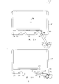
The principle of baffle plate 212 is opened in Figure 15 and 16 explanations.Sight when Figure 15 explanation is partly inserted equipment 1 with tape drum 201 by arrow 259 directions.Under the illustrated situation of Figure 15, tape drum 201 has just just contacted with propulsion plant 30 and baffle plate 212 is still in the closed position.Figure 16 explanation is slided into baffle plate 212 by propulsion plant 30 sight of open site.
Figure 17 is tape drum 201 and propulsion plant 30, baffle plate 212 this moment front elevation still in the closed position.This propulsion plant 30 has the free end portion 276 of a fork-shaped, and this part 276 partly is bonded on the tape drum master wall, and this part is located in the both sides of tape drum 201.For will be at the lateral edge 272 of the main part 213,214 of baffle plate 212,274(also referring to Figure 11 and 12) on apply a lateral pressure, described propulsion plant 30 comprises the part 264,265 that contacts with the lateral edge 272,274 of baffle plate 212.This lateral pressure that is applied on the baffle plate 212 makes baffle plate be moved to open site (Figure 16) from off-position (Figure 15).This propulsion plant 30 comprises propelling projection 264,265, and this projection constitutes the part of the propulsion plant 30 that contacts with the lateral edge 272,274 of baffle plate 212.For connecing this propelling projection 264 and 265 of sodium, the main wall 203 and 240 of tape drum is processed with recess 260 and 261, and these recesses are away from baffle plate 212 sides, and has the bevel edge 270,271 that relative tape drum antetheca 205 tilts separately.
During tape drum 201 inserted, propulsion plant 30 rotated (referring to Figure 15 and 16) around pivot 269.Suitably exposed in order to ensure perforate in the tape drum when the baffle plate open site, propulsion plant 30 promotes boundary's wall 278 that baffle plates withstand main wall 203 recesses 236.This has also stopped the noise made in coughing or vomiting noise made in coughing or vomiting of baffle plate under the condition of open site and has rung phenomenon.Required pressure is provided by spring 268.Propulsion plant moves towards pivot 269 in the baffle plate open site.Because on the position of pivot 269 propulsion plant 30, have a slit 266, might accomplish this point.Thereby this displacement makes tensioned pass through propulsion plant 30 reinforcings on baffle plate 212.Spring 268 guarantees also that when taking off tape drum propulsion plant 30 is replied position shown in Figure 15.
As proposing at the application's beginning, corresponding apparatus of the present invention also can with the compact cassette co-operating.Because compact cassette does not contain baffle plate, comprises propulsion plant so need not this device of servomechanism installation 30() as opening baffle plate.In according to equipment of the present invention, this makes that by pushing propulsion plant 30 open advancing projection 264 and 265 not contact with compact cassette reaches.For this purpose, this propulsion plant 30 comprises sensing device 32 and 33.Figure 18 is the front elevation of compact cassette 18 and propulsion plant 30.At this moment the fork-shaped free end portion 276 of propulsion plant 30 can not engage with tape drum.The sensing device 32 and 33 that is positioned at fork-shaped free end portion 276 positions is at this moment in the preceding side contacts than thickness portion 282 positions and tape drum 18.Like this, when inserting tape drum 18, just pushed propulsion plant 30 open.
Should note the embodiment shown in the present invention is not limited thereto, but within the claims scope, have a lot of other embodiment's.For example, the propulsion plant that has other structures of all kinds.For instance, the device that comprises rubber.Described propulsion plant also can save, and can make baffle plate keep motionless by means of the friction force between the projection on the tape drum master wall or baffle plate and main wall, like this, must add that some power could move this baffle plate.Baffle plate also can with non-platypelloid type tape drum (for example, have than thickness portion standard small tape drum) at antetheca perforate position together with use.
In addition, the band transmission need not to finish by capstan and pinch roller, controls the band transmission speed by control tape reel driving shaft.Under the sort of situation, can release the band transmission speed by the signal that from magnetic head assembly, produces.If like that, the tape drum antetheca only need be purchased a central openings, and the baffle plate antetheca only need comprise a central antetheca.A kind of form placed in the middle can be only to provide a capstan-pinch roller combination to be used to realize the two-way tape transmission, this combination is usually when the band transmission, provide tape transport tractive force by a direction job, and when other direction transmits tape, tape is by the tep reel drive shaft, and capstan at this moment-pinch roller combination is controlled belt speed by holding tape.In this case, the tape drum antetheca only need have a pinch roller perforate except that central openings, and, a preceding perforate only need be provided on the baffle plate antetheca.
Claims (18)
1, a kind of tape drum is equipped with tape on two coplane tape reels in its shell, this shell has the parallel main wall that the two sides is connected by cross wall, at least one main wall is provided with two and makes the drive hole that equipment tape reel driving shaft path is used, and a cross wall constitutes the tape drum antetheca with the perforate of central tape drum antetheca, with tape drum antetheca side hole in tape drum antetheca central openings both sides, this tape drum contains a single baffle plate, the certain sliding stroke distance of this baffle plate between off-position and open position is slidably, and when off-position, cover the perforate of tape drum antetheca and expose described perforate during at open position, this baffle plate can laterally slide along the tape drum antetheca, and the baffle plate antetheca that is located in close tape drum antetheca and extends in parallel along the tape drum antetheca is arranged, this baffle plate antetheca is processed with a baffle plate antetheca perforate, so that stagger just tape drum antetheca central openings and of perforate before described on the off-position baffle plate in the face of the no bore portion of tape drum antetheca, central openings is then covered at least in part by the no bore portion of baffle plate antetheca, this tape drum comprises the elastomeric spring device of promotion baffle plate to off-position, it is characterized in that
Baffle plate is positioned on the outside of tape drum,
The tape drum antetheca has the perforate of three tape drum antethecas, and baffle plate has the perforate of two baffle plate antethecas and three baffle plate antethecas are covered part,
Sliding stroke, the perforate of tape drum antetheca, the perforate of baffle plate antetheca and baffle plate antetheca are covered the size of part, whole approximately equals,
Baffle plate comprises the main part that combines and cover tape drum master wall with the baffle plate antetheca, and
Baffle plate main part and tape drum master wall comprise collaborative guidance device, are fixed in tape drum with the sliding stroke of system baffle with baffle plate.
2, tape drum as claimed in claim 1 is characterized in that,
Except the perforate of central tape drum antetheca in the two tape drum antetheca perforates at least one is a pinch roller perforate, and in order to allow to make the contact with tape in pinch roller and the tape drum, this at least one pinch roller perforate extends at least one main wall of tape drum, and
Corresponding perforate extends into the corresponding main part of baffle plate in the baffle plate, and exposes pinch roller perforate at tape drum antetheca position and two places, tape drum master wall position at open position.
3, tape drum as claimed in claim 1 is characterized in that,
The main part of baffle plate is included in off-position and covers two parts of covering that drive the aperture, and
The main part of baffle plate is processed with single corresponding aperture, and when baffle plate was shown in an open position, this perforate drove the aperture in the face of one, at this open position, makes another drive the aperture and is located in the baffle plate next door, and therefore, two drive the aperture and all exposed.
4, tape drum as claimed in claim 3 is characterized in that,
The main wall of the one side of tape drum is atresia basically, and
The main part that covers the baffle plate on the atresia master wall basically extends in half place of distance between tape drum antetheca and the tape reel center at most.
5, the tape drum described in each of front claim, wherein, the aperture, location that the main wall of the one side of tape drum has the register pin on the supply equipment to use as path, this register pin is engageable in the aperture, location, and have separately and be suitable for and be close to locating the aperture good fit carrying plane of first type surface on every side, it is characterized in that
The main part of this baffle plate has the path of its area greater than register pin carrying plane area,
When the open site, this path is superimposed upon on the aperture, location, and expose portion is around the tape drum master wall in described aperture, so as to allow between main wall and the register pin have no to hinder cooperate, and
When the off-position of baffle plate, described path is superimposed upon on the no bore portion of main wall.
6, tape drum as claimed in claim 5 is characterized in that,
The main wall of another of tape drum is processed with other aperture, location, and
Another main part of baffle plate is processed with other path.
7,, it is characterized in that only in the main part of the baffle plate of the same side, providing the path of using for register pin with that face master wall with driving aperture as claim 3 or 4 described tape drums.
8, the tape drum described in each of front claim, it is characterized in that, the collaborative guidance device of baffle plate main part and the main wall of tape drum are such arrangements, making baffle plate is movably from its off-position to two reverse directions along the tape drum antetheca, and baffle plate has two open sites that are provided with symmetrically in the relative both sides of off-position.
9, the tape drum described in each of front claim is characterized in that,
The main wall of tape drum has a system guide groove that is used for making baffle, and
This baffle plate comprise horizontal expansion on the main part and with the guidance part of this system guide groove engagement.
10, the tape drum described in each of front claim, it is characterized in that making main wall and tape drum antetheca recessed partly in the distance that is substantially equal to baffle plate thickness at least in following this mode, that is, make the not concave portion of described wall and the outside surface of baffle plate keep each other basically flushing.
11, tape drum as claimed in claim 1 is characterized in that,
Spring assembly between tape drum master wall and baffle plate main part, and
This spring assembly is covered by the baffle plate protection in any position of baffle plate.
12, tape drum as claimed in claim 11 is characterized in that,
This spring assembly comprises a spring that two lead-in wires are arranged,
This spring is arranged in the recess of tape drum master wall,
The baffle plate main part comprises a mate perpendicular to the main part extension, and
Lead-in wire of spring is meshed with the mate on the baffle plate, and another lead-in wire and the engagement of tape drum master wall.
13, the tape drum described in each of front claim is characterized in that,
At the lateral edge place of baffle plate, tep reel has a recess that is used for admitting that part of propulsion plant that contacts with the lateral edge of baffle plate on main wall.
14, a kind of and the crew-served equipment of tape drum, this tape drum is equipped with tape on two coplane tape reels in its shell, this shell has the parallel main wall that the two sides is connected by cross wall, at least one main wall is provided with two and makes the drive hole that equipment tape reel driving shaft path is used, and a cross wall constitutes the tape drum antetheca with the perforate of central tape drum antetheca, with tape drum antetheca side hole two of tape drum antetheca central openings, this tape drum contains a single baffle plate, the certain sliding stroke distance of this baffle plate between off-position and open position is slidably, and when off-position, cover the perforate of tape drum antetheca and expose described perforate during at open position, this baffle plate can laterally slide along the tape drum antetheca, and the baffle plate antetheca that is located in close tape drum antetheca and extends in parallel along the tape drum antetheca is arranged, this baffle plate antetheca is processed with a baffle plate antetheca perforate, so that stagger just tape drum antetheca central openings and of perforate before described on the off-position baffle plate in the face of the no bore portion of tape drum antetheca, central openings is then covered at least in part by the no bore portion of baffle plate antetheca, this tape drum comprises the elastomeric spring device of promotion baffle plate to off-position, and
Baffle plate is positioned on the outside of tape drum,
The tape drum antetheca has the perforate of three tape drum antethecas, and baffle plate has the perforate of two baffle plate antethecas and three baffle plate antethecas are covered part,
Sliding stroke, the perforate of tape drum antetheca, the perforate of baffle plate antetheca and baffle plate antetheca are covered the size of part, whole approximately equals,
Baffle plate comprises the main part that combines and cover tape drum master wall with the baffle plate antetheca, and
Baffle plate main part and tape drum master wall comprise collaborative guidance device, are fixed in tape drum with the sliding stroke of system baffle with baffle plate,
It is characterized in that,
This equipment comprises in order to apply lateral pressure so that open the propulsion plant of baffle plate on the lateral edge of tape drum baffle plate main part.
15, equipment as claimed in claim 14 is characterized in that this propulsion plant comprises at least and is fork-shaped basically around the free end portion that engages the tep reel antetheca, and it also comprises and is used for and the crew-served propelling projection of baffle plate.
16, as claim 14 or 15 described equipment, it is characterized in that propulsion plant is processed with a groove, a pivot extends by this groove, so that this propulsion plant is can be around one pivotally supported, but also can be towards the slippage of pivot direction.
17, tape drum as claimed in claim 13 is characterized in that the chamfered portion that the groove in distance baffle plate distally has a relative tape drum antetheca to tilt.
18, tape drum as claimed in claim 13, it is characterized in that, be applicable to the another kind of tape drum of acceptance in order to adapt to this equipment, this tape drum is not baffled and a highly higher antetheca arranged, propulsion plant comprises transducing part, this transducing part during another kind of tape drum inserts with the antetheca co-operating slidably of tape drum.
Applications Claiming Priority (4)
| Application Number | Priority Date | Filing Date | Title |
|---|---|---|---|
| NL8901682 | 1989-07-03 | ||
| NL8901682A NL8901682A (en) | 1989-07-03 | 1989-07-03 | System for recording-reproducing signals on-from magnetic tape - has shutter which is slidable between open and closed positions, used to cover openings in cassette |
| NL9000348 | 1990-02-14 | ||
| NL9000348A NL9000348A (en) | 1990-02-14 | 1990-02-14 | System for recording-reproducing signals on-from magnetic tape - has shutter which is slidable between open and closed positions, used to cover openings in cassette |
Publications (2)
| Publication Number | Publication Date |
|---|---|
| CN1048621A CN1048621A (en) | 1991-01-16 |
| CN1027403C true CN1027403C (en) | 1995-01-11 |
Family
ID=26646549
Family Applications (1)
| Application Number | Title | Priority Date | Filing Date |
|---|---|---|---|
| CN90103372A Expired - Fee Related CN1027403C (en) | 1989-07-03 | 1990-06-30 | Tape signal recording and playback system and its equipment and cassettes |
Country Status (20)
| Country | Link |
|---|---|
| EP (1) | EP0406943B1 (en) |
| JP (1) | JPH0344857A (en) |
| KR (1) | KR910003621A (en) |
| CN (1) | CN1027403C (en) |
| AR (1) | AR246005A1 (en) |
| AT (1) | ATE138217T1 (en) |
| AU (1) | AU647394B2 (en) |
| BR (1) | BR9003124A (en) |
| CA (1) | CA2020214A1 (en) |
| CS (1) | CS568690A3 (en) |
| CZ (1) | CZ325990A3 (en) |
| DE (1) | DE69026984T2 (en) |
| ES (1) | ES2088407T3 (en) |
| FI (1) | FI903302A7 (en) |
| HU (1) | HU210700B (en) |
| MY (1) | MY105952A (en) |
| PL (1) | PL164899B1 (en) |
| PT (1) | PT94570A (en) |
| RU (1) | RU2066482C1 (en) |
| YU (2) | YU123090A (en) |
Families Citing this family (29)
| Publication number | Priority date | Publication date | Assignee | Title |
|---|---|---|---|---|
| US5161079A (en) * | 1990-01-19 | 1992-11-03 | Matsushita Electric Industrial Co., Ltd. | Tape cassette with slidable shutter |
| JP2630004B2 (en) * | 1990-02-26 | 1997-07-16 | 松下電器産業株式会社 | Tape cassette mounting device |
| AT394789B (en) * | 1990-10-11 | 1992-06-25 | Philips Nv | CASSETTE FOR A RECORDING CARRIER |
| DE69120494T2 (en) * | 1990-10-11 | 1997-01-23 | Philips Electronics Nv | Cassette with magnetic tape |
| JPH04254950A (en) * | 1991-02-05 | 1992-09-10 | Matsushita Electric Ind Co Ltd | Tape recorder |
| NL9100222A (en) * | 1991-02-08 | 1992-09-01 | Philips Nv | DEVICE FOR COOPERATION WITH A CASSETTE. |
| JPH04274071A (en) * | 1991-02-28 | 1992-09-30 | Victor Co Of Japan Ltd | Magnetic tape cassette |
| EP0514979A3 (en) * | 1991-05-20 | 1993-12-01 | Philips Nv | Cassette tape recorder |
| DE4116920A1 (en) * | 1991-05-24 | 1992-11-26 | Philips Patentverwaltung | ARRANGEMENT CONSTRUCTING A MAGNETIC TAPE CASSETTE DEVICE WITH A DRIVE AND WITH LOADING MECHANISM FOR MAGNETIC TAPE CASSETTES AND A MAGNETIC TAPE CASSETTE |
| US5406430A (en) * | 1991-08-29 | 1995-04-11 | Matsushita Electric Industrial Co., Ltd. | Cassette tape mount for use in a cassette tape recorder |
| EP0530700A2 (en) * | 1991-08-30 | 1993-03-10 | Matsushita Electric Industrial Co., Ltd. | A cassette tape mount for use in a cassette tape recorder |
| JP2595156B2 (en) * | 1991-12-13 | 1997-03-26 | シャープ株式会社 | Recording and playback device |
| JPH05182313A (en) * | 1991-12-27 | 1993-07-23 | Matsushita Electric Ind Co Ltd | Tape recorder |
| JPH05182290A (en) * | 1991-12-27 | 1993-07-23 | Matsushita Electric Ind Co Ltd | Tape type detector |
| DE4202334A1 (en) * | 1992-01-29 | 1993-08-05 | Basf Magnetics Gmbh | CASSETTE WITH RECORD CARRIER |
| CA2088397A1 (en) * | 1992-02-03 | 1993-08-04 | Masaru Watanabe | Tape cassette |
| DE9201957U1 (en) * | 1992-02-15 | 1992-04-16 | BASF Magnetics GmbH, 6800 Mannheim | Cassette with recording medium |
| JP2758304B2 (en) * | 1992-02-28 | 1998-05-28 | シャープ株式会社 | Cassette tape device for heterogeneous cassette tapes |
| TW211617B (en) * | 1992-05-26 | 1993-08-21 | Philips Electronics Nv | System for recording and/or reproducing signals, and reset cassette suitable for use in the system |
| AT397738B (en) * | 1992-05-27 | 1994-06-27 | Philips Nv | RECORDING AND / OR PLAYING DEVICE FOR A CASSETTE CONTAINING A RECORDING CARRIER |
| AT397735B (en) * | 1992-07-07 | 1994-06-27 | Philips Nv | RECORDING AND / OR PLAYING DEVICE FOR A MAGNETIC TAPE CASSETTE |
| TW235361B (en) * | 1992-11-13 | 1994-12-01 | Philips Electronics Nv | |
| DE9301652U1 (en) * | 1993-02-06 | 1993-04-01 | BASF Magnetics GmbH, 6800 Mannheim | Cassette, in particular magnetic tape cassette, with a housing |
| US5404073A (en) * | 1993-11-12 | 1995-04-04 | Chunghwa Picture Tubes, Ltd. | Antiglare/antistatic coating for CRT |
| EP0722605A1 (en) * | 1994-06-23 | 1996-07-24 | Koninklijke Philips Electronics N.V. | Apparatus for cooperation with an information carrier in a cassette |
| BE1009341A3 (en) * | 1995-04-05 | 1997-02-04 | Staar Sa | Detection device type of tapes. |
| WO1998033324A2 (en) * | 1997-01-27 | 1998-07-30 | Koninklijke Philips Electronics N.V. | Embedding supplemental data in an encoded signal |
| WO1999003791A1 (en) | 1997-07-16 | 1999-01-28 | Nippon Electric Glass Co., Ltd. | Glass article having surface coating of boric acid and method for producing the same |
| JP3658516B2 (en) * | 1998-03-16 | 2005-06-08 | 日立マクセル株式会社 | Cartridge for recording medium |
Family Cites Families (10)
| Publication number | Priority date | Publication date | Assignee | Title |
|---|---|---|---|---|
| GB712536A (en) * | 1951-10-24 | 1954-07-28 | Emi Ltd | Improvements in or relating to magnetic transducing apparatus |
| JPS5041880Y1 (en) * | 1970-01-24 | 1975-11-28 | ||
| US3706979A (en) * | 1971-04-23 | 1972-12-19 | Ibm | Cassette driven by either vacuum bins or pinch rollers |
| FR2176238A5 (en) * | 1972-03-15 | 1973-10-26 | Sfim | |
| NL8102877A (en) * | 1981-06-16 | 1983-01-17 | Philips Nv | MAGNETIC TAPE CASSETTE. |
| US4620254A (en) * | 1983-01-04 | 1986-10-28 | Bsr North America, Ltd. | Information storage and retrieval system including a tape cartridge having a slidable cover |
| JPS6051682U (en) * | 1983-09-16 | 1985-04-11 | 富士写真フイルム株式会社 | magnetic tape cassette |
| US4614270A (en) * | 1983-09-16 | 1986-09-30 | Fuji Photo Film Co., Ltd. | Magnetic tape cassette |
| KR880002806Y1 (en) * | 1985-07-18 | 1988-07-30 | 주식회사 금성사 | Cassette protective cover opening of video tape recorder |
| US4896237A (en) * | 1985-08-30 | 1990-01-23 | Sony Corporation | Magnetic tape cartridge compatible with disk drive and tape drive mechanism therefor |
-
1990
- 1990-06-22 YU YU123090A patent/YU123090A/en unknown
- 1990-06-27 EP EP90201699A patent/EP0406943B1/en not_active Expired - Lifetime
- 1990-06-27 ES ES90201699T patent/ES2088407T3/en not_active Expired - Lifetime
- 1990-06-27 AT AT90201699T patent/ATE138217T1/en not_active IP Right Cessation
- 1990-06-27 DE DE69026984T patent/DE69026984T2/en not_active Expired - Fee Related
- 1990-06-28 AR AR90317258A patent/AR246005A1/en active
- 1990-06-29 CZ CS903259A patent/CZ325990A3/en unknown
- 1990-06-29 CA CA002020214A patent/CA2020214A1/en not_active Abandoned
- 1990-06-29 FI FI903302A patent/FI903302A7/en not_active IP Right Cessation
- 1990-06-29 RU SU904830354A patent/RU2066482C1/en active
- 1990-06-29 HU HU904045A patent/HU210700B/en not_active IP Right Cessation
- 1990-06-30 CN CN90103372A patent/CN1027403C/en not_active Expired - Fee Related
- 1990-06-30 MY MYPI90001114A patent/MY105952A/en unknown
- 1990-07-02 YU YU128190A patent/YU128190A/en unknown
- 1990-07-02 PL PL90285903A patent/PL164899B1/en unknown
- 1990-07-02 PT PT94570A patent/PT94570A/en not_active Application Discontinuation
- 1990-07-02 AU AU58017/90A patent/AU647394B2/en not_active Ceased
- 1990-07-03 KR KR1019900009991A patent/KR910003621A/en not_active Abandoned
- 1990-07-03 BR BR909003124A patent/BR9003124A/en unknown
- 1990-07-03 JP JP2177693A patent/JPH0344857A/en active Pending
- 1990-11-16 CS CS905686A patent/CS568690A3/en unknown
Also Published As
| Publication number | Publication date |
|---|---|
| KR910003621A (en) | 1991-02-28 |
| HUT58424A (en) | 1992-02-28 |
| YU123090A (en) | 1994-04-05 |
| MY105952A (en) | 1995-02-28 |
| CZ325990A3 (en) | 1994-10-19 |
| ATE138217T1 (en) | 1996-06-15 |
| JPH0344857A (en) | 1991-02-26 |
| PT94570A (en) | 1992-03-31 |
| CS568690A3 (en) | 1992-05-13 |
| FI903302A7 (en) | 1991-01-04 |
| EP0406943B1 (en) | 1996-05-15 |
| AR246005A1 (en) | 1994-03-30 |
| EP0406943A1 (en) | 1991-01-09 |
| RU2066482C1 (en) | 1996-09-10 |
| AU5801790A (en) | 1991-01-03 |
| ES2088407T3 (en) | 1996-08-16 |
| DE69026984D1 (en) | 1996-06-20 |
| HU210700B (en) | 1995-06-28 |
| YU128190A (en) | 1994-04-05 |
| HU904045D0 (en) | 1990-12-28 |
| AU647394B2 (en) | 1994-03-24 |
| PL285903A1 (en) | 1991-03-11 |
| DE69026984T2 (en) | 1996-11-28 |
| PL164899B1 (en) | 1994-10-31 |
| CN1048621A (en) | 1991-01-16 |
| CA2020214A1 (en) | 1991-01-04 |
| FI903302A0 (en) | 1990-06-29 |
| BR9003124A (en) | 1991-08-27 |
Similar Documents
| Publication | Publication Date | Title |
|---|---|---|
| CN1027403C (en) | Tape signal recording and playback system and its equipment and cassettes | |
| SU1565357A3 (en) | Tape cassette | |
| AU668985B2 (en) | Arcuate scanning tape drive | |
| US8027122B2 (en) | Dual sided tape storage device and dual sided tape drive | |
| CN1026835C (en) | Longitudinal magnetic tape recording system, magnetic tape apparatus for use in the system, and magnetic head for use in the magnatic tape apparatus | |
| EP0082014A1 (en) | Tape cassette adapter | |
| EP0929071B1 (en) | Multiple tape cartridge and drive system wherein tapes are extracted from the cartridge | |
| EP0229996B1 (en) | System for recording, storing and reading information signals on a record medium | |
| KR900008494B1 (en) | Tape Loading Device | |
| EP0356184B1 (en) | Tape-loading mechanism for a magnetic recording/reproducing apparatus for selective use of tape cassettes of two different sizes | |
| EP0576083A2 (en) | Magnetic-tape apparatus comprising a pressure-roller device | |
| JPH05182313A (en) | Tape recorder | |
| RU2027229C1 (en) | System, equipment and cassette for recording and/or playback of signals to/from magnetic tape | |
| KR0179247B1 (en) | Pinch roller device of video equipment | |
| MY126291A (en) | Method for recording data onto tape-shaped recording media for high-speed retrieval based on system log information recorded in a leading partition | |
| EP0557726B1 (en) | Cassette tape player compatible with cassette tapes of different formats | |
| GB2096572A (en) | Tape cassettes and cassette type tape recorders | |
| US5258881A (en) | Tape cassette loading system in recording and/or reproducing apparatus | |
| CA2009464C (en) | Loading mechanism for a recording and producing apparatus | |
| KR860000920B1 (en) | Arm conveying apparatus in recording disk reproducing apparatus | |
| JP2636828B2 (en) | Tape cassette | |
| US5237479A (en) | Tape cassette with slidable cover | |
| US7427043B2 (en) | Tape cartridge with multiple keying features | |
| JPH0467710B2 (en) | ||
| JPS60111537U (en) | cassette tape recorder |
Legal Events
| Date | Code | Title | Description |
|---|---|---|---|
| C06 | Publication | ||
| PB01 | Publication | ||
| C10 | Entry into substantive examination | ||
| SE01 | Entry into force of request for substantive examination | ||
| C14 | Grant of patent or utility model | ||
| GR01 | Patent grant | ||
| C53 | Correction of patent of invention or patent application | ||
| COR | Change of bibliographic data |
Free format text: CORRECT: PATENTEE; FROM: N.V. PHILIPS OPTICAL LAMP MANUFACTURING COMPANY TO: N.V. PHILIPS OPTICALLAMP LTD., CO. |
|
| CP01 | Change in the name or title of a patent holder |
Patentee after: Philips Electronics N. V. Patentee before: N.V. Philips' Gloeipenfabrieken |
|
| C53 | Correction of patent of invention or patent application | ||
| COR | Change of bibliographic data |
Free format text: CORRECT: PATENTEE; FROM: N.V. PHILIPS OPTICAL LAMP LTD., CO. TO: ROYAL PHILIPS ELECTRONICS CO., LTD. |
|
| CP01 | Change in the name or title of a patent holder |
Patentee after: Koninklike Philips Electronics N. V. Patentee before: Philips Electronics N. V. |
|
| C19 | Lapse of patent right due to non-payment of the annual fee | ||
| CF01 | Termination of patent right due to non-payment of annual fee |