CN102748191A - Integrated through-flow water turbine generator set - Google Patents
Integrated through-flow water turbine generator set Download PDFInfo
- Publication number
- CN102748191A CN102748191A CN2012102120579A CN201210212057A CN102748191A CN 102748191 A CN102748191 A CN 102748191A CN 2012102120579 A CN2012102120579 A CN 2012102120579A CN 201210212057 A CN201210212057 A CN 201210212057A CN 102748191 A CN102748191 A CN 102748191A
- Authority
- CN
- China
- Prior art keywords
- generator
- shell
- water turbine
- rotating shaft
- runner
- Prior art date
- Legal status (The legal status is an assumption and is not a legal conclusion. Google has not performed a legal analysis and makes no representation as to the accuracy of the status listed.)
- Pending
Links
- XLYOFNOQVPJJNP-UHFFFAOYSA-N water Substances O XLYOFNOQVPJJNP-UHFFFAOYSA-N 0.000 title claims abstract description 34
- 230000008878 coupling Effects 0.000 claims description 6
- 238000010168 coupling process Methods 0.000 claims description 6
- 238000005859 coupling reaction Methods 0.000 claims description 6
- 230000005484 gravity Effects 0.000 claims description 2
- 239000000463 material Substances 0.000 abstract description 2
- 238000010248 power generation Methods 0.000 abstract 1
- 230000005611 electricity Effects 0.000 description 6
- 238000012545 processing Methods 0.000 description 4
- 238000004804 winding Methods 0.000 description 4
- 238000007667 floating Methods 0.000 description 3
- 238000000034 method Methods 0.000 description 3
- 230000009286 beneficial effect Effects 0.000 description 2
- 238000009434 installation Methods 0.000 description 2
- 238000007789 sealing Methods 0.000 description 2
- 239000003245 coal Substances 0.000 description 1
- 238000011161 development Methods 0.000 description 1
- 238000005516 engineering process Methods 0.000 description 1
- 230000007613 environmental effect Effects 0.000 description 1
- 230000006698 induction Effects 0.000 description 1
- 238000012423 maintenance Methods 0.000 description 1
- 238000007634 remodeling Methods 0.000 description 1
- 230000006641 stabilisation Effects 0.000 description 1
- 238000011105 stabilization Methods 0.000 description 1
Images



Classifications
-
- Y—GENERAL TAGGING OF NEW TECHNOLOGICAL DEVELOPMENTS; GENERAL TAGGING OF CROSS-SECTIONAL TECHNOLOGIES SPANNING OVER SEVERAL SECTIONS OF THE IPC; TECHNICAL SUBJECTS COVERED BY FORMER USPC CROSS-REFERENCE ART COLLECTIONS [XRACs] AND DIGESTS
- Y02—TECHNOLOGIES OR APPLICATIONS FOR MITIGATION OR ADAPTATION AGAINST CLIMATE CHANGE
- Y02E—REDUCTION OF GREENHOUSE GAS [GHG] EMISSIONS, RELATED TO ENERGY GENERATION, TRANSMISSION OR DISTRIBUTION
- Y02E10/00—Energy generation through renewable energy sources
- Y02E10/20—Hydro energy
Landscapes
- Other Liquid Machine Or Engine Such As Wave Power Use (AREA)
- Connection Of Motors, Electrical Generators, Mechanical Devices, And The Like (AREA)
Abstract
The invention provides an integrated through-flow water turbine generator set, which comprises a water turbine, a generator, a water inlet pipe component, a water outlet pipe component, a generator shell component and a water turbine rotor block, wherein the water inlet pipe component and the water outlet pipe component are connected with the water turbine; the water turbine and the generator set have an integrated structure; the water turbine rotor block is arranged in the generator shell component; the generator shell component comprises a shell and connecting pieces at the two ends of the shell; and the shell is hermetically connected with the water turbine rotor block through the connecting pieces. The water turbine rotor block comprises blades, and a rotating shaft and a rotating wheel which are fixedly connected on both inner and outer sides of the blades; the rotating shaft is movably connected with the generator shell component; and relative motion is produced through a bearing in a bearing chamber on the shell component and the shell. A plurality of groups of blades can be arranged, so that a structural form that a plurality of blade sets are arranged in the direction of the rotating shaft is formed, and the overall hydraulic energy utilization efficiency is increased to the greatest extent. The integrated through-flow water turbine generator set has the advantages of light dead weight, less material consumption, small resistance to hydraulic energy and less consumption and high power generation efficiency.
Description
Technical field
The present invention relates to a kind of integrated tubular-turbine generator group of supplying power based on the civilian little load of small-sized waterfall, river, lake, reservoir or water supply line.
Background technique
Because of day by day exhaustion, the increase of environmental protection pressure and the pressing for of sustainable development of traditional coal, oil equal energy source, generation of electricity by new energy becomes the focus that countries in the world are paid close attention to.Wherein, water can have characteristics such as regenerability is good, no secondary pollution, makes hydroelectric power receive much concern.
Integrated tubular-turbine generator group is the key equipment in the hydroelectric power system, and it can be converted into water mechanical energy and then be converted into electric energy.At present, hydroelectric generator mainly contains two types of the integrated tubular-turbine generator group of axial flow and tubular integral tubular-turbine generator groups.The axial-flow wheel power generating equipment exists complex structure, build huge, installation, maintenance inconvenience, shortcomings such as mechanical efficiency is low, operating cost height.
Summary of the invention
The technical problem that the present invention will solve is exactly not enough to existing in prior technology, and provides a kind of waterpower utilization rate high integrated tubular-turbine generator group.
This programme is realized through following technical measures: a kind of integrated tubular-turbine generator group, and it comprises water turbine and generator, and the intake pipe assembly, the outlet pipe component that are connected with water turbine, said water turbine and generator set are integrated; The hydraulic generator unit comprise the generator casing assembly be installed in its inner hydroturbine rotor body, said generator casing assembly comprises the coupling at shell and shell two ends, shell and hydroturbine rotor body are tightly connected through coupling; The inwall of said shell evenly is processed with deep hole, and the magnetic pole of the stator of generator is installed in the deep hole, is wound with coil on the magnetic pole of the stator; Said hydroturbine rotor body comprises runner and rotating shaft, is fixed with some suite face blades between runner and the rotating shaft.
Said rotating shaft is level or inclination rotating shaft, and its two ends flexibly connect through bearing and motor housing assembly.
Said runner is coaxial with rotating shaft, and runner is isometrical cylindrical structure, and leaves the free gap between this runner and the generator casing assembly.
Be processed with some annular grooves on the said runner outer wall, the rotor magnetic pole in the generator is installed in the annular groove.
Said intake pipe assembly comprises fence and drain pipe assembly, and intake pipe is pre-large post-small horn mouth structure.Be connected with drain pipe in the intake pipe assembly, inner valve and the outer end connection dredge pump of connecting of drain pipe, this also is the necessary condition that produces negative pressure.
Said fence is gravity or negative pressure return structure.
Said outlet pipe is pre-small post-large horn mouth structure.
Beneficial effect of the present invention can draw from foregoing description; Because above-mentioned water turbine and generator are integrated; Intake pipe assembly and outlet pipe are separable structure, and drain pipe is inner in the intake pipe assembly connects valve, and the outer end connects the necessary condition that dredge pump is the generation negative pressure.Above-mentioned water turbine comprises blade and the rotating shaft and the runner that are fixedly connected with the inside and outside both sides of blade, and rotating shaft and generator casing assembly flexibly connect, and produce relative movement through bearing in the bearing chamber on the casing assembly and shell.This movable connection structure is realized through following mode: be connected floating bearing and thrust-bearing respectively with the rotating shaft two ends; Floating bearing can radial location, can guarantee the rotation of whole rotor body again; Simultaneously, thrust-bearing can carry out axial location to rotor body, guarantees the job stabilization of rotor body; The bearing chamber sealing configuration can be protected the sealing of bearing again and lubricate, thereby has guaranteed the operation and the replacement cycle of bearing, and bearing is able to ensure working life.
Rotor magnetic pole in the above-mentioned generator set is installed in the processing groove of runner outer wall of rotor body; Magnetic pole of the stator is installed in the deep hole processing on the inwall of generator casing and is corresponding with rotor magnetic pole position; Make magnetic pole of the stator equal and corresponding up and down with the external diameter air gap of rotor magnetic pole place circle; Rotor body drives rotor magnetic pole and rotates synchronously, and stator cutting rotor magnetic field produces induction electromotive force and generates electricity.Stator and rotor are the module combinations structure in this generator set, and winding is concentric winding, but each module independent operating also can the polylith combined running.This generator has short magnetic circuit, modularization, easy for installation, characteristics that efficient is high, and can safe operation in extreme climate environment.
Above-mentioned generator casing assembly is the shell of stator, and the coupling that is connected with shell is again the support of rotor body, and the integrity of stator and rotor body is able to embody, and has guaranteed the intensity and the stability of generator.Direction along above-mentioned rotating shaft can be provided with many group blades, and the concrete quantity of blade can be provided with according to integrated tubular-turbine generator group specification flexibly; And blade is evenly arranged.Many group blades are formed on a plurality of water wheels structural types of rotor shaft direction; The blade of anteposition utilizes the water of high pressure to generate electricity; The blade of meta utilizes surplus water to generate electricity; The negative pressure that the blade of position, back utilizes outlet pipe to produce is generated electricity, and can the water of diverse location can all be made full use of, and having improved whole water to greatest extent can utilization ratio.
Above-mentioned blade is a surface-shaped structure, to increase the area of whole blade, improves the utilization ratio of water ability.Respectively organize in addition blade with one heart radial be uniformly distributed with arrangements, each organize between the position stagger each other.Blade this as flake structure, himself weight is lighter, consumptive material is few, and to water can consumption also little.This shows that the present invention compared with prior art has outstanding substantive distinguishing features and obvious improvement, the beneficial effect of its enforcement also is conspicuous.
Description of drawings
Fig. 1 is a sectional structure schematic representation of the present invention.
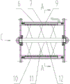
Fig. 2 is for removing the hydraulic generator unit body figure of intake pipe assembly and outlet pipe among Fig. 1.
Fig. 3 is an A-A sectional structure schematic representation among Fig. 2.
Fig. 4 be among Fig. 1 B to view.
Fig. 5 be among Fig. 2 C to view.
Among the figure, 1 is intake pipe, and 2 is fence, and 3 is drain pipe, and 4 is valve, and 5 is bearing chamber, and 6 is shell, and 7 is magnetic pole of the stator, and 8 is coil, and 9 is magnet, and 10 is runner, and 11 is blade, and 12 are rotating shaft, and 13 is binding tube, and 14 is outlet pipe.
Embodiment
For clearly demonstrating the technical characterstic of this programme, below through embodiment, and combine its accompanying drawing, this programme is set forth.
Embodiment: like Fig. 1-shown in Figure 5: a kind of integrated tubular-turbine generator group; It comprises water turbine and generator; And the intake pipe assembly 1 that is connected with water turbine, outlet pipe component 14; The hydraulic generator unit comprises the generator casing assembly and is installed in its inner hydroturbine rotor body that said generator casing assembly comprises the coupling at shell 6 and shell 6 two ends.Said hydroturbine rotor body comprises runner 10 and rotating shaft 12, is fixed with some suite face blades 11 between runner 10 and the rotating shaft 12.Said rotating shaft 12 is a horizontal rotating shaft, and shell 6 is tightly connected through floating bearing and the thrust-bearing that is arranged in the bearing chamber 5 with rotating shaft 12.Runner 10 is coaxial with rotating shaft 12, and runner 10 is isometrical cylindrical structure, and leaves the free gap between runner 10 and the generator casing assembly.Be processed with some annular grooves on said runner 10 outer walls, the rotor magnetic pole in the generator is installed in the annular groove, promptly magnet 9.The inwall of said shell 6 evenly is processed with deep hole, and the magnetic pole of the stator 7 of generator is installed in the deep hole, is wound with coil 8 on the magnetic pole of the stator 7.Said intake pipe assembly comprises intake pipe 1, fence 2 and drain pipe.Be connected with drain pipe 3 in the intake pipe assembly, drain pipe 3 inner valve 4 and the outer end connection dredge pumps of connecting.Wherein fence 2 is a negative pressure return structure.Outlet pipe 14 is pre-small post-large horn mouth structure, and intake pipe 1 is pre-large post-small horn mouth structure.
Electricity generating principle process of the present invention is: the hydroturbine rotor body that current are formed through runner 10, blade 11 and rotating shaft 12 makes blade drive runner 10 and rotates.Magnet 9 rotates with runner synchronously, and magnetic field is produced field current by the stator cutting by belt coil 8, and mechanical energy is converted into electric energy, and electric energy exports in the control cabinet and transforms via binding tube 13 through coil and stores.
Can pass through existing techniques in realizing without the technical characteristics of describing among the present invention, repeat no more at this.The present invention is not limited in above-mentioned embodiment, and the variation that those of ordinary skills make in essential scope of the present invention, remodeling, interpolation or replacement also should belong to protection scope of the present invention.
Claims (7)
1. integrated tubular-turbine generator group, it comprises water turbine and generator, and the intake pipe assembly, the outlet pipe component that are connected with water turbine, it is characterized in that: said water turbine and generator set are integrated; The hydraulic generator unit comprise the generator casing assembly be installed in its inner hydroturbine rotor body, said generator casing assembly comprises the coupling at shell and shell two ends, shell and hydroturbine rotor body are tightly connected through coupling; The inwall of said shell evenly is processed with deep hole, and the magnetic pole of the stator of generator is installed in the deep hole, is wound with coil on the magnetic pole of the stator; Said hydroturbine rotor body comprises runner and rotating shaft, is fixed with some suite face blades between runner and the rotating shaft.
2. integrated tubular-turbine generator group according to claim 1, it is characterized in that: said runner is coaxial with rotating shaft, and runner is isometrical cylindrical structure, and leaves the free gap between this runner and the generator casing assembly.
3. integrated tubular-turbine generator group according to claim 2 is characterized in that: said rotating shaft is level or inclination rotating shaft, and its two ends flexibly connect through bearing and motor housing assembly.
4. integrated tubular-turbine generator group according to claim 2 is characterized in that: be processed with some annular grooves on the said runner outer wall, the rotor magnetic pole in the generator is installed in the annular groove.
5. integrated tubular-turbine generator group according to claim 1 is characterized in that: said intake pipe assembly comprises fence and drain pipe assembly, and intake pipe is pre-large post-small horn mouth structure.
6. integrated tubular-turbine generator group according to claim 1 is characterized in that: said fence is gravity or negative pressure return structure.
7. integrated tubular-turbine generator group according to claim 1 is characterized in that: said outlet pipe is pre-small post-large horn mouth structure.
Priority Applications (1)
| Application Number | Priority Date | Filing Date | Title |
|---|---|---|---|
| CN2012102120579A CN102748191A (en) | 2012-06-26 | 2012-06-26 | Integrated through-flow water turbine generator set |
Applications Claiming Priority (1)
| Application Number | Priority Date | Filing Date | Title |
|---|---|---|---|
| CN2012102120579A CN102748191A (en) | 2012-06-26 | 2012-06-26 | Integrated through-flow water turbine generator set |
Publications (1)
| Publication Number | Publication Date |
|---|---|
| CN102748191A true CN102748191A (en) | 2012-10-24 |
Family
ID=47028621
Family Applications (1)
| Application Number | Title | Priority Date | Filing Date |
|---|---|---|---|
| CN2012102120579A Pending CN102748191A (en) | 2012-06-26 | 2012-06-26 | Integrated through-flow water turbine generator set |
Country Status (1)
| Country | Link |
|---|---|
| CN (1) | CN102748191A (en) |
Cited By (3)
| Publication number | Priority date | Publication date | Assignee | Title |
|---|---|---|---|---|
| CN103206332B (en) * | 2013-04-01 | 2015-08-12 | 武汉理工大学 | A kind of tubular turbine automatic cleaning apparatus |
| CN105207401A (en) * | 2015-09-09 | 2015-12-30 | 刘运念 | Combined generator |
| CN112072858A (en) * | 2020-08-24 | 2020-12-11 | 银川威力传动技术股份有限公司 | Gate pump direct-drive permanent magnet motor |
Citations (5)
| Publication number | Priority date | Publication date | Assignee | Title |
|---|---|---|---|---|
| US20050002783A1 (en) * | 2003-04-16 | 2005-01-06 | Clement Hiel | Diffuser-augmented wind turbine |
| CN1858434A (en) * | 2005-05-02 | 2006-11-08 | 刘成江 | Submerging type axial through flow hydropower generator |
| CN101676552A (en) * | 2008-09-16 | 2010-03-24 | 蒋明兴 | Siphon hydroelectric generator group |
| CN201902282U (en) * | 2010-11-10 | 2011-07-20 | 赵国豪 | Water flow type generator |
| CN201991679U (en) * | 2011-02-21 | 2011-09-28 | 冯岩 | Electromagnetic power generator for pipeline |
-
2012
- 2012-06-26 CN CN2012102120579A patent/CN102748191A/en active Pending
Patent Citations (5)
| Publication number | Priority date | Publication date | Assignee | Title |
|---|---|---|---|---|
| US20050002783A1 (en) * | 2003-04-16 | 2005-01-06 | Clement Hiel | Diffuser-augmented wind turbine |
| CN1858434A (en) * | 2005-05-02 | 2006-11-08 | 刘成江 | Submerging type axial through flow hydropower generator |
| CN101676552A (en) * | 2008-09-16 | 2010-03-24 | 蒋明兴 | Siphon hydroelectric generator group |
| CN201902282U (en) * | 2010-11-10 | 2011-07-20 | 赵国豪 | Water flow type generator |
| CN201991679U (en) * | 2011-02-21 | 2011-09-28 | 冯岩 | Electromagnetic power generator for pipeline |
Cited By (3)
| Publication number | Priority date | Publication date | Assignee | Title |
|---|---|---|---|---|
| CN103206332B (en) * | 2013-04-01 | 2015-08-12 | 武汉理工大学 | A kind of tubular turbine automatic cleaning apparatus |
| CN105207401A (en) * | 2015-09-09 | 2015-12-30 | 刘运念 | Combined generator |
| CN112072858A (en) * | 2020-08-24 | 2020-12-11 | 银川威力传动技术股份有限公司 | Gate pump direct-drive permanent magnet motor |
Similar Documents
| Publication | Publication Date | Title |
|---|---|---|
| US8080913B2 (en) | Hollow turbine | |
| CN103397974B (en) | Magnetic levitation hydro-generator | |
| CN104595094B (en) | hydraulic turbine generator | |
| CN104204509A (en) | Water turbine | |
| US20120207588A1 (en) | Portable Hydro Electric Generator | |
| US8536725B2 (en) | Compact wind and water turbine systems | |
| CN205231941U (en) | There is not shaft type hydraulic generator | |
| CN102345550A (en) | Low-speed half direct-driven marine current energy power generation device | |
| CN102364094A (en) | Bidirectional wind barrel type magnetic suspension wind power generation device | |
| CN218407658U (en) | Miniature hydraulic disc type permanent magnet generator | |
| CN102278149A (en) | Generating equipment based on airflow action of natural gas production pipeline | |
| CN202326021U (en) | Two-way air duct type magnetic suspension wind power generation device | |
| CN102748191A (en) | Integrated through-flow water turbine generator set | |
| CN202250568U (en) | A micro hydroelectric generator | |
| CN202348543U (en) | Dual-impeller-rotation hydroelectric generator | |
| CN201165940Y (en) | Permanent Magnet Direct Drive Wind Turbine | |
| CN104775984A (en) | Electro-hydraulic power generator and wind power electro-hydraulic power generating system | |
| CN105863929B (en) | A kind of Portable hydroelectric device with foldable class ellipse kuppe | |
| CN211623604U (en) | Pipeline power generation micro water turbine with concave blades | |
| CN203383973U (en) | Magnetic suspension hydraulic generator | |
| CN104158345A (en) | Dual-driving hydroelectric generator | |
| CN103161648A (en) | Double-impeller rotation hydroelectric generator | |
| CN117293985A (en) | Power generation equipment consisting of paddle-free turbine and disc type axial motor | |
| CN203476594U (en) | Waterpower dual drive generator | |
| WO2010101796A2 (en) | Compact wind and water turbine systems |
Legal Events
| Date | Code | Title | Description |
|---|---|---|---|
| C06 | Publication | ||
| PB01 | Publication | ||
| C10 | Entry into substantive examination | ||
| SE01 | Entry into force of request for substantive examination | ||
| C12 | Rejection of a patent application after its publication | ||
| RJ01 | Rejection of invention patent application after publication |
Application publication date: 20121024 |