CN102762995A - Battery state detection device - Google Patents
Battery state detection device Download PDFInfo
- Publication number
- CN102762995A CN102762995A CN2011800099717A CN201180009971A CN102762995A CN 102762995 A CN102762995 A CN 102762995A CN 2011800099717 A CN2011800099717 A CN 2011800099717A CN 201180009971 A CN201180009971 A CN 201180009971A CN 102762995 A CN102762995 A CN 102762995A
- Authority
- CN
- China
- Prior art keywords
- circuit voltage
- charging
- battery
- voltage
- open
- Prior art date
- Legal status (The legal status is an assumption and is not a legal conclusion. Google has not performed a legal analysis and makes no representation as to the accuracy of the status listed.)
- Granted
Links
Images
Classifications
-
- G—PHYSICS
- G01—MEASURING; TESTING
- G01R—MEASURING ELECTRIC VARIABLES; MEASURING MAGNETIC VARIABLES
- G01R31/00—Arrangements for testing electric properties; Arrangements for locating electric faults; Arrangements for electrical testing characterised by what is being tested not provided for elsewhere
- G01R31/36—Arrangements for testing, measuring or monitoring the electrical condition of accumulators or electric batteries, e.g. capacity or state of charge [SoC]
- G01R31/382—Arrangements for monitoring battery or accumulator variables, e.g. SoC
- G01R31/3835—Arrangements for monitoring battery or accumulator variables, e.g. SoC involving only voltage measurements
Landscapes
- Physics & Mathematics (AREA)
- General Physics & Mathematics (AREA)
- Secondary Cells (AREA)
- Charge And Discharge Circuits For Batteries Or The Like (AREA)
- Tests Of Electric Status Of Batteries (AREA)
Abstract
Description
技术领域 technical field
本发明涉及检测二次电池的状态的电池状态检测装置。The present invention relates to a battery state detection device for detecting the state of a secondary battery.
背景技术 Background technique
作为现有技术,公知有这样的方法:在二次电池的输出电压持续预定的电压稳定期间以上的时候,将其输出电压看作是二次电池的开路电压,根据开路电压与剩余容量之间的特性,来估计二次电池的剩余容量(例如,参照专利文献1)。在专利文献1中,有“伴随着电池电流的变化的电池电压的变化具有一定的延迟,在经过称为缓和时间的固定时间之后,电池电压稳定”这样的记载。As a prior art, there is known a method in which when the output voltage of the secondary battery lasts for more than a predetermined voltage stabilization period, the output voltage is regarded as the open circuit voltage of the secondary battery, and the value is determined according to the relationship between the open circuit voltage and the remaining capacity. characteristics to estimate the remaining capacity of the secondary battery (for example, refer to Patent Document 1). In
这样,作为锂离子电池等二次电池的特性,公知其充电率和开路电压之间具有很高的相关关系,有时利用该相关关系来估计二次电池的充电率。As described above, as a characteristic of secondary batteries such as lithium ion batteries, it is known that there is a high correlation between the charging rate and the open circuit voltage, and this correlation is sometimes used to estimate the charging rate of the secondary battery.
现有技术文献prior art literature
专利文献patent documents
专利文献1:日本特开2007-178215号公报Patent Document 1: Japanese Patent Laid-Open No. 2007-178215
发明内容 Contents of the invention
发明要解决的课题The problem to be solved by the invention
但是,即使是相同的剩余容量(或者是充电率),将充电后无负载状态的情况与放电后无负载状态的情况相比较,从实测结果可以明确,如果时间不是以数日为单位经过,则二次电池的开路电压不一致。因此,例如若以放电后的开路电压与充电率的相关关系为基准来由充电后的开路电压求充电率,则所求出来的充电率恐怕包含很大的误差。However, even if the remaining capacity (or charging rate) is the same, comparing the case of no-load state after charging with the case of no-load state after discharge, it is clear from the actual measurement results that if the time does not pass in units of days, Then the open circuit voltage of the secondary battery is inconsistent. Therefore, for example, if the charging rate is calculated from the open circuit voltage after charging based on the correlation between the open circuit voltage after discharge and the charging rate, the calculated charging rate may contain a large error.
因此,本发明的目的在于提供一种能够高精度地算出二次电池的充电率的电池状态检测装置。Therefore, an object of the present invention is to provide a battery state detection device capable of accurately calculating the charging rate of a secondary battery.
用于解决课题的手段means to solve the problem
为了达成上述目的,本发明的电池状态检测装置的特征在于,具备:In order to achieve the above object, the battery state detection device of the present invention is characterized in that it has:
电压检测单元,其用于检测二次电池的开路电压;以及a voltage detection unit for detecting an open circuit voltage of the secondary battery; and
充电率算出单元,其将由所述电压检测单元检测到的所述二次电池的充电后的开路电压,应用于表示所述二次电池的充电后的开路电压与所述二次电池的充电率之间的关系的第一电池特性,来算出所述充电率,将由所述电压检测单元检测到的所述二次电池的放电后的开路电压,应用于表示所述二次电池的放电后的开路电压与所述二次电池的充电率之间的关系的第二电池特性,来算出所述充电率。A charging rate calculation unit that applies the charged open circuit voltage of the secondary battery detected by the voltage detection unit to an expression indicating the charged open circuit voltage of the secondary battery and the charging rate of the secondary battery. The relationship between the first battery characteristics, to calculate the charging rate, the open circuit voltage after discharge of the secondary battery detected by the voltage detection unit is applied to the open circuit voltage representing the discharge of the secondary battery The charging rate is calculated from the second battery characteristic of the relationship between the open circuit voltage and the charging rate of the secondary battery.
发明效果Invention effect
根据本发明,能够高精度地算出二次电池的充电率。According to the present invention, the charging rate of the secondary battery can be calculated with high accuracy.
附图说明 Description of drawings
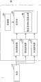
图1是具有作为本发明的一个实施方式的电池状态检测装置20的电池监视系统1的整体结构图。FIG. 1 is an overall configuration diagram of a
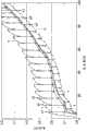
图2是表示“开路电压-充电率”的相关关系的实测数据。FIG. 2 is actual measurement data showing the correlation of "open circuit voltage-charging rate".
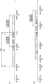
图3是表示放电侧表和充电侧表的应用期间的图。FIG. 3 is a diagram showing application periods of a discharge-side meter and a charge-side meter.
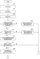
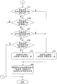
图4A是表示运算部24的动作流程的图。FIG. 4A is a diagram showing an operation flow of the
图4B是表示运算部24的动作流程的图。FIG. 4B is a diagram showing an operation flow of the
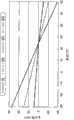
图5是表示“开路电压-周围温度”特性的图。Fig. 5 is a graph showing "open circuit voltage - ambient temperature" characteristics.
具体实施方式 Detailed ways
下面,参照附图对用于实施本发明的方式进行说明。图1是具有作为本发明的一个实施方式的电池状态检测装置20的电池监视系统1的整体结构图。电池监视系统1具备:二次电池10、和用于检测二次电池10的状态的电池状态检测装置20。作为二次电池10的具体示例,可以列举锂离子电池、镍氢电池等。电池状态检测装置20具备电压检测器21、温度检测器22、存储器23以及运算部24。电池状态检测装置20也可以具备用于检测二次电池10的充放电电流(输入输出电流)的电流检测器27。电压检测器21等电池状态检测装置20的这些构成要素例如由集成电路构成。Hereinafter, modes for implementing the present invention will be described with reference to the drawings. FIG. 1 is an overall configuration diagram of a
电压检测器21是用于检测二次电池10的输出电压的电压检测单元。电压检测器21将二次电池10的输出电压的检测数据输出到运算部24。并且,电压检测器21将二次电池10的充放电电流(输入输出电流)至少在预定的第一阈值(例如,零或者比零稍大的值)以下的状态下的二次电池10的输出电压作为二次电池10的开路电压检测出来。并且,电压检测器21也可以是,将在稳定的二次电池10的两极间开路或者有高阻抗时测得的两极间电压、或者在与二次电池10和电池状态检测装置20相连的外部设备(例如移动电话机、游戏机等便携设备)的待机状态电流(例如,1mA以下)的负载下测得的两极间电压,作为二次电池10的开路电压检测出来。The
温度检测器22是用于检测二次电池10的周围温度Ta的温度检测单元。温度检测器22将二次电池10的周围温度Ta的检测数据输出到运算部24。温度检测器22也可以检测二次电池10自身的温度来作为周围温度Ta。The
运算部24是估计单元,其根据电压检测器21的电压检测数据、温度检测器22的温度检测数据、以及预先存储在存储器23中的二次电池10固有的电池特性,来估计二次电池10的剩余容量状态(特别是充电率)。作为运算部24的具体示例,可以列举内置中央运算处理装置等的微型计算机。作为存储用于确定二次电池10的电池特性的特性参数的存储器23的具体示例,可以列举EEPROM、闪速存储器等。The
运算部24具有稳定等待时间算出部26来作为计算二次电池10的输出电压稳定所需要的稳定等待时间T的稳定等待时间算出单元。稳定等待时间T是自二次电池10的放电电流(或者也可以是充电电流)变成预定的第一阈值(例如,零或者比零稍大的值)以下起到二次电池10的每单位时间的电压变化量在预定的第二阈值(例如,零或者比零稍大的量)以下为止的待机时间。即,二次电池10的输出电压稳定的电压稳定状态相当于,二次电池10的放电电流(或者也可以是充电电流)在预定的第一阈值以下的状态持续了稳定等待时间T以上的状态。稳定等待时间算出部26例如优选为,根据二次电池10的输出电压、充放电电流和周围温度等检测值、以及能够根据这些检测值导出的容量保持率(劣化率)的算出值中的至少任一个,利用运算部24的计时器(计时单元),来算出至迁移到电压稳定状态为止的稳定等待时间T。稳定等待时间T的算出方法可以使用公知的方法,可以不特别限定。The
另外,运算部24是充电率算出单元,其将由电压检测器21检测到的二次电池10的充电后的开路电压,应用于表示二次电池10的充电后的开路电压与二次电池10的充电率之间的关系的第一电池特性,来算出二次电池10的充电率,将由电压检测器21检测到的二次电池10的放电后的开路电压,应用于表示二次电池10的放电后的开路电压与二次电池10的充电率之间的关系的第二电池特性,来算出二次电池10的充电率。用于确定第一电池特性的第一特性数据和用于确定第二电池特性的第二特性数据预先存储在存储器23中。In addition, the
所谓充电率,是指在将当时时刻的二次电池10的满充电容量作为100时以百分率来表示二次电池10的剩余容量的比例的意思。表示为了算出充电率所需要的“开路电压-充电率”的相关关系的电池特性利用修正表或修正函数来表示。修正表内的数据和修正函数的系数被作为特性数据而存储在存储器23中。运算部24根据反映了从存储器23读出的特性数据的修正表或修正函数,对应于由电压检测器21测得的开路电压,来进行充电率的算出和修正。The term "charging rate" refers to the ratio of the remaining capacity of the
针对“开路电压-充电率”这一相关关系,根据预先实测的结果(参照图2)而确定出的特性数据被存储于存储器23。在图2中,特性曲线a是重复进行每当从剩余容量0mAh的状态充电预定量(50mAh)使其预定时间(4小时)无负载时的实测数据。从特性曲线a可见,充电中两极间电压上升,在4小时无负载的a1、a2、a3···的状态下,开路电压降低。在该情况下,充电后4小时无负载状态下的“开路电压-充电率”的信息,被作为二次电池10的充电后的针对每个充电率的开路电压数据而存储于存储器23。另外,特性曲线c是将充电后4小时无负载状态下的开路电压连结而得到的曲线。With regard to the correlation relationship of “open circuit voltage-charging rate”, characteristic data determined based on the results of actual measurement in advance (see FIG. 2 ) are stored in the
另一方面,特性曲线b是重复进行每当从满充电的状态放电预定量(50mAh)使其预定时间(4小时)无负载时的实测数据。从特性曲线b可见,放电中开路电压降低,在4小时无负载的b1、b2、b3…的状态下,开路电压上升。在该情况下,放电后4小时无负载状态下的“开路电压-充电率”的信息,被作为二次电池10的放电后的针对每个充电率的开路电压数据而存储于存储器23。另外,特性曲线d是将放电后4小时无负载状态的开路电压连结而得到的曲线。特性曲线d与从满充电的状态使用以3mA进行经常放电时的特性曲线e大致重叠。On the other hand, the characteristic curve b is actual measurement data when a predetermined amount of discharge (50 mAh) is repeatedly performed from a fully charged state to make it unloaded for a predetermined time (4 hours). It can be seen from the characteristic curve b that the open circuit voltage decreases during discharge, and in the state of b1, b2, b3... without load for 4 hours, the open circuit voltage rises. In this case, the information of “open circuit voltage-charging rate” in the no-load state for 4 hours after discharge is stored in
另外,关于上述的充放电容量50mAh、无负载时间4小时,以根据系统的处理方法设为最佳值为宜。In addition, regarding the above-mentioned charging and discharging capacity of 50 mAh and no-load time of 4 hours, it is appropriate to set the optimal values according to the processing method of the system.
存储在存储器23中的放电后的针对每个充电率的开路电压数据与放电后的针对每个充电率的开路电压数据可以均为测得的电压数据,但是也可以是充电后的针对每个充电率的开路电压数据与放电后的针对每个充电率的开路电压数据的任一方用通过与另一方的差分确定的电压数据来表示。即,任一方的开路电压数据可以将其测定电压的值直接存储在存储器23中。由此,能够削减存储器23所要求的存储容量。运算部24根据任一方的开路电压数据与另一方的差分电压数据能够运算该另一方的开路数据电压。The open-circuit voltage data for each charge rate after discharge and the open-circuit voltage data for each charge rate after discharge stored in the
特性曲线a和特性曲线b的针对每个充电率的差电压相当于充电后的开路电压数据与放电后的开路电压数据之间的差分电压数据。例如,将充电后的开路电压数据作为测定电压数据进行存储,将放电后的开路电压数据作为差分电压数据进行存储。也可以反过来。如图2所示,开路电压的绝对值是以数V为单位,与此相对,差电压是以数十mV为单位。因此,通过将充电后与放电后的任一方的开路电压数据用差电压数据来进行存储,与将充电后与放电后两者的开路电压用其绝对值进行存储的情况相比,能够大幅度削减存储器23的存储容量的需要量。The difference voltage for each charging rate of the characteristic curve a and the characteristic curve b corresponds to differential voltage data between the open circuit voltage data after charging and the open circuit voltage data after discharging. For example, open circuit voltage data after charging is stored as measured voltage data, and open circuit voltage data after discharge is stored as differential voltage data. It can also be reversed. As shown in FIG. 2 , the absolute value of the open circuit voltage is in units of several volts, whereas the difference voltage is in units of several tens of mV. Therefore, by storing either open circuit voltage data after charging or after discharge as differential voltage data, compared with the case where the open circuit voltages after charging and after discharging are stored as their absolute values, the The required storage capacity of the
接下来,对运算部24算出充电率时的处理方法进行说明。运算部24,例如,根据从二次电池10的充电结束时刻起的放电容量以及二次电池10充电结束时刻起的经过时间,来选择存储充电后的针对每个充电率的开路电压数据组的“开路电压-充电率”、和放电后的针对每个充电率的开路电压数据组的“开路电压-充电率”中的某一方。然后,根据所选择的表,来算出充电率。图3是表示选择应用了充电侧表或者放电侧表的期间的图。二次电池10的充电期间相当于从充电开始时刻t1到充电结束时刻t2为止的期间。Next, a processing method when the
如图3(a)所示,运算部24,在判断为在充电结束时刻t2后、在由于无负载或者微放电而不产生预定的基准容量A1以上的放电的状况下二次电池10的输出电压稳定的情况下(例如,经过了从充电结束时刻t2到电压稳定时刻t3为止的期间(即,上述的稳定等待时间T)的情况下),由电压检测器21检测到的开路电压为“充电后的开路电压”,根据充电侧表来算出充电率。As shown in FIG. 3( a ), the
但是,充电结束时刻t2后的负载状态未必是无负载状态,也有时通过以二次电池10为电源的未图示的外部设备(例如,移动电话机、游戏机等),形成持续流过数mA程度的消耗电流的微放电的状态。因此,将在从充电结束时刻t2起经过一定程度的时间后的时刻检测出的开路电压作为“充电后的开路电压”处理被认为是不合适的。因此,可以根据充电侧表来算出充电率的期间,必须是从充电结束时刻t2起的经过时间不到预定的基准时间A2。However, the load state after the charging end time t2 is not necessarily a no-load state, and there may be cases where the
另外,基准容量A1和基准时间A2以根据二次电池10的电池的特性、从二次电池10进行供电的外部设备的消耗电流来确定为宜。In addition, the reference capacity A1 and the reference time A2 are preferably determined according to the battery characteristics of the
此外,运算部24,当在充电结束时刻t2后发生了基准容量A1以上的放电的情况下,如果未发生一定的放电量或者放电时间,则难以判别以放电侧表和充电侧表中的哪一个表为基准能够算出准确的充电率。因此,例如,运算部24,在充电结束时刻t2后,中止根据二次电池10的输出电压来算出充电率的处理,直到发生与二次电池10的电池的特性等对应的一定的放电容量(例如,大于基准容量A1的基准容量B1)或者放电时间(例如,长于基准时间A2的基准时间B2)为止,由此,能够防止充电率的算出误差变大。In addition, when the discharge of the reference capacity A1 or more has occurred after the charging end time t2, it is difficult for the
另外,如图3(a)所示,运算部24,在充电结束时刻t2后,在通过微放电而发生了一定的放电容量(例如,基准容量B1)后(或者,自充电结束时刻t2起的经过时间经过了预定的基准时间B2以上后),在二次电池10的输出电压在电压稳定开始时刻t3以后仍然稳定的情况下,由电压检测器21检测到的开路电压为“放电后的开路电压”,根据放电侧表来算出充电率、另外,运算部24,如图3(b)所示,在充电结束时刻t12后,在由于超过微放电的大的放电(t13~t14)而发生了一定的放电容量(例如,基准容量B)后(或者,自充电结束时刻t2起的经过时间经过了预定的基准时间B2以上后),在二次电池10的输出电压在电压稳定开始时刻t15后仍然稳定的情况下,由电压检测器21检测到的开路电压被作为“放电后的开路电压”,根据放电侧表来算出充电率。另外,在图3(b)中,从放电结束时刻t14到电压稳定开始时刻t15为止的期间相当于上述的稳定等待时间T。In addition, as shown in FIG. 3( a ), the
图4A、图4B是二次电池10的充电率的算出处理流程。运算部24在检测到了预定的第一阈值以下的二次电池10的充放电电流的情况下,开始遵循本流程的动作。4A and 4B are the calculation processing flow of the charging rate of the
运算部24利用电压检测器21检测二次电池10的输出电压作为开路电压(步骤S11)。另外,运算部24通过电流检测器27测定二次电池10的充放电电流(步骤S13)。然后,运算部24利用温度检测器22来测定二次电池10的周围温度(步骤S15),从步骤S11到15可以不限定于该顺序。The calculating
稳定等待时间算出部26,在二次电池10的周围温度Ta与充放电电流的至少某一方相对于经过已经算出的稳定等待时间T前发生了超出预定的基准的变动的情况下,使用伴随着该变动而变化的值如上所述重新算出稳定等待时间T,并将稳定等待时间T的寄存器值更新为再次算出的值(步骤S17~23)。The stabilization waiting
例如,在一定期间内检测到了超过基准值的温度的情况下,在该检测后的时刻再次设定需要的稳定等待时间T。由于即使二次电池10的周围温度的变动稳定,而直到二次电池10自身的温度稳定有时间延迟,因此,有时测定的开路电压或电池温度等电池状态不稳定。因此,通过根据周围温度Ta或充放电电流变动前的周围温度Ta等电池状态来估计二次电池10的剩余容量状态,其估计误差可能放大。但是,通过如步骤S17~23那样延长稳定等待时间T,能够抑制这样的估计误差的放大。这样,通过在检测到了温度变化等的情况下延长稳定等待时间T,能够测定更加准确的开路电压和周围温度等电池状态,使后述的充电率的算出时期推迟,能够提高算出的充电率的精度。For example, when a temperature exceeding a reference value is detected within a certain period of time, the required stabilization waiting time T is set again at the time after the detection. Even if the fluctuation of the ambient temperature of the
例如,在步骤S17中,在自检测到预定的第一阈值以下的二次电池10的充放电电流起在一定时间的期间内检测到了超过基准值的周围温度Ta的变动的情况下,稳定等待时间算出部26再次算出与已经算出的容量保持率K和变动后的周围温度Ta对应的稳定等待时间T,并将寄存器值更新为该再次算出的值(步骤S19)。For example, in step S17, when a change in the ambient temperature Ta exceeding the reference value is detected within a certain period of time since the detection of the charging and discharging current of the
另外,例如,在步骤S21中,流过预定的阈值以上的二次电池10的充放电电流是再次计算稳定等待时间T的条件,也成为容量保持率K的变动因素,因此,稳定等待时间算出部26再次算出与已经测定的周围温度K和变动后的容量保持率K对应的稳定等待时间T,并将寄存器值更新为该再次算出的值(步骤S23)。In addition, for example, in step S21, the charging and discharging current flowing through the
在步骤S17、S21中,运算部24在二次电池10的周围温度Ta和充放电电流均未超过预定的基准的情况下(例如,是一定的范围内的变动的情况下),仅将稳定等待时间T的寄存器值减去预定值(步骤S25),判断是否经过了稳定等待时间T,即稳定等待时间T的寄存器值是否为零(步骤S27)。如果没有经过稳定等待时间T,则返回本流程的最开始。In steps S17 and S21, when neither the ambient temperature Ta of the
如果经过了等待时间T,则运算部24根据预先存储在存储器23中的表示“开路电压-充电率”特性(图5)的特性数据,对应于在稳定等待时间T以后的电压稳定状态下测得的周围温度(或者在步骤S15中测得的周围温度),将在稳定等待时间T以后的电压稳定状态测得的开路电压(或者在步骤S11中测得的开路电压)修正成25℃条件(步骤S29)。“开路电压-充电率”特性(图5)表示以25℃为基准的各温度下的开路电压的偏移量。在图5中,示出了二次电池10的针对每个充电率的开路电压的偏移量。由此,能够以温度修正开路电压,能够抑制充电率的算出误差的增加。If the waiting time T has elapsed, the
在图4B中,运算部24判断自充电结束时刻起的放电容量是否在预定的第一基准容量B1以上(步骤S31)。运算部24在判断为在基准容量B1以上的情况下,如图3(b)所示,在充电结束时刻t1后产生大的放电,在其产生后无负载或者微放电的负载状态持续因而输出电压在定时t15稳定,选择确定了放电后的充电率与开路电压的关系的“开路电压-充电率”作为充电率算出用表(步骤S33)。In FIG. 4B , computing
运算部24,根据存储于存储器23的表示“放电侧表”的特性数据,将与在步骤S29中修正为25℃条件的开路电压对应的充电率作为二次电池10的剩余容量状态算出,将充电率的寄存器值更新为该算出值(步骤S43)。The
另一方面,运算部24在步骤S31中在判断为不在基准容量B1以上的情况下,判断自充电结束时刻起的放电容量是否不足预定的第二基准容量A1(步骤S35)。基准容量A1是比基准容量B1小的值。运算部24在判断为并非不足基准容量A1的情况下,自充电结束时刻t2起的放电量增大,难以区别由电压检测器21检测到的开路电压是放电后的开路电压还是充电后的开路电压,不实施充电率的寄存器值的更新。On the other hand, when it is determined in step S31 that the
当运算部24在步骤S35中判断为不足基准容量A1的情况下,判断自充电结束时刻起的经过时间是否在预定的第一基准时间B2以上(步骤S37)。运算部24在判断为在基准时间B2以上的情况下,将由电压检测器21检测到的开路电压作为“放电后的开路电压”,选择放电侧表作为充电率算出用表(步骤S33)。之后的步骤S43的处理与上述相同。例如,如果是图3(a)的状况,在基准时间B2的经过时刻t5到电压不稳定时刻t6为止的期间选择放电侧表,如果是图3(b)的状况,在从电压稳定时刻t15到电压不稳定时刻t16为止的期间选择放电侧表。电压不稳定时刻t6或者t16是充放电电流超过可以将开路电压视为不稳定的预定值的时刻。When the
另一方面,在步骤S35中判断为不足基准容量A1的运算部24,当在步骤S37中判断为不足基准时间B2的情况下,判断自充电结束时刻起的放电容量是否不足预定的第二基准时间A2(步骤S39)。基准时间A2是比基准时间B2短的长度。运算部24,在判断为并非不足基准时间A2的情况下,自充电结束时刻t2起的经过时间变长,难以区别由电压检测器21检测到的开路电压是放电后的开路电压还是充电后的开路电压,不实施充电率的寄存器值的更新。On the other hand, when it is determined in step S35 that it is less than the reference capacity A1, the
当运算部24在步骤S39中判断为不足基准时间A2的情况下,将由电压检测器21检测到的开路电压作为“充电后的开路电压”,选择充电侧表作为充电率算出用表(步骤S41)。例如,如果是图3(a)的状况,在从电压稳定时刻t3到基准时间A2的经过时刻t4为止的期间内选择充电侧表。When the
运算部24根据存储于存储器23的表示“充电侧表”的特性数据,来将与在步骤S29中修正为25℃条件的开路电压对应的充电率作为二次电池10的剩余容量状态算出,将充电率的寄存器值更新为该算出值(步骤S43)。
因此,根据上述的实施例,对充电后的开路电压和放电后的开路电压进行区别测定,并有选择地应用充电侧表和放电侧表作为充电率算出用表,由此始终能够算出准确的充电率而与充电后和放电后的状态无关。Therefore, according to the above-mentioned embodiment, the open-circuit voltage after charging and the open-circuit voltage after discharging are measured separately, and the table on the charging side and the table on the discharging side are selectively used as the table for calculating the charging rate, thereby always being able to calculate an accurate voltage. The charging rate has nothing to do with the state after charging and after discharging.
以上,对本发明的优选的实施例进行了说明,但是本发明并不限于上述实施例,在不脱离本发明的范围的情况下能够对上述实施例加以各种变形、改良和置换。The preferred embodiments of the present invention have been described above, but the present invention is not limited to the above-described embodiments, and various modifications, improvements, and substitutions can be added to the above-described embodiments without departing from the scope of the present invention.
例如,在图2中,也可以将充电后的无负载状态下的特性曲线c和/或放电后的无负载状态下的特性曲线d通过曲线拟合(curve fit)处理用多项式的近似模型函数来表示,将该多项式的各系数预先存储在存储器23中。由此,与直接存储针对每个充电率的开路电压数据的情况相比,能够削减存储器23的容量。For example, in FIG. 2, the characteristic curve c in the no-load state after charging and/or the characteristic curve d in the no-load state after discharge can also be processed by curve fitting (curve fit) using a polynomial approximate model function to represent that each coefficient of the polynomial is stored in the
本国际申请主张基于2010年2月19日提出申请的日本专利申请2010-035128号的优先权,并将2010-035128号的全部内容援引到本国际申请中。This international application claims priority based on Japanese Patent Application No. 2010-035128 for which it applied on February 19, 2010, and uses all the content of 2010-035128 for this international application.
符号说明Symbol Description
1 电池监视系统1 Battery Monitoring System
10 二次电池10 secondary batteries
20 电池状态检测装置20 battery status detection device
21 电压检测器21 voltage detector
22 温度检测器22 temperature detector
23 存储器23 memory
24 运算部24 Computing department
26 稳定等待时间算出部26 Stability waiting time calculation part
27 电流检测器27 Current detector
Claims (10)
Applications Claiming Priority (3)
| Application Number | Priority Date | Filing Date | Title |
|---|---|---|---|
| JP2010-035128 | 2010-02-19 | ||
| JP2010035128A JP5732725B2 (en) | 2010-02-19 | 2010-02-19 | Battery state detection device |
| PCT/JP2011/050961 WO2011102179A1 (en) | 2010-02-19 | 2011-01-20 | Battery state detection device |
Publications (2)
| Publication Number | Publication Date |
|---|---|
| CN102762995A true CN102762995A (en) | 2012-10-31 |
| CN102762995B CN102762995B (en) | 2014-11-19 |
Family
ID=44482780
Family Applications (1)
| Application Number | Title | Priority Date | Filing Date |
|---|---|---|---|
| CN201180009971.7A Active CN102762995B (en) | 2010-02-19 | 2011-01-20 | Battery state detection device and battery state detection method |
Country Status (4)
| Country | Link |
|---|---|
| US (1) | US20120290236A1 (en) |
| JP (1) | JP5732725B2 (en) |
| CN (1) | CN102762995B (en) |
| WO (1) | WO2011102179A1 (en) |
Cited By (4)
| Publication number | Priority date | Publication date | Assignee | Title |
|---|---|---|---|---|
| CN107076802A (en) * | 2014-12-05 | 2017-08-18 | 古河电气工业株式会社 | Secondary cell condition checkout gear and secondary cell condition detection method |
| CN111308357A (en) * | 2020-04-01 | 2020-06-19 | 一汽解放汽车有限公司 | Battery capacity estimation method, battery management system, vehicle, and storage medium |
| CN112051433A (en) * | 2019-06-06 | 2020-12-08 | 松下电器(美国)知识产权公司 | Open-circuit voltage measurement method, open-circuit voltage measurement device, and recording medium |
| CN117317418A (en) * | 2023-11-29 | 2023-12-29 | 珠海智锐科技有限公司 | A battery control method for BMS management system |
Families Citing this family (22)
| Publication number | Priority date | Publication date | Assignee | Title |
|---|---|---|---|---|
| JP5870590B2 (en) * | 2011-09-29 | 2016-03-01 | ミツミ電機株式会社 | Battery state measuring method and battery state measuring apparatus |
| JP2013083612A (en) * | 2011-10-12 | 2013-05-09 | Mitsumi Electric Co Ltd | Battery state measurement method and battery state measurement apparatus |
| WO2013094126A1 (en) * | 2011-12-22 | 2013-06-27 | パナソニック株式会社 | Electronic device and electronic device charging system |
| JP5768772B2 (en) * | 2012-06-29 | 2015-08-26 | 株式会社豊田自動織機 | Power storage system and charging rate estimation method |
| TWI460453B (en) * | 2012-09-28 | 2014-11-11 | Metal Ind Res & Dev Ct | Battery residual energy estimation system synthesized by two mutually perpendicular components and its estimation method |
| CN102928785A (en) * | 2012-10-16 | 2013-02-13 | 西安思坦仪器股份有限公司 | Battery power measuring instrument and measuring method |
| JP2014102248A (en) * | 2012-10-24 | 2014-06-05 | Gs Yuasa Corp | Power storage state detection apparatus |
| US9552031B2 (en) | 2013-12-20 | 2017-01-24 | Facebook, Inc. | Power shelf for computer servers |
| DE102014200673A1 (en) * | 2014-01-16 | 2015-07-16 | Robert Bosch Gmbh | Method for monitoring a battery |
| FR3025889B1 (en) * | 2014-09-12 | 2016-11-18 | Commissariat Energie Atomique | MANAGING THE RECHARGE OF THE BATTERY OF AN ELECTRIC VEHICLE |
| US10386421B2 (en) * | 2015-09-14 | 2019-08-20 | Facebook, Inc. | Energy based battery backup unit testing |
| US10063092B2 (en) | 2015-10-02 | 2018-08-28 | Facebook, Inc. | Data center power network with multiple redundancies |
| US9986658B2 (en) | 2015-12-03 | 2018-05-29 | Facebook, Inc | Power connection clip for a shelf in a server rack |
| JP6830318B2 (en) | 2016-01-15 | 2021-02-17 | 株式会社Gsユアサ | Power storage element management device, power storage element module, vehicle and power storage element management method |
| JP6930572B2 (en) * | 2016-01-15 | 2021-09-01 | 株式会社Gsユアサ | Power storage element management device, power storage element module, vehicle and power storage element management method |
| US10123450B2 (en) | 2016-05-12 | 2018-11-06 | Facebook, Inc. | High voltage direct current power generator for computer server data centers |
| KR102458526B1 (en) | 2018-02-07 | 2022-10-25 | 주식회사 엘지에너지솔루션 | Apparatus and method for estimating soc base on operating state of battery |
| JP6958427B2 (en) * | 2018-02-27 | 2021-11-02 | トヨタ自動車株式会社 | Rechargeable battery system |
| JP7111969B2 (en) | 2018-10-30 | 2022-08-03 | ミツミ電機株式会社 | Electronic device and its control method |
| JP7044044B2 (en) * | 2018-12-07 | 2022-03-30 | トヨタ自動車株式会社 | Deterioration degree estimation device for secondary batteries and deterioration degree estimation method for secondary batteries |
| JP7244746B2 (en) | 2019-02-22 | 2023-03-23 | ミツミ電機株式会社 | ELECTRONIC DEVICE AND ITS STATE DETERMINATION METHOD |
| KR102780292B1 (en) | 2019-12-11 | 2025-03-11 | 주식회사 엘지에너지솔루션 | Battery management system, battery management method, battery pack, and electric vehicle |
Citations (4)
| Publication number | Priority date | Publication date | Assignee | Title |
|---|---|---|---|---|
| JPH11289685A (en) * | 1998-04-01 | 1999-10-19 | Toshiba Battery Co Ltd | Device for detecting charged state of secondary battery |
| CN1182407C (en) * | 2003-01-16 | 2004-12-29 | 华南理工大学 | Method and device for measuring lithium-ion battery power |
| JP2007327971A (en) * | 2002-11-27 | 2007-12-20 | Fuji Electric Device Technology Co Ltd | Battery level measuring device |
| WO2010003361A1 (en) * | 2008-07-08 | 2010-01-14 | 奇瑞汽车股份有限公司 | Method and device for forecasting battery charge |
Family Cites Families (3)
| Publication number | Priority date | Publication date | Assignee | Title |
|---|---|---|---|---|
| US4344142A (en) * | 1974-05-23 | 1982-08-10 | Federal-Mogul Corporation | Direct digital control of rubber molding presses |
| JP2878953B2 (en) * | 1993-12-27 | 1999-04-05 | 本田技研工業株式会社 | Method for detecting remaining capacity of battery for electric vehicle |
| JP4631880B2 (en) * | 2007-07-30 | 2011-02-16 | ミツミ電機株式会社 | Battery status detection method |
-
2010
- 2010-02-19 JP JP2010035128A patent/JP5732725B2/en active Active
-
2011
- 2011-01-20 CN CN201180009971.7A patent/CN102762995B/en active Active
- 2011-01-20 WO PCT/JP2011/050961 patent/WO2011102179A1/en not_active Ceased
- 2011-01-20 US US13/519,365 patent/US20120290236A1/en not_active Abandoned
Patent Citations (4)
| Publication number | Priority date | Publication date | Assignee | Title |
|---|---|---|---|---|
| JPH11289685A (en) * | 1998-04-01 | 1999-10-19 | Toshiba Battery Co Ltd | Device for detecting charged state of secondary battery |
| JP2007327971A (en) * | 2002-11-27 | 2007-12-20 | Fuji Electric Device Technology Co Ltd | Battery level measuring device |
| CN1182407C (en) * | 2003-01-16 | 2004-12-29 | 华南理工大学 | Method and device for measuring lithium-ion battery power |
| WO2010003361A1 (en) * | 2008-07-08 | 2010-01-14 | 奇瑞汽车股份有限公司 | Method and device for forecasting battery charge |
Cited By (8)
| Publication number | Priority date | Publication date | Assignee | Title |
|---|---|---|---|---|
| CN107076802A (en) * | 2014-12-05 | 2017-08-18 | 古河电气工业株式会社 | Secondary cell condition checkout gear and secondary cell condition detection method |
| US10656210B2 (en) | 2014-12-05 | 2020-05-19 | Furukawa Electric Co., Ltd. | Secondary battery state detection device and secondary battery state detection method |
| CN107076802B (en) * | 2014-12-05 | 2020-12-29 | 古河电气工业株式会社 | Secondary battery state detection device and secondary battery state detection method |
| CN112051433A (en) * | 2019-06-06 | 2020-12-08 | 松下电器(美国)知识产权公司 | Open-circuit voltage measurement method, open-circuit voltage measurement device, and recording medium |
| CN112051433B (en) * | 2019-06-06 | 2024-06-07 | 松下电器(美国)知识产权公司 | Open circuit voltage measurement method, open circuit voltage measurement device, and recording medium |
| CN111308357A (en) * | 2020-04-01 | 2020-06-19 | 一汽解放汽车有限公司 | Battery capacity estimation method, battery management system, vehicle, and storage medium |
| CN117317418A (en) * | 2023-11-29 | 2023-12-29 | 珠海智锐科技有限公司 | A battery control method for BMS management system |
| CN117317418B (en) * | 2023-11-29 | 2024-02-13 | 珠海智锐科技有限公司 | Battery control method of BMS management system |
Also Published As
| Publication number | Publication date |
|---|---|
| JP2011169817A (en) | 2011-09-01 |
| US20120290236A1 (en) | 2012-11-15 |
| WO2011102179A1 (en) | 2011-08-25 |
| CN102762995B (en) | 2014-11-19 |
| JP5732725B2 (en) | 2015-06-10 |
Similar Documents
| Publication | Publication Date | Title |
|---|---|---|
| CN102762995B (en) | Battery state detection device and battery state detection method | |
| US9651628B2 (en) | Method and apparatus for determining a capacity of a battery | |
| CN102725647A (en) | Battery state detection device and battery state detection method | |
| US9869724B2 (en) | Power management system | |
| US8660809B2 (en) | Method for accurate battery run time estimation utilizing adaptive offset values | |
| US9651624B2 (en) | Systems and methods for state of charge estimation | |
| CN101443949B (en) | Method and apparatus for controlling battery | |
| JP5535968B2 (en) | CHARGE RATE ESTIMATION DEVICE, CHARGE RATE ESTIMATION METHOD, AND PROGRAM | |
| EP2761316A2 (en) | System and method for battery monitoring | |
| JP2013083612A (en) | Battery state measurement method and battery state measurement apparatus | |
| CN102144171A (en) | Battery state detection device and battery pack incorporating same, and battery state detection method | |
| KR20080099121A (en) | How to detect battery packs, electronic devices, and battery level | |
| JP5870590B2 (en) | Battery state measuring method and battery state measuring apparatus | |
| CN108291944A (en) | Battery status estimating device, battery control device, battery system, battery status estimate method | |
| JP4525347B2 (en) | Battery pack and remaining battery capacity calculation method | |
| JP4764971B2 (en) | Battery level measuring device | |
| US9891287B2 (en) | Temperature-compensated state of charge estimation for rechargeable batteries | |
| JP4016881B2 (en) | Battery level measuring device | |
| KR20180082020A (en) | device for detecting the state of charge of a battery | |
| JP4329543B2 (en) | Battery level measuring device | |
| JP2015094710A (en) | Battery health estimation device and health estimation method | |
| JP2015025686A (en) | Secondary battery pack management method, power management system, and electronic device | |
| JP2002181906A (en) | Battery remaining capacity calculation method and device to calculate | |
| JP2023528522A (en) | Apparatus and method for detecting lithium deposition | |
| CN119716604A (en) | Method and device for determining state of charge, storage medium, and electronic device |
Legal Events
| Date | Code | Title | Description |
|---|---|---|---|
| C06 | Publication | ||
| PB01 | Publication | ||
| C10 | Entry into substantive examination | ||
| SE01 | Entry into force of request for substantive examination | ||
| C14 | Grant of patent or utility model | ||
| GR01 | Patent grant |