CN102765254A - Phase different electronic calibration system of multiple-spray-head printing spray points - Google Patents
Phase different electronic calibration system of multiple-spray-head printing spray points Download PDFInfo
- Publication number
- CN102765254A CN102765254A CN2012102843987A CN201210284398A CN102765254A CN 102765254 A CN102765254 A CN 102765254A CN 2012102843987 A CN2012102843987 A CN 2012102843987A CN 201210284398 A CN201210284398 A CN 201210284398A CN 102765254 A CN102765254 A CN 102765254A
- Authority
- CN
- China
- Prior art keywords
- nozzle
- phase
- signal
- ignition
- nozzles
- Prior art date
- Legal status (The legal status is an assumption and is not a legal conclusion. Google has not performed a legal analysis and makes no representation as to the accuracy of the status listed.)
- Granted
Links
Images


Landscapes
- Ink Jet (AREA)
Abstract
本发明涉及多喷头喷墨打印机领域,一种多喷头打印喷点的相位差电子校准系统,包括:主板、相位逻辑处理单元、第一和第二异步FIFO、第一和第二驱动电路,及第一和第二喷头。采用电子校准技术,降低了机器校准难度,以及简化了机械校准机构。用喷头小车方向信号来判别相位的正负,降低了相位逻辑处理单元的复杂度,同时提高了可靠性。相位的传送采用脉冲宽度来表示,提高了主板控制两喷头相位差的灵活性,可靠性。相位逻辑处理单元同主板的分离,巧妙了保留原有的主板设计结果,不仅降低了开发成本,也加快了开发进度。本发明减少了主板与喷头驱动电路的信号数量,降低了成本,提高了主板信号发送的可靠性。
The invention relates to the field of multi-jet inkjet printers, and relates to a phase difference electronic calibration system for printing dots with multiple nozzles, comprising: a main board, a phase logic processing unit, first and second asynchronous FIFOs, first and second drive circuits, and First and second nozzles. The use of electronic calibration technology reduces the difficulty of machine calibration and simplifies the mechanical calibration mechanism. Using the direction signal of the nozzle trolley to judge the positive and negative of the phase reduces the complexity of the phase logic processing unit and improves the reliability at the same time. The transmission of the phase is represented by the pulse width, which improves the flexibility and reliability of the main board to control the phase difference between the two nozzles. The separation of the phase logic processing unit from the main board cleverly retains the original design results of the main board, which not only reduces the development cost, but also speeds up the development progress. The invention reduces the number of signals of the main board and the nozzle driving circuit, reduces the cost, and improves the reliability of signal transmission of the main board.
Description
技术领域 technical field
本发明涉及多喷头喷墨打印机领域,尤其涉一种多喷头打印喷点的相位差电子较准系统。The invention relates to the field of multi-nozzle inkjet printers, in particular to a phase difference electronic calibration system for multi-nozzle printing dots.
背景技术 Background technique
目前多喷头打印机已经广泛应用,但是由于每个喷头独立安装,期间会产生角度、距离的偏差。例如图1-2所示,打印机的喷头小车3上安装有2个喷头:基准喷头1和校准喷头2。如图1所示,基准喷头1和校准喷头2之间的前后方向上距离误差D1和角度差,这个误差可以通过手动调节很容易解决;但是基准喷头1和校准喷头2之间的左右方向上距离误差D2,很难手动精确校准。若点火周期误差为d1,当两喷头左右之间的距离误差D2刚好是点火周期误差的整数倍,即D2=nd1(n为整数),可以通过延时点火解决;但如图2所示,当两喷头左右之间的距离误差D2不是点火周期误差的整数倍,即D2=nd1+d2(n为点火周期个数,d2<d1),则延迟点火只能消除点火周期误差的整数倍nd1(n为整数),剩余误差d2则很难精确校准。以上所述点火周期误差d1,是指同一个喷孔,相邻一个点火周期喷出的墨点4,在喷头小车3移动方向上的距离。点火周期误差可以通过延时一个周期或提前一个周期点火来消除。At present, multi-nozzle printers have been widely used, but because each nozzle is installed independently, there will be deviations in angle and distance during the process. For example, as shown in Figure 1-2, there are two print heads installed on the
因此在多喷头打印机中,除了基准喷头只要校准喷头的安装角度,其它的喷头要校准安装角度,前后距离,左右距离。这样导致机械结构复杂,校准难度大,而大多打印机为了简化机械结构,不进行左右方向距离误差的精确校对,打印高精度的图象效果就很差。Therefore, in a multi-nozzle printer, except for the reference nozzle, it is only necessary to calibrate the installation angle of the nozzle, and the installation angle, front-back distance, and left-right distance of other nozzles must be calibrated. This leads to complex mechanical structure and great difficulty in calibration, and most printers do not perform accurate calibration of distance errors in the left and right directions in order to simplify the mechanical structure, so the effect of printing high-precision images is very poor.
提高多喷头喷墨打印机打印精度的关键因素是提高多喷头的校准精度,现有物理校准喷头技术是通过机械装置调整每个喷头的角度、距离,保证每个喷头在同一平面上的前后及左右两个方向上达到相等距离和平行。此方式校准喷头精度需要专业技术人员操作,并且操作复杂,花费很长时间。但是在打印机实际生产作业过程中,如果用户打印机需要更换喷头而浪费大量时间在等待专业技术维修人员上,将影响打印机客户的生产效益。The key factor to improve the printing accuracy of multi-nozzle inkjet printers is to improve the calibration accuracy of multi-nozzles. The existing physical calibration nozzle technology is to adjust the angle and distance of each nozzle through mechanical devices to ensure that each nozzle is on the same plane. equal distance and parallel in both directions. Calibrating the accuracy of the nozzle in this way requires professional and technical personnel to operate, and the operation is complicated and takes a long time. However, in the actual production process of the printer, if the user printer needs to replace the nozzle and waste a lot of time waiting for professional technical maintenance personnel, it will affect the production efficiency of the printer customer.
现有的多喷头打印机,各个喷头是同时点火的,也就是说各个喷头之间的点火相位差为0,这使得各个喷头之间左右距离的装配精度要求很高,对于这种高精度的装配要求,一般是通过左右方向上的机械微调来解决。少数有实力的打印机厂家通过出售喷头组来解决,各喷头组在厂内通过高精度装配仪器校准来达到这种装配要求,但是当客户在使用当中,当喷头组中的一个喷头坏了,他只能换掉整个喷头组,这样就很浪费,使得客户使用成本高,不利于推广使用。In existing multi-nozzle printers, each nozzle is ignited at the same time, that is to say, the ignition phase difference between each nozzle is 0, which makes the assembly accuracy of the left and right distance between each nozzle very high. For this high-precision assembly The requirements are generally solved by mechanical fine-tuning in the left and right directions. A small number of powerful printer manufacturers solve the problem by selling nozzle groups. Each nozzle group is calibrated by high-precision assembly instruments in the factory to meet this assembly requirement. Only the whole nozzle group can be replaced, which is very wasteful and makes the customer's use cost high, which is not conducive to popularization and use.
发明内容 Contents of the invention
为了解决以上问题,本发明提供了一种结构简单,校准方便、精确的多喷头打印喷点的相位差电子较准系统。旨在降低喷头机械校准难度以及机械校准结构的复杂度。In order to solve the above problems, the present invention provides a simple structure, convenient calibration, and accurate phase difference electronic calibration system for printing dots with multiple nozzles. The aim is to reduce the difficulty of mechanical calibration of the nozzle and the complexity of the mechanical calibration structure.
本发明采用的技术方案是:一种多喷头打印喷点的相位差电子校准系统,包括:主板、相位逻辑处理单元、第一和第二异步FIFO、第一和第二驱动电路,及第一和第二喷头,The technical solution adopted in the present invention is: a phase difference electronic calibration system for printing nozzles with multiple nozzles, including: a main board, a phase logic processing unit, a first and a second asynchronous FIFO, a first and a second drive circuit, and a first and the second nozzle,
其中,in,
所述主板把图像数据处理成对应喷头的数据格式,并转换成串行数据,生成写异步FIFO的写使能和写时钟向所述第一和第二异步FIFO发出,并向所述的相位逻辑处理单元提供第一和第二喷头的点火相位信号,以及喷头小车方向信号,所述点火相位信号是一个脉冲信号,此信号脉冲宽度是两喷头的驱动波形的相位差,所述喷头小车方向信号是两喷头相位差的正负标志;The main board processes the image data into the data format of the corresponding nozzle, and converts it into serial data, generates a write enable and a write clock for writing to the asynchronous FIFO, sends them to the first and second asynchronous FIFOs, and sends them to the phase The logic processing unit provides the ignition phase signals of the first and second nozzles, and the direction signal of the nozzle carriage. The ignition phase signal is a pulse signal. The pulse width of this signal is the phase difference between the driving waveforms of the two nozzles. The signal is the positive and negative sign of the phase difference between the two nozzles;
所述相位逻辑处理单元通过接收主板发过来的点火相位信号和喷头小车方向信号,经过逻辑处理,根据点火相位与小车方向产生分别与所述第一和第二异步FIFO相应的读时钟与读使能,同时生成第一和第二喷头的写时钟,当相应喷头一次点火的数据读完成后,产生相应喷头的点火驱动触发信号给相应的驱动电路,相应喷头产生的点火驱动触发信号的相位差就是两喷头最终喷出墨点的相位差;The phase logic processing unit receives the ignition phase signal and the nozzle car direction signal sent by the main board, and after logic processing, generates the read clock and read command respectively corresponding to the first and second asynchronous FIFOs according to the ignition phase and the direction of the car. It can generate the write clocks of the first and second nozzles at the same time. When the data reading of one ignition of the corresponding nozzle is completed, the ignition drive trigger signal of the corresponding nozzle is generated to the corresponding drive circuit. The phase difference of the ignition drive trigger signal generated by the corresponding nozzle It is the phase difference of the ink dots finally ejected by the two nozzles;
所述第一和第二异步FIFO是两个相同数据宽度的异步FIFO,所述第一异步FIFO缓存第一喷头的图像数据,所述第二异步FIFO缓存第二喷头的图像数据,写使能和写时钟由所述主板提供,读时钟与读使能由所述相位逻辑处理单元提供;The first and second asynchronous FIFOs are two asynchronous FIFOs with the same data width, the first asynchronous FIFO buffers the image data of the first nozzle, the second asynchronous FIFO buffers the image data of the second nozzle, write enable and the write clock are provided by the motherboard, and the read clock and read enable are provided by the phase logic processing unit;
所述第一和第二驱动电路各自接收来自相位逻辑处理单元的点火驱动触发信号,根据各自的触发信号给相应喷头发出驱动波形;Each of the first and second drive circuits receives an ignition drive trigger signal from the phase logic processing unit, and sends a drive waveform to the corresponding nozzle according to the respective trigger signal;
所述第一和第二喷头,接收各自的图像数据和驱动波形后喷出相应墨点;The first and second nozzles eject corresponding ink dots after receiving respective image data and driving waveforms;
所述逻辑处理单元生成的第一异步FIFO的读使能和读时钟,分别与所述逻辑处理单元生成的第二异步FIFO的读使能和读时钟之间相位差的大小,由所述主板的点火相位信号提供,而相位差的正负由所述主板的喷头小车方向信号提供。The read enable and read clock of the first asynchronous FIFO generated by the logic processing unit, and the phase difference between the read enable and the read clock of the second asynchronous FIFO generated by the logic processing unit respectively, are determined by the main board The ignition phase signal is provided, and the positive and negative phase difference is provided by the nozzle carriage direction signal of the main board.
进一步的,所述相位逻辑处理单元中的逻辑处理为:相位逻辑处理单元包括上升沿提取器、下降沿提取器、信号选择器、第一FIFO读时序生成器、第一喷头写脉冲生成器、第二FIFO读时序生成器、第二喷头写脉冲生成器,上升沿提取器提取主板点火相位信号的上升沿,下降沿提取器提取主板点火相位信号下降沿,当主板10喷头小车方向信号为高电平,信号选择器把上升沿提取器131提取的上升沿发给第一FIFO读时序生成器和第一喷头写脉冲生成器,把下降沿提取器提取的下降沿发给第二读时序生成器和第二喷头写脉冲生成器;当主板10喷头小车方向信号为低电平,信号选择器把下降沿提取器提取的下降沿发给第一FIFO读时序生成器和第一喷头写脉冲生成器,把上升沿提取器提取的上升沿发给第二FIFO读时序生成器和第二喷头写脉冲生成器。第一FIFO读时序生成器和第二FIFO读时序生成器根据各自接收到边沿触发信号,生成有一定相位差的两组FIFO读时序,一组是读使能1和读时钟1,一组是读使能2和读时钟2;第一喷头写脉冲生成器和第二喷头写脉冲生成器根据各自接收到边沿触发信号,生成有一定相位差的两组喷头写时序和点火信号,一组是第一喷头的写时钟1和点火1信号,一组是第二喷头的写时钟2和点火2信号;Further, the logic processing in the phase logic processing unit is as follows: the phase logic processing unit includes a rising edge extractor, a falling edge extractor, a signal selector, a first FIFO read timing generator, a first nozzle write pulse generator, The second FIFO read timing generator, the second nozzle write pulse generator, the rising edge extractor extracts the rising edge of the ignition phase signal of the main board, and the falling edge extractor extracts the falling edge of the ignition phase signal of the main board, when the
其中,第一FIFO读时序生成器根据信号选择器发过来的触发信号,向第一异步FIFO11发送一定数量的读时钟1,同时生成第一异步FIFO11读使能1信号;第一喷头写脉冲生成器,根据信号选择器发过来的触发信号,向第一喷头发送一定数量的写时钟1,待发完后,给第一驱动电路发一个点火触发1信号;Among them, the first FIFO read timing generator sends a certain number of
其中,第二FIFO读时序生成器根据信号选择器发过来的触发信号,向第二异步FIFO12发送一定数量的读时钟2,同时生成第二异步FIFO12读使能2信号;第二喷头写脉冲生成器,根据信号选择器发过来的触发信号,向第二喷头发送一定数量的写时钟2,待发完后,给第二驱动电路发一个点火触发2信号。Wherein, the second FIFO read timing generator sends a certain number of
进一步的,所述第一和第二喷头的每个喷头内所有喷孔只能同一时间喷。Further, all nozzle holes in each nozzle of the first and second nozzles can only spray at the same time.
进一步的,当喷头小车远离打印机的原点打印时,所述相位差为正,当喷头小车返回打印机原点时,所述相位差为负。Further, when the nozzle carriage is far away from the origin of the printer for printing, the phase difference is positive, and when the nozzle carriage returns to the origin of the printer, the phase difference is negative.
进一步的,相位的传送采用脉冲宽度来表示。Further, the transmission of the phase is represented by a pulse width.
本发明还描述了包括2个以上的喷头的多喷头打印喷点相位差电子校准系统,其中一个喷头作为第一喷头,其它喷头相对于第一喷头分别作为第二喷头进行校准。The present invention also describes an electronic calibration system for multi-jet print dot phase difference comprising more than two jet heads, wherein one jet head is used as the first jet head, and the other jet heads are respectively used as the second jet heads for calibration relative to the first jet head.
与现有技术采用相比,本发明具有以下优点。Compared with the prior art, the present invention has the following advantages.
1、采用电子校准技术,降低了机器校准难度,以及简化了机械校准机构。1. Adopt electronic calibration technology, which reduces the difficulty of machine calibration and simplifies the mechanical calibration mechanism.
2、用喷头小车方向信号来判别相位的正负,降低了相位逻辑处理单元的复杂度,同时提高了可靠性。2. Use the direction signal of the nozzle trolley to judge whether the phase is positive or negative, which reduces the complexity of the phase logic processing unit and improves reliability at the same time.
3、相位的传送采用脉冲宽度来表示,提高了主板控制两喷头相位差的灵活性,可靠性。3. The transmission of the phase is represented by the pulse width, which improves the flexibility and reliability of the main board to control the phase difference between the two nozzles.
4、相位逻辑处理单元同主板的分离,巧妙了保留原有的主板设计结果,不仅降低了开发成本,也加快了开发进度。4. The phase logic processing unit is separated from the main board, cleverly retaining the original design results of the main board, which not only reduces the development cost, but also speeds up the development progress.
5、本发明减少了主板与喷头驱动电路的信号数量,降低了成本,提高了主板信号发送的可靠性。5. The present invention reduces the number of signals of the main board and the nozzle driving circuit, reduces the cost, and improves the reliability of signal transmission of the main board.
附图说明 Description of drawings
图1为打印机的2个喷头之间距离误差和角度差示意图;Figure 1 is a schematic diagram of the distance error and angle difference between the two nozzles of the printer;
图2为打印机的2个喷头之间纵向距离误差与时间周期示意图;Figure 2 is a schematic diagram of the longitudinal distance error and the time period between the two nozzles of the printer;
图3为本发明的模块结构示意图;Fig. 3 is a schematic diagram of the module structure of the present invention;
图4为本发明的相位逻辑处理单元的结构示意图;Fig. 4 is a schematic structural diagram of a phase logic processing unit of the present invention;
图5为本发明的正相位波形转换逻辑图;Fig. 5 is positive phase waveform conversion logic diagram of the present invention;
图6为本发明的负相位波形转换逻辑图。FIG. 6 is a logic diagram of negative phase waveform conversion in the present invention.
具体实施方式 Detailed ways
为了使本发明的目的、技术方案及优点更加清楚明白,以下结合附图及实施例,对本发明进行进一步详细说明。应当理解,此处所描述的具体实施例仅仅用以解释本发明,并不用于限定本发明。In order to make the object, technical solution and advantages of the present invention clearer, the present invention will be further described in detail below in conjunction with the accompanying drawings and embodiments. It should be understood that the specific embodiments described here are only used to explain the present invention, not to limit the present invention.
相反,本发明涵盖任何由权利要求定义的在本发明的精髓和范围上做的替代、修改、等效方法以及方案。进一步,为了使公众对本发明有更好的了解,在下文对本发明的细节描述中,详尽描述了一些特定的细节部分。对本领域技术人员来说没有这些细节部分的描述也可以完全理解本发明。On the contrary, the invention covers any alternatives, modifications, equivalent methods and schemes within the spirit and scope of the invention as defined by the claims. Further, in order to make the public have a better understanding of the present invention, some specific details are described in detail in the detailed description of the present invention below. The present invention can be fully understood by those skilled in the art without the description of these detailed parts.
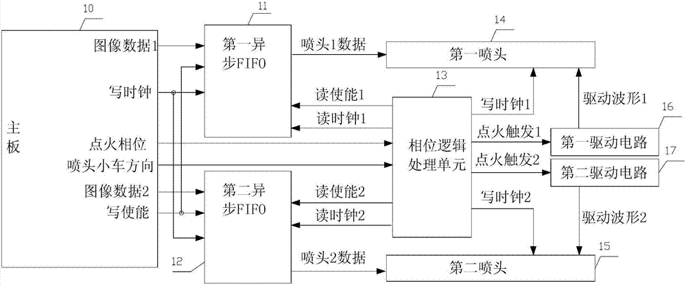
结合附图3,应用于多喷头打印喷点相位差电子校准系统包括主板10、第一异步FIFO11、第二异步FIFO12、相位逻辑处理单元13、第一喷头14、第二喷头15、第一驱动电路16和第二驱动电路17,其中:In conjunction with accompanying drawing 3, the electronic calibration system applied to multi-nozzle printing nozzle phase difference includes a
主板10把图像数据处理成对应喷头的数据格式,并转换成串行数据,生成写异步FIFO的写使能和写时钟向所述第一异步FIFO和所述第二异步FIFO发出,并向所述的相位逻辑处理单元提供两喷头的点火相位信号和喷头小车方向信号。主板10发出的点火相位信号是一个脉冲信号,此信脉冲宽度就是两喷头的相位差,主板10发出的喷头小车方向信号是两喷头相位差的正负标志。The
第一异步FIFO11和第二异步FIFO12,是两个相同数据宽度、相同写时序、相同读时序的异步FIFO,第一异步FIFO11存储从主板10发过来的第一喷头14的图像数据,第二异步FIFO12存储从主板10发过来的第二喷头15的图像数据.The first asynchronous FIFO11 and the second asynchronous FIFO12 are two asynchronous FIFOs with the same data width, the same write timing and the same read timing. The first asynchronous FIFO11 stores the image data of the
相位逻辑处理单元13,通过接收主板10发过来的点火相位信号和喷头小车方向信号,经过逻辑处理,根据点火相位与小车方向产生第一异步FIFO11与第二异步FIFO12相应的读时钟和读使能,同时生成第一喷头14与第二喷头15的写时钟,当相应喷头一次点火的数据读完后,产生一个相应喷头的点火驱动触发信号给相应的驱动电路。The phase
其中相位逻辑处理单元13生成的读使能1与读时钟1是第一异步FIFO11的读逻辑。相位逻辑处理单元13生成的读使能2与读时钟2是第二异步FIFO12的读逻辑。The read enable 1 and read
其中相位逻辑处理单元13生成的写时钟1把第一异步FIFO11读出的喷头1数据写入第一喷头14,同理相位逻辑处理单元13生成的写时钟2把第二异步FIFO12读出的喷头2数据写入第二喷头15。The
其中相位逻辑处理单元13生成的点火触发1,是在读完第一喷头14的喷头1数据(图像数据)后,生成的一个给第一驱动电路16的触发信号,同理点火触发2是相位逻辑处理单元13发给第二驱动电路17的触发信号。The
结合附图4,相位逻辑处理单元13可以包括上升沿提取器131、下降沿提取器132、信号选择器133、第一FIFO读时序生成器134、第一喷头写脉冲生成器135、第二FIFO读时序生成器132、第二喷头写脉冲生成器136。上升沿提取器131提取主板10点火相位信号的上升沿,下降沿提取器132提取主板10点火相位信号下降沿,当主板10喷头小车方向信号为高电平,信号选择器133把上升沿提取器131提取的上升沿发给第一FIFO读时序生成器134和第一喷头写脉冲生成器135,把下降沿提取器132提取的下降沿发给第二FIFO读时序生成器132和第二喷头写脉冲生成器136。当主板10喷头小车方向信号为低电平,信号选择器133把下降沿提取器132提取的下降沿发给第一FIFO读时序生成器134和第一喷头写脉冲生成器135,把上升沿提取器131提取的上升沿发给第二FIFO读时序生成器132和第二喷头写脉冲生成器136。第一FIFO读时序生成器134和第二FIFO读时序生成器132根据各自接收到边沿触发信号,生成有一定相位差的两组FIFO读时序,一组是读使能1和读时钟1,一组是读使能2和读时钟2。同理第一喷头写脉冲生成器135和第二喷头写脉冲生成器136根据各自接收到边沿触发信号,生成有一定相位差的两组喷头写时序和点火信号。一组是第一喷头的写时钟1和点火1信号,一组是第二喷头的写时钟2和点火2信号。4, the phase
其中,第一FIFO读时序生成器134根据信号选择器发过来的触发信号,向第一异步FIFO11发送一定数量的读时钟1,同时生成第一异步FIFO11读使能1信号;第一喷头写脉冲生成器135,根据信号选择器发过来的触发信号,向第一喷头14发送一定数量的写时钟1,待发完后,给第一驱动电路16发一个点火触发1信号。Wherein, the first FIFO read
其中,第二FIFO读时序生成器136根据信号选择器发过来的触发信号,向第二异步FIFO12发送一定数量的读时钟2,同时生成第二异步FIFO12读使能2信号;第二喷头写脉冲生成器137,根据信号选择器发过来的触发信号,向第二喷头15发送一定数量的写时钟2,待发完后,给第二驱动电路17发一个点火触发2信号。Wherein, the second FIFO read
第一喷头14,根据相位逻辑处理单元13发出的写时钟1,得到第一异步FIFO11读出的喷头1数据,然后由第一驱动电路16发出的驱动波形1驱动,喷出墨点。The
第二喷头15,根据相位逻辑处理单元13发出的写时钟2,得到第二异步FIFO12读出的喷头2数据,然后由第二驱动电路17发出的驱动波形2驱动,喷出墨点。The
第一驱动电路16,接收相位逻辑处理单元13发过来的触发信号点火触发1,然后发出第一喷头14的驱动波形1。The
第二驱动电路17,接收相位逻辑处理单元13发过来的触发信号点火触发2,然后发出第二喷头15的驱动波形2。The
为了进一步说明本发明的设计思路,参考图5和图6,是本发明各模块各路信号的波形逻辑图,能很好的说明本发明各模块之间的信号关系。In order to further illustrate the design idea of the present invention, refer to Fig. 5 and Fig. 6, which are waveform logic diagrams of signals of each module of the present invention, which can well illustrate the signal relationship between the modules of the present invention.
参考附图5为根据本发明的应用于多喷头打印喷点相位差电子校准系统的正相位波形转换逻辑图。本图是在喷头小车方向信号为高电平,两喷头相位差为正的情况。信号图像数据1、图像数据2、写使能和点火相位为主板10发出的信号。图像数据1对应的是第一喷头14的图像数据,图像数据2对应的是第二喷头15的图像数据,Referring to FIG. 5 , it is a positive phase waveform conversion logic diagram applied to a multi-nozzle print dot phase difference electronic calibration system according to the present invention. This picture is when the direction signal of the nozzle trolley is at high level and the phase difference between the two nozzles is positive. The
此时图像数据1与图像数据2两者的相位为0。点火相位的脉冲宽度A1是主板发出的相位数据。T为两喷头的点火周期。主板10发出的信号经相位逻辑处理单元13处理后,喷头1数据的起始位和读使能1的起始下降沿同点火相位的上升沿对齐,喷头2数据的起始位和读使能2的起始下降沿同点火相位的下降沿对齐。而点火触发1的上升沿同读使能1的结束上升沿对齐,点火触发2的上升沿同读使能2的结束上升沿对齐,而点火触发1同点火触发2这间的相位差A2就是最终的点火相位差。此时的驱动波形1同驱动波形2之间的相位差就是相位差A2。也就是说,第一喷头14提前第二喷头15喷出墨点,之间的相位差为A2。At this time, the phases of both the
参考附图6,为根据本发明实施例的应用于多喷头打印喷点相位差电子校准系统的负相位波形转换逻辑图。本图是在喷头小车方向信号为低电平,两喷头相位差为负的情况。此时喷头1数据的起始位对应于点火相位信号的上升沿,喷头2数据的起始位对应于点火相位的下降沿,得到相位差为负的A3。点火触发2先于点火触发1发出,从驱动波形1和驱动波形2可以看出此时第二喷头15先于第一喷头14点火。Referring to FIG. 6 , it is a logic diagram of negative phase waveform conversion applied to a multi-nozzle print dot phase difference electronic calibration system according to an embodiment of the present invention. This picture is when the direction signal of the nozzle trolley is at low level and the phase difference between the two nozzles is negative. At this time, the start bit of the data of
附图5与附图6中出现的驱动波形1和驱动波形2,只是表示喷头驱动波形持续的时间,并不是实际的驱动波形形状,在这里只是为了进一步形象的说明本发明。The driving
本发明实施例把相位逻辑处理单元13同主板10分离出来,只是为了保持主板10原有结构不变,降低开发成本,提高开发进度。因而对于把相位逻辑处理单元13、FIFO等模块集成到主板10的变化,等同于本发明。The embodiment of the present invention separates the phase
本发明实施例也适用于2个以上喷头的机器(即串行高频数据打印喷点的打印机),其中一个喷头作为基准喷头,其它喷头相对于基准喷头进行校准。The embodiment of the present invention is also applicable to machines with more than 2 nozzles (i.e., serial high-frequency data printing nozzle printers), where one nozzle is used as a reference nozzle, and other nozzles are calibrated relative to the reference nozzle.
Claims (6)
Priority Applications (1)
| Application Number | Priority Date | Filing Date | Title |
|---|---|---|---|
| CN201210284398.7A CN102765254B (en) | 2012-08-10 | 2012-08-10 | Phase different electronic calibration system of multiple-spray-head printing spray points |
Applications Claiming Priority (1)
| Application Number | Priority Date | Filing Date | Title |
|---|---|---|---|
| CN201210284398.7A CN102765254B (en) | 2012-08-10 | 2012-08-10 | Phase different electronic calibration system of multiple-spray-head printing spray points |
Publications (2)
| Publication Number | Publication Date |
|---|---|
| CN102765254A true CN102765254A (en) | 2012-11-07 |
| CN102765254B CN102765254B (en) | 2014-11-05 |
Family
ID=47092918
Family Applications (1)
| Application Number | Title | Priority Date | Filing Date |
|---|---|---|---|
| CN201210284398.7A Expired - Fee Related CN102765254B (en) | 2012-08-10 | 2012-08-10 | Phase different electronic calibration system of multiple-spray-head printing spray points |
Country Status (1)
| Country | Link |
|---|---|
| CN (1) | CN102765254B (en) |
Cited By (4)
| Publication number | Priority date | Publication date | Assignee | Title |
|---|---|---|---|---|
| CN103640344A (en) * | 2013-12-24 | 2014-03-19 | 中国科学院自动化研究所 | Method for controlling asynchronous multi-nozzle collaborative printing |
| CN109367239A (en) * | 2018-11-09 | 2019-02-22 | 珠海奔彩打印科技有限公司 | A printing method and device for automatically identifying printing direction |
| CN113752698A (en) * | 2021-08-31 | 2021-12-07 | 华中科技大学 | Ink drop point precision control method and system for ink jet printing |
| CN115027146A (en) * | 2021-03-03 | 2022-09-09 | 深圳市汉森软件有限公司 | Printing system photo-eye signal calibration method, device and equipment |
Citations (5)
| Publication number | Priority date | Publication date | Assignee | Title |
|---|---|---|---|---|
| JPH09138472A (en) * | 1995-11-13 | 1997-05-27 | Konica Corp | Image recorder |
| JPH09146022A (en) * | 1995-11-18 | 1997-06-06 | Ricoh Co Ltd | Image forming device |
| JP2000079707A (en) * | 1998-06-30 | 2000-03-21 | Toshiba Tec Corp | Ink jet recording device |
| JP2000190484A (en) * | 1998-12-24 | 2000-07-11 | Toshiba Tec Corp | Line recording head |
| JP2003285434A (en) * | 2002-03-28 | 2003-10-07 | Olympus Optical Co Ltd | Image recorder |
-
2012
- 2012-08-10 CN CN201210284398.7A patent/CN102765254B/en not_active Expired - Fee Related
Patent Citations (5)
| Publication number | Priority date | Publication date | Assignee | Title |
|---|---|---|---|---|
| JPH09138472A (en) * | 1995-11-13 | 1997-05-27 | Konica Corp | Image recorder |
| JPH09146022A (en) * | 1995-11-18 | 1997-06-06 | Ricoh Co Ltd | Image forming device |
| JP2000079707A (en) * | 1998-06-30 | 2000-03-21 | Toshiba Tec Corp | Ink jet recording device |
| JP2000190484A (en) * | 1998-12-24 | 2000-07-11 | Toshiba Tec Corp | Line recording head |
| JP2003285434A (en) * | 2002-03-28 | 2003-10-07 | Olympus Optical Co Ltd | Image recorder |
Cited By (7)
| Publication number | Priority date | Publication date | Assignee | Title |
|---|---|---|---|---|
| CN103640344A (en) * | 2013-12-24 | 2014-03-19 | 中国科学院自动化研究所 | Method for controlling asynchronous multi-nozzle collaborative printing |
| CN103640344B (en) * | 2013-12-24 | 2016-03-02 | 中国科学院自动化研究所 | A kind ofly control the method that asynchronous many shower nozzles work in coordination with printing |
| CN109367239A (en) * | 2018-11-09 | 2019-02-22 | 珠海奔彩打印科技有限公司 | A printing method and device for automatically identifying printing direction |
| CN115027146A (en) * | 2021-03-03 | 2022-09-09 | 深圳市汉森软件有限公司 | Printing system photo-eye signal calibration method, device and equipment |
| CN115027146B (en) * | 2021-03-03 | 2023-03-21 | 深圳市汉森软件有限公司 | Printing system photo-eye signal calibration method, device and equipment |
| CN113752698A (en) * | 2021-08-31 | 2021-12-07 | 华中科技大学 | Ink drop point precision control method and system for ink jet printing |
| CN113752698B (en) * | 2021-08-31 | 2022-07-12 | 华中科技大学 | Ink drop point precision control method and system for ink jet printing |
Also Published As
| Publication number | Publication date |
|---|---|
| CN102765254B (en) | 2014-11-05 |
Similar Documents
| Publication | Publication Date | Title |
|---|---|---|
| CN104057731B (en) | A kind of ink-jet printer signal synchronizes tapping plate and method for transmitting signals | |
| KR101033764B1 (en) | Head element substrate, recording head and recording device | |
| CN102765254B (en) | Phase different electronic calibration system of multiple-spray-head printing spray points | |
| CN106626828B (en) | A kind of ink-jet printer method for transmitting signals | |
| EP1902842B1 (en) | Driving apparatus of inkjet head | |
| CN101189622B (en) | Printing system architecture | |
| CN105599448B (en) | Liquid ejection apparatus and liquid ejection method | |
| CN101234554A (en) | Apparatus and method for controlling heater in inkjet printhead | |
| CN101091153B (en) | data pump for printing | |
| CN101376302A (en) | Device and method for controlling imaging component working in printing system | |
| CN104417062B (en) | A kind of control prints the neat method of cover and device | |
| CN111267496B (en) | Printing data processing method and device based on multiple nozzles | |
| CN113942303B (en) | Onepass printing control method, device, equipment and storage medium | |
| JPWO2008035553A1 (en) | Inkjet head drive device | |
| JP6649694B2 (en) | Recording apparatus and recording control method | |
| CN110641153B (en) | Ink jet printhead with standard computer interface | |
| KR100568847B1 (en) | Inkjet type head control circuit, inkjet type head module, data transmitting method, and droplet discharging apparatus | |
| JP5821305B2 (en) | Drop ejection device and image forming apparatus having the same | |
| JP2008100483A (en) | Head substrate, recording head, and recording apparatus | |
| JP2000052623A (en) | Recording device | |
| JP2012035602A (en) | Recorder, recording system, and recording module | |
| JP6726748B2 (en) | Inkjet recording apparatus and method for controlling inkjet recording apparatus | |
| JP2013226765A (en) | Image recording apparatus | |
| CN121364835A (en) | High-speed transmission system, method and printing system for ink-jet printing | |
| JP2025134249A (en) | Image recording device |
Legal Events
| Date | Code | Title | Description |
|---|---|---|---|
| C06 | Publication | ||
| PB01 | Publication | ||
| C10 | Entry into substantive examination | ||
| SE01 | Entry into force of request for substantive examination | ||
| C14 | Grant of patent or utility model | ||
| GR01 | Patent grant | ||
| TR01 | Transfer of patent right | ||
| TR01 | Transfer of patent right |
Effective date of registration: 20180607 Address after: 311100 Room 102, 1 building 14, Jiaxing Road, Yuhang District, Hangzhou, Zhejiang. Patentee after: HANGZHOU SPOTCOLOR DIGITAL TECHNOLOGY Co.,Ltd. Address before: 310012 room 1202, 1 building, Jiahui building, Xiacheng District, Hangzhou, Zhejiang. Patentee before: Li Zhibin |
|
| CF01 | Termination of patent right due to non-payment of annual fee | ||
| CF01 | Termination of patent right due to non-payment of annual fee |
Granted publication date: 20141105 |