CN102768896A - Devices for Protection against Transformer Explosions - Google Patents
Devices for Protection against Transformer Explosions Download PDFInfo
- Publication number
- CN102768896A CN102768896A CN2012102290423A CN201210229042A CN102768896A CN 102768896 A CN102768896 A CN 102768896A CN 2012102290423 A CN2012102290423 A CN 2012102290423A CN 201210229042 A CN201210229042 A CN 201210229042A CN 102768896 A CN102768896 A CN 102768896A
- Authority
- CN
- China
- Prior art keywords
- pipe
- pressure
- transformer
- tank
- reservoir
- Prior art date
- Legal status (The legal status is an assumption and is not a legal conclusion. Google has not performed a legal analysis and makes no representation as to the accuracy of the status listed.)
- Granted
Links
- 238000004880 explosion Methods 0.000 title description 22
- 230000006837 decompression Effects 0.000 claims abstract description 44
- 239000012530 fluid Substances 0.000 claims abstract description 30
- 238000007789 sealing Methods 0.000 claims abstract 2
- 239000007788 liquid Substances 0.000 claims description 10
- 239000012809 cooling fluid Substances 0.000 claims description 3
- 239000002826 coolant Substances 0.000 abstract description 5
- 230000015556 catabolic process Effects 0.000 description 53
- 239000007789 gas Substances 0.000 description 31
- 239000003921 oil Substances 0.000 description 23
- IJGRMHOSHXDMSA-UHFFFAOYSA-N Atomic nitrogen Chemical compound N#N IJGRMHOSHXDMSA-UHFFFAOYSA-N 0.000 description 14
- 238000001816 cooling Methods 0.000 description 9
- 239000011261 inert gas Substances 0.000 description 8
- 238000009413 insulation Methods 0.000 description 8
- 239000012528 membrane Substances 0.000 description 8
- 230000002265 prevention Effects 0.000 description 8
- QVGXLLKOCUKJST-UHFFFAOYSA-N atomic oxygen Chemical compound [O] QVGXLLKOCUKJST-UHFFFAOYSA-N 0.000 description 7
- 229910052757 nitrogen Inorganic materials 0.000 description 7
- 239000001301 oxygen Substances 0.000 description 7
- 229910052760 oxygen Inorganic materials 0.000 description 7
- 238000000034 method Methods 0.000 description 6
- 238000001514 detection method Methods 0.000 description 5
- 230000002829 reductive effect Effects 0.000 description 5
- 230000002787 reinforcement Effects 0.000 description 5
- 239000000110 cooling liquid Substances 0.000 description 4
- 238000002347 injection Methods 0.000 description 4
- 239000007924 injection Substances 0.000 description 4
- 239000000203 mixture Substances 0.000 description 4
- 230000001681 protective effect Effects 0.000 description 4
- 238000010276 construction Methods 0.000 description 3
- 238000010586 diagram Methods 0.000 description 3
- 238000010292 electrical insulation Methods 0.000 description 3
- 230000036961 partial effect Effects 0.000 description 3
- -1 polytetrafluoroethylene Polymers 0.000 description 3
- 229920001343 polytetrafluoroethylene Polymers 0.000 description 3
- 239000004810 polytetrafluoroethylene Substances 0.000 description 3
- 230000003014 reinforcing effect Effects 0.000 description 3
- 229910000838 Al alloy Inorganic materials 0.000 description 2
- HSFWRNGVRCDJHI-UHFFFAOYSA-N alpha-acetylene Natural products C#C HSFWRNGVRCDJHI-UHFFFAOYSA-N 0.000 description 2
- 229910052782 aluminium Inorganic materials 0.000 description 2
- XAGFODPZIPBFFR-UHFFFAOYSA-N aluminium Chemical compound [Al] XAGFODPZIPBFFR-UHFFFAOYSA-N 0.000 description 2
- 239000003990 capacitor Substances 0.000 description 2
- 238000002485 combustion reaction Methods 0.000 description 2
- 239000004020 conductor Substances 0.000 description 2
- 238000004200 deflagration Methods 0.000 description 2
- 125000002534 ethynyl group Chemical group [H]C#C* 0.000 description 2
- 238000011049 filling Methods 0.000 description 2
- 239000012634 fragment Substances 0.000 description 2
- 238000009434 installation Methods 0.000 description 2
- 239000012212 insulator Substances 0.000 description 2
- 238000012423 maintenance Methods 0.000 description 2
- 239000000463 material Substances 0.000 description 2
- 229910052751 metal Inorganic materials 0.000 description 2
- 239000002184 metal Substances 0.000 description 2
- 230000000284 resting effect Effects 0.000 description 2
- 229920002545 silicone oil Polymers 0.000 description 2
- 239000010935 stainless steel Substances 0.000 description 2
- 229910001220 stainless steel Inorganic materials 0.000 description 2
- 238000003860 storage Methods 0.000 description 2
- 229920002994 synthetic fiber Polymers 0.000 description 2
- 239000002341 toxic gas Substances 0.000 description 2
- 230000001960 triggered effect Effects 0.000 description 2
- 238000011144 upstream manufacturing Methods 0.000 description 2
- CWYNVVGOOAEACU-UHFFFAOYSA-N Fe2+ Chemical group [Fe+2] CWYNVVGOOAEACU-UHFFFAOYSA-N 0.000 description 1
- UFHFLCQGNIYNRP-UHFFFAOYSA-N Hydrogen Chemical compound [H][H] UFHFLCQGNIYNRP-UHFFFAOYSA-N 0.000 description 1
- 239000004952 Polyamide Substances 0.000 description 1
- 239000004809 Teflon Substances 0.000 description 1
- 229920006362 Teflon® Polymers 0.000 description 1
- 239000006096 absorbing agent Substances 0.000 description 1
- 230000032683 aging Effects 0.000 description 1
- 238000004378 air conditioning Methods 0.000 description 1
- 230000005540 biological transmission Effects 0.000 description 1
- 230000000903 blocking effect Effects 0.000 description 1
- 230000009172 bursting Effects 0.000 description 1
- 239000003638 chemical reducing agent Substances 0.000 description 1
- 239000011248 coating agent Substances 0.000 description 1
- 238000000576 coating method Methods 0.000 description 1
- 238000011109 contamination Methods 0.000 description 1
- 230000007797 corrosion Effects 0.000 description 1
- 238000005260 corrosion Methods 0.000 description 1
- 238000005520 cutting process Methods 0.000 description 1
- 238000000354 decomposition reaction Methods 0.000 description 1
- 230000003111 delayed effect Effects 0.000 description 1
- 238000009792 diffusion process Methods 0.000 description 1
- 230000000694 effects Effects 0.000 description 1
- 238000010891 electric arc Methods 0.000 description 1
- 239000001257 hydrogen Substances 0.000 description 1
- 229910052739 hydrogen Inorganic materials 0.000 description 1
- 230000010365 information processing Effects 0.000 description 1
- 230000000977 initiatory effect Effects 0.000 description 1
- 238000002955 isolation Methods 0.000 description 1
- 230000000670 limiting effect Effects 0.000 description 1
- 239000000155 melt Substances 0.000 description 1
- 238000002844 melting Methods 0.000 description 1
- 230000008018 melting Effects 0.000 description 1
- 239000002480 mineral oil Substances 0.000 description 1
- 235000010446 mineral oil Nutrition 0.000 description 1
- 238000012986 modification Methods 0.000 description 1
- 230000004048 modification Effects 0.000 description 1
- 238000012544 monitoring process Methods 0.000 description 1
- 239000000615 nonconductor Substances 0.000 description 1
- 230000000149 penetrating effect Effects 0.000 description 1
- 231100000572 poisoning Toxicity 0.000 description 1
- 230000000607 poisoning effect Effects 0.000 description 1
- 229920002647 polyamide Polymers 0.000 description 1
- 239000012196 polytetrafluoroethylene based material Substances 0.000 description 1
- 239000011148 porous material Substances 0.000 description 1
- 230000003449 preventive effect Effects 0.000 description 1
- 238000005086 pumping Methods 0.000 description 1
- 238000010926 purge Methods 0.000 description 1
- 239000000523 sample Substances 0.000 description 1
- 238000000926 separation method Methods 0.000 description 1
- 230000035939 shock Effects 0.000 description 1
- 238000003892 spreading Methods 0.000 description 1
- 231100000331 toxic Toxicity 0.000 description 1
- 230000002588 toxic effect Effects 0.000 description 1
- 238000012546 transfer Methods 0.000 description 1
- 230000001052 transient effect Effects 0.000 description 1
- XLYOFNOQVPJJNP-UHFFFAOYSA-N water Substances O XLYOFNOQVPJJNP-UHFFFAOYSA-N 0.000 description 1
- 238000003466 welding Methods 0.000 description 1
- 238000004804 winding Methods 0.000 description 1
Images


Classifications
-
- H—ELECTRICITY
- H01—ELECTRIC ELEMENTS
- H01F—MAGNETS; INDUCTANCES; TRANSFORMERS; SELECTION OF MATERIALS FOR THEIR MAGNETIC PROPERTIES
- H01F27/00—Details of transformers or inductances, in general
- H01F27/40—Structural association with built-in electric component, e.g. fuse
-
- H—ELECTRICITY
- H01—ELECTRIC ELEMENTS
- H01F—MAGNETS; INDUCTANCES; TRANSFORMERS; SELECTION OF MATERIALS FOR THEIR MAGNETIC PROPERTIES
- H01F27/00—Details of transformers or inductances, in general
- H01F27/08—Cooling; Ventilating
- H01F27/10—Liquid cooling
- H01F27/12—Oil cooling
- H01F27/14—Expansion chambers; Oil conservators; Gas cushions; Arrangements for purifying, drying, or filling
-
- H—ELECTRICITY
- H01—ELECTRIC ELEMENTS
- H01F—MAGNETS; INDUCTANCES; TRANSFORMERS; SELECTION OF MATERIALS FOR THEIR MAGNETIC PROPERTIES
- H01F27/00—Details of transformers or inductances, in general
- H01F27/40—Structural association with built-in electric component, e.g. fuse
- H01F27/402—Association of measuring or protective means
Landscapes
- Engineering & Computer Science (AREA)
- Power Engineering (AREA)
- Housings And Mounting Of Transformers (AREA)
- Transformer Cooling (AREA)
Abstract
一种用于防止变压器(1)爆炸的装置,该变压器配备有填充有可燃冷却液的箱(2),所述装置包括使箱(2)减压的减压元件(15);配置于减压元件(15)下游的贮存器(18)和位于贮存器(18)上的至少一个柱塞阀(20),所述柱塞阀使得贮存器(18)密封以收集流经减压元件(15)的流体。
A device for preventing a transformer (1) from exploding, the transformer being equipped with a tank (2) filled with a flammable coolant, the device comprising a decompression element (15) for decompressing the tank (2); a reservoir (18) arranged downstream of the decompression element (15) and at least one plunger valve (20) located on the reservoir (18), the plunger valve sealing the reservoir (18) to collect fluid flowing through the decompression element (15).
Description
本申请是2006年6月22日提交的名称为“用于防止变压器爆炸的装置的中国专利申请200680000882.5的分案申请。This application is a divisional application of Chinese patent application 200680000882.5 filed on June 22, 2006, entitled "A device for preventing transformer explosions."
技术领域 technical field
本发明涉及防止由大量可燃流体所冷却的变压器发生爆炸的领域。This invention relates to the field of explosion prevention of transformers cooled by large quantities of flammable fluids.
背景技术 Background technique
变压器在线圈内和铁质部分内有损耗,需要耗散掉所产生的热。因此,高功率变压器一般由例如油的流体冷却。所用油是电介质,且能够在高于约140℃的温度时点燃。由于变压器是非常昂贵的装置,因此必须给予特别注意以对其进行保护。Transformers have losses in the coils and in the ferrous parts, and the heat generated needs to be dissipated. Therefore, high power transformers are generally cooled by a fluid such as oil. The oil used is dielectric and capable of igniting at temperatures above about 140°C. Since transformers are very expensive devices, special care must be taken to protect them.
在第一示例中,绝缘故障通过触发变压器电源柜(断路器)的电气保护系统产生电弧瞬时作用。电弧也造成能扩散,使得气体通过介电油分解而放电,特别是氢气和乙炔。In a first example, an insulation fault creates an arc transient by triggering the electrical protection system of the transformer power cabinet (circuit breaker). Arcing also causes energy diffusion, allowing gases to be discharged through the breakdown of dielectric oils, especially hydrogen and acetylene.
在气体放电后,变压器箱内的压力很快地增加,经常产生非常猛烈的爆燃。爆燃导致变压器箱的机械联接(螺栓、焊接)显著地撕裂,致使所述气体接触大气里的氧气。由于乙炔在存在氧气时自燃,因此火灾立即爆发并扩散到位于该地点上的设备的其它零部件,该地点也可能含有大量可燃物质。After a gas discharge, the pressure in the transformer tank increases rapidly, often resulting in a very violent deflagration. The deflagration causes significant tearing of the mechanical connections (bolts, welds) of the transformer tank, exposing the gases to atmospheric oxygen. Since acetylene spontaneously ignites in the presence of oxygen, the fire broke out immediately and spread to other parts of the equipment located on the site, which may also contain large quantities of combustible material.
击穿由于爆炸由过载、电压波动、绝缘的逐渐老化、不足的油面高度、水或霉菌的出现、或绝缘部件的失效所引起的短路而导致的绝缘击穿引发。Breakdowns are caused by insulation breakdown due to short circuits caused by explosions caused by overloads, voltage fluctuations, gradual aging of insulation, insufficient oil level, presence of water or mold, or failure of insulating components.
在现有技术中已知用于变压器、由火警探测器所启动的消防系统。但是,当变压器油已经燃烧时,这些系统以显著滞后的方式操作。因此令人接受的是,仅将火灾爆发限制在相关设备,从而不让火灾扩散到邻接装置。Fire protection systems for transformers activated by fire detectors are known in the prior art. However, these systems operate with significant hysteresis when the transformer oil has burned. It is therefore acceptable to limit the outbreak of fire only to the relevant equipment so that the fire does not spread to adjacent installations.
为了使得介电流体因电弧而分解放慢,能够利用硅油代替传统矿物油。但是,由于内压的增加,变压器箱的爆炸仅仅延迟了毫秒量级上的极短时间段。这种时间段无法使爆炸得到防止。硅油较昂贵。In order to slow down the decomposition of dielectric fluid due to electric arc, silicone oil can be used instead of traditional mineral oil. However, due to the increase in internal pressure, the explosion of the transformer tank is only delayed for an extremely short period of time on the order of milliseconds. This time period does not allow the explosion to be prevented. Silicone oil is more expensive.
通过文献WO-A-97/12379获知一种用于防止在配备有填充有可燃冷却液的箱的变压器内发生爆炸和火灾的方法,其利用压力传感器探测变压器的电绝缘体里的击穿;利用阀使该箱内所容纳的冷却液减压;以及通过将加压惰性气体注入该箱底部以搅动所述流体并防止氧气渗透进该变压器箱,而冷却该冷却液的炽热部分。这种方法令人满意且防止变压器箱爆炸。From the document WO-A-97/12379 is known a method for preventing explosions and fires in a transformer equipped with a tank filled with a flammable cooling fluid, which uses a pressure sensor to detect a breakdown in the electrical insulation of the transformer; A valve depressurizes the coolant contained within the tank; and cools the hot portion of the coolant by injecting pressurized inert gas into the bottom of the tank to agitate the fluid and prevent oxygen from penetrating into the transformer tank. This method is satisfactory and prevents the transformer tank from exploding.
文献WO-A-00/57438公开一种快速打开的、用于防止变压器爆炸的装置的击穿元件。Document WO-A-00/57438 discloses a quick-opening breakdown element for a device for preventing explosions in transformers.
发明内容 Contents of the invention
本发明的目的是提供一种改进装置,其用于使得变压器箱极其快速地减压,同时使用具有简单结构的部件,以进一步提高保持变压器、有载式调压开关和绝缘套管的完整的可能性。It is an object of the present invention to provide an improved device for extremely rapid depressurization of a transformer tank while using components of simple construction to further improve the integrity of the transformer, OLTC and insulating bushings. possibility.
一种用于防止变压器爆炸的装置,该变压器配备有填充有可燃冷却液的箱,所述装置包括:配置于所述箱的出口上以使所述箱减压的减压元件;配置于所述减压元件下游的贮存器和装配在所述贮存器的出口的至少一个手动触发式阀,使得所述贮存器密封以收集流经所述减压元件的流体。因此,防止流体扩散到因安全、污染或其它原因不希望出现的地方。这是因为流体可为液体和气体的混合物,在有足够氧气可用从而满足点燃和爆炸的条件时,具有点燃的危险。再则,这种流体的某些成分对于人类和/或环境--特别是在密闭空间内--可证明是有害的。A device for preventing the explosion of a transformer equipped with a tank filled with a flammable cooling liquid, said device comprising: a decompression element arranged on the outlet of said tank to depressurize said tank; A reservoir downstream of the pressure relief element and at least one manually triggered valve fitted at the outlet of the reservoir such that the reservoir is sealed to collect fluid flowing through the pressure relief element. Thus, fluid is prevented from spreading to places where it is undesirable for safety, contamination, or other reasons. This is because the fluid, which can be a mixture of liquid and gas, presents an ignition hazard when sufficient oxygen is available to meet the conditions for ignition and explosion. Furthermore, certain components of such fluids may prove harmful to humans and/or the environment, especially in confined spaces.
有利地,自动减压元件安装在贮存器的出口处。该减压元件可包括能够在超过压力阀值时打开以防止贮存器爆炸的阀。那么该阀的释放受限于恢复到低于所述阀触发阀值的压力的所需流体量。在该减压元件下游可配置附加管。该附加管用于将流体导引到最合适的地方。该附加管可配备有冷却装置。因此在流体流出之前能够降低该流体温度,从而降低点燃风险。该贮存器可配备有例如为气体膨胀阀形式的冷却装置。Advantageously, an automatic decompression element is installed at the outlet of the reservoir. The pressure relief element may comprise a valve capable of opening when a pressure threshold is exceeded to prevent explosion of the reservoir. Release of the valve is then limited by the amount of fluid required to return to a pressure below the valve trigger threshold. An additional pipe may be arranged downstream of the pressure relief element. This additional tube is used to direct the fluid to the most appropriate place. This additional pipe can be equipped with a cooling device. It is thus possible to reduce the temperature of the fluid before it exits, thereby reducing the risk of ignition. The reservoir may be equipped with cooling means, for example in the form of a gas expansion valve.
有利地,阻火元件装配到该附加管。该阻火元件可采用防止氧气进入该管的流体止回阀的形式。该阻火元件也可包括能够在火焰出现时切断所述管的部件。该减压元件也可包括电磁阀,其由外部控制单元或紧邻所述阀的温度探测器进行控制,该温度探测器能够在燃烧出现时命令关闭所述电磁阀。Advantageously, a fire arresting element is fitted to this additional pipe. The flame arresting element may take the form of a fluid check valve preventing oxygen from entering the tube. The flame arresting element may also comprise means capable of severing said tube in the event of a flame. The decompression element may also comprise a solenoid valve controlled by an external control unit or a temperature probe next to said valve capable of commanding the closure of said solenoid valve in the event of combustion.
该贮存器可配备有冷却装置。The reservoir can be equipped with cooling means.
在一个实施方式中,该装置包括连接到贮存器的真空泵。因此该贮存器能够放置在比大气压和变压器箱里散布的常规压力低得多的压力处,这便于使箱减压并减少了箱内存在的氧气量。In one embodiment, the device comprises a vacuum pump connected to the reservoir. The reservoir can thus be placed at a much lower pressure than the atmospheric pressure and normal pressure spread in the transformer tank, which facilitates depressurizing the tank and reduces the amount of oxygen present in the tank.
在一个实施方式中,该装置包括气泵和辅助贮存器。该气泵配置于贮存器和该辅助贮存器之间,并用于将可燃和/或有毒气体从该贮存器转移到该辅助贮存器--例如在抽吸的同时填充氮气--然后该辅助贮存器能够与贮存器和气泵隔离。该气泵可包括压缩机,且该辅助贮存器可包括加压封装件。因此能够以减小的体积存储可燃有毒气体。In one embodiment, the device includes an air pump and an auxiliary reservoir. The gas pump is arranged between the reservoir and the auxiliary reservoir and is used to transfer flammable and/or toxic gases from the reservoir to the auxiliary reservoir - for example filling nitrogen while pumping - and then the auxiliary reservoir Can be isolated from reservoir and air pump. The air pump may include a compressor, and the auxiliary reservoir may include a pressurized enclosure. It is therefore possible to store combustible toxic gases in a reduced volume.
有利地,该装置包括配置于减压元件和贮存器之间的减压室。该减压室具有极低的压头损失,且可直接配置到该减压元件的下游,以使该变压器箱快速减压。该贮存器可定位于距离减压室一段距离处,该距离比变压器箱和减压室之间的距离大得多。该减压室可采用一部分管道具有比该管的直径大得多的直径的形式。减压室可有利地用于承受比设计贮存器所适用的更大的高压和机械载荷。Advantageously, the device comprises a decompression chamber arranged between the decompression element and the reservoir. The decompression chamber has extremely low head loss and can be directly arranged downstream of the decompression element to decompress the transformer tank quickly. The reservoir may be located at a distance from the decompression chamber that is substantially greater than the distance between the transformer tank and the decompression chamber. The decompression chamber may take the form of a portion of tubing having a diameter much larger than the diameter of the tube. The decompression chamber can advantageously be used to withstand higher pressures and mechanical loads than the reservoir is designed for.
在一个实施方式中,该减压元件包括穿孔刚性盘和不可渗透的膜片。该减压元件也可包括开槽盘。这些盘可沿流体流动方向凸起。开槽盘可包括由大致径向的槽将其互相隔开的多个凸瓣。凸瓣连接到该盘的环形部分,并能够利用紧固凸片一个叠另一个地搁置,以承受比内部压力大的该变压器箱外部的压力。该穿孔刚性盘可配备有多个通孔,其配置于所述盘的中央且该径向槽从此处延伸。该不可渗透的膜片可由聚四氟乙烯基的薄层组成。In one embodiment, the pressure relief element comprises a perforated rigid disc and an impermeable membrane. The pressure relief element may also comprise a slotted disc. These discs may be raised in the direction of fluid flow. The slotted disk may include a plurality of lobes separated from each other by generally radial grooves. The lobes are connected to the annular portion of the disc and can be rested on top of each other with fastening tabs to withstand the pressure outside the transformer tank which is greater than the internal pressure. The perforated rigid disk may be provided with a plurality of through holes arranged in the center of said disk and from which the radial slots extend. The impermeable membrane may consist of thin layers based on polytetrafluoroethylene.
该开槽盘可包括在沿轴向推进过程中能够一个叠另一个地搁置的多个部分。The slotted disk may comprise a plurality of sections which can rest one upon the other during axial advancement.
在一个实施方式中,该减压元件附加地包括用于保护该不可渗透的膜片的盘,该保护盘包括预剪切薄片。该保护盘可由具有比不可渗透膜片厚度大的厚度的聚四氟乙烯薄片制造。该预剪切薄片可采用圆的一部分的形式。该穿孔刚性盘可包括彼此不同的多个径向槽。In one embodiment, the pressure relief element additionally comprises a disk for protecting the impermeable membrane, the protection disk comprising a pre-cut sheet. The protective disc may be manufactured from a polytetrafluoroethylene sheet having a thickness greater than that of the impermeable membrane. The pre-cut slice may take the form of a portion of a circle. The perforated rigid disk may include a plurality of radial slots that differ from each other.
有利地,该装置包括用于连接到多个变压器的多个减压元件。因此,单个贮存器能够用作防止多个变压器爆炸,每个变压器至少关联到一个减压元件。Advantageously, the device comprises a plurality of pressure reducing elements for connection to a plurality of transformers. Thus, a single reservoir can be used to protect against the explosion of multiple transformers, each associated to at least one pressure reducing element.
该装置可包括与减压元件集成的击穿探测装置,因此提供对箱压相对于预定减压阀值的探测。该击穿探测装置可包括用于与减压元件同时断裂的电线。该电线可粘结到减压元件,优选位于流体的相对侧上。该电线可由保护膜覆盖。The device may include breakdown detection means integrated with the pressure relief element, thus providing detection of tank pressure relative to a predetermined pressure relief threshold. The breakdown detection means may comprise a wire for breaking simultaneously with the pressure relief element. The wire may be bonded to the pressure relief element, preferably on the opposite side of the fluid. The wires may be covered by a protective film.
该装置可包括用于与至少一个变压器的多个油浸电容器连接的多个减压元件。The arrangement may comprise a plurality of pressure reducing elements for connection with a plurality of oil capacitors of at least one transformer.
用于防止配备有填充有可燃冷却液的箱的变压器发生爆炸的方法,包括,所述箱由减压元件减压,流经所述减压元件的所述流体由密封的贮存器收集,且气体由至少一个手动触发的阀移除。A method for preventing the explosion of a transformer equipped with a tank filled with flammable cooling fluid, comprising said tank being depressurized by a pressure reducing element, said fluid flowing through said pressure reducing element being collected by a sealed reservoir, and Gas is removed by at least one manually activated valve.
该防止爆炸的装置设计成用于变压器的主箱,用于有载式调压开关的箱,以及用于电绝缘套管的箱,这种电绝缘套管的箱也称作“油箱”。电绝缘套管的作用是将变压器的主箱与高压线和低压线隔离开,变压器绕组通过输出导体连接到该高压线和低压线上。各个输出导体由容纳一定量的绝缘流体的油箱围绕。绝缘套管和/或油箱内的绝缘流体与变压器的油不同。可提供氮气注入装置,其连接到变压器箱并用于在探测到故障时可以手动或自动地触发。注入氮气能够促使可燃气体从变压器箱排空到贮存器--若必要--和排空到辅助贮存器。The explosion protection device is designed for the main tank of the transformer, the tank for the on-load tap changer, and the tank for the electrical insulating bushing, which is also called "tank". The function of the electrical insulating bushing is to isolate the main box of the transformer from the high-voltage and low-voltage lines to which the transformer winding is connected through the output conductor. Each output conductor is surrounded by a tank containing a volume of insulating fluid. The insulating fluid in the insulating bushing and/or tank is not the same as the transformer oil. A nitrogen injection device is available which is connected to the transformer tank and is intended to be manually or automatically triggered when a fault is detected. Injection of nitrogen can facilitate the evacuation of combustible gases from the transformer tank to storage - if necessary - and to auxiliary storage.
该防止爆炸的装置可配备用于探测变压器电源柜和控制单元是否触发的装置,该控制单元接收由变压器传感器装置发射的信号且能够发射该控制信号。The explosion protection device can be equipped with means for detecting the triggering of the transformer power cabinet and a control unit which receives the signal emitted by the transformer sensor device and is able to emit the control signal.
可燃和/或有毒流体逃逸到该装置外侧的可能性极大地降低,因此致使所述气体点燃的风险或位于附近的操作者中毒的风险降低。The likelihood of flammable and/or toxic fluids escaping outside the device is greatly reduced, thus resulting in a reduced risk of ignition of said gases or poisoning of operators located nearby.
该防止爆炸的装置特别佳地适用于位于诸如隧道、矿井或建筑区里的地下的密闭区域中的变压器。The explosion protection device is particularly well suited for transformers located in confined areas underground, such as in tunnels, mines or construction areas.
附图说明 Description of drawings
通过研读完全以非限制性示例的方式所给出的且由附图所示出的一些实施方式的详细描述,可更好地理解本发明,其中:The invention can be better understood by studying the detailed description of some embodiments given purely by way of non-limiting example and illustrated by the accompanying drawings, in which:
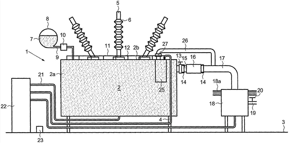
-图1是防火装置的示意图;- Figure 1 is a schematic diagram of the fire protection device;
-图2是图1的详细视图;- Figure 2 is a detailed view of Figure 1;
-图3是与若干个变压器相关联的防火装置的示意图;- Figure 3 is a schematic diagram of a fire protection device associated with several transformers;
-图4示出图1的变化形式;- Figure 4 shows a variant of Figure 1;
-图5示出图1的变化形式;- Figure 5 shows a variant of Figure 1;
-图6是击穿元件的截面图;- Figure 6 is a cross-sectional view of the breakdown element;
-图7是图6的放大局部图;- Figure 7 is an enlarged partial view of Figure 6;
-图8是相应于图6从上部的视图;- Figure 8 is a view from the top corresponding to Figure 6;
-图9是相应于图6的从下部的视图;- Figure 9 is a view from below corresponding to Figure 6;
-图10是具有竖直减压室的防火装置的示意图;- Figure 10 is a schematic diagram of a fire protection installation with a vertical decompression chamber;
-图11是相应于图10的整体视图;以及- Figure 11 is an overall view corresponding to Figure 10; and
-图12和图13示出图1的变化形式。- Figures 12 and 13 show variants of Figure 1 .
具体实施方式 Detailed ways
如图所例示,变压器1包括借助支脚4搁置于地面3上的箱2,并由绝缘体6所围绕的电线5供应电能。箱2包括箱体2a和箱盖2b。As illustrated, the transformer 1 comprises a
箱2填充有冷却液7,例如介电油。为确保冷却液7在箱2内保持恒定高度,变压器1配备有由管9连接到箱2的油枕8。The
管9设置有自动止回阀10,其一探测到流体7的快速流动就关闭管9。因此,在箱2减压过程中,管9内压力的突降造成流体7开始流动,其流动通过自动止回阀10的阻挡动作被快速地阻止。因此防止油枕8内所容纳的流体7排空。The tube 9 is provided with an
箱2也配备有一条或多条火警探测线缆11。在所提出的实施方式中,火警探测线缆11装配于箱2上方,并受到搁置于箱盖2b上的块体12的支撑。数厘米的距离将线缆11和箱盖2b分离开。线缆11可包括由具有低熔点的合成膜片所隔离的两条电线,该两条电线在该膜片熔化时接触。线缆11可沿箱2边缘附近的矩形路径布置。The
箱2可包括传感器,也称作Buchholz,用于探测是否存在来自冷却液的蒸气,其装配于箱2的高点,一般位于管9上。电绝缘体的击穿导致蒸气从箱2内的流体7排放出。蒸气式传感器能够用来以一定延迟的方式探测电绝缘体的击穿。
变压器1由电源柜供电,未示出,该电源柜包括诸如断路器的电源切断装置并配备有触发式传感器。The transformer 1 is powered by a power cabinet, not shown, which includes a power cut-off device such as a circuit breaker and is equipped with a trigger sensor.
该防止装置包括装配到箱2出口的阀13,该出口配置于箱体2a的高点;击穿元件15,其断裂用来无延迟地探测由于变压器电绝缘体的击穿所引起的压力变化;以及两个吸振弹性套筒14,其中一个弹性套筒配置于阀13和击穿元件15之间。该防止装置还包括具有大于击穿元件15的直径的减压室16,其装配在击穿元件15的下游;由贮存器18所支撑的排出管17,贮存器18用于在击穿元件15断裂之后收集来自箱2的流体并用于将液体成分从气体成分中分离出。管17装配于减压室16和贮存器18之间。另一弹性套筒14装配于减压室16和管17之间。This prevention device consists of a
贮存器18可配备有冷却鳍片18a。贮存器18配备有用于排放由油所散发出的气体的管19。管19可临时地连接到可移动式容器,以排空贮存器18。因此,箱2立即得到减压并在以后部分地排空到油枕8中。击穿元件15可用于在低于1巴的预定压力下打开,例如在0.6巴和1.6巴之间,优选在0.8巴和1.4巴之间。The
在管19内配置阀20以防止空气内的氧气进入,氧气可支持贮存器18和箱2内的气体和油燃烧,并防止气体和液体不受控制地排出。阀20可为手动式的和用手动控制的机械化的。阀20总是关闭着以保持该贮存器密封,除非在贮存器18被排空其内存在的气体,或者在实施气体净化的时候。A
箱2包括通过将诸如氮气的惰性气体注入箱2底部内来冷却流体7的装置。该惰性气体存储在加压贮存器内,该减压贮存器配备有阀、膨胀阀或减压器以及将气体运送到箱2的软管21。该加压贮存器放置在机柜22内。The
线缆11、击穿元件15、蒸气式传感器、触发式传感器、阀13和柱塞阀20都连接到用于监测该装置的操作的控制单元23。控制单元23配备有从各个传感器接收信号并能够发射控制信号--尤其是阀20的--的信息处理装置。The
在正常操作中,阀13打开,且击穿元件15完整无损,即关闭着。阀20也关闭着。为了维护操作,在变压器1关闭情况下,阀13也可关闭。弹性套筒14能够吸收变压器1在操作时和短路期间所产生的振动,以防止该振动传递到其它组件,特别是击穿元件15。减压室16能够在击穿元件15断裂时,因极端减少的压头损失,使压力急剧下降。In normal operation, the
当变压器1出现电路故障后击穿元件15紧接着断裂时,箱2内的压力降低。气体和/或液体的喷流流经击穿元件15并溢流进减压室16内,然后流入管17到达贮存器18。减压室16的作用能够证明在击穿元件15断裂后紧接着的最初几毫秒内特别重要。When the
以后,可将诸如氮气的惰性气体注入箱2底部内,以吹净可能残留在箱2内的可燃气体,并冷却变压器的炽热部件以阻止气体产生。惰性气体的注入可在击穿元件15断裂后的几分钟至数小时内启动;优选提供充分的沉淀时间,以使气体和液体合适地分离。另外,可能会等待贮存器18及其所含物冷却。所述的可燃气体被排空到贮存器18。可移动式容器可连接到管19,以在阀20打开后接收贮存器18内存在的流体。贮存器18可用惰性气体净化。然后能够对击穿元件15进行替换。为安全原因,用于惰性气体的贮存器用来能够使注射惰性气体持续大约45分钟时间段,这对于通过搅动油来冷却油和炽热部件、并因此防止通过分解油而产生气体,可证明是有用的。Later, an inert gas such as nitrogen can be injected into the bottom of the
变压器1可配备有一个或多个有载式调压开关25,其作用为所述变压器1和它所连接的电源网之间的界面,以不论供应给该电源网的电流是否变化都提供恒定电压。有载式调压开关25通过排出管26连接到用于排出的管17。这是因为有载式调压开关25也由可燃冷却液冷却。由于其高机械强度,有载式调压开关的爆炸是极其强烈的,并能够伴随有燃烧着的冷却液喷流的喷出。管26配备有减压元件27,其能够在如果发生短路并因此在有载式调压开关25内部出现过大压力时裂开。因此防止了所述的有载式调压开关25的箱爆炸。依据本发明,提供一种极其快速地探测绝缘体内的击穿并同时采取行动以减小所引发的后果的变压器爆炸防止装置。结果,变压器、有载式调压开关和衬套得到挽救,且与该绝缘故障相关联的损坏降至最小。The transformer 1 may be equipped with one or more OLTCs 25, which act as an interface between said transformer 1 and the mains to which it is connected, to provide a constant Voltage. The on-
如图2所示,减压室16搁置于由固定到箱2箱体2a的支架29所支撑的四个减震器28上。因此,一方面在变压器1正常操作期间的振动和减压室16之间产生机械式隔离,另一方面在变压器1于绝缘体内击穿期间的变形与减压室16之间也产生机械式隔离。As shown in FIG. 2 , the
在图3所例示的实施方式中,若干个相邻的变压器1连接到贮存器18。换言之,用于不同变压器的若干个防止装置能够具有一个共用的贮存器18。这在可用空间受到限制的有限区域内证明特别有利。In the embodiment illustrated in FIG. 3 , several adjacent transformers 1 are connected to the
在图4所例示的实施方式中,该防止装置附加地包括由管连接到贮存器18的真空泵30。贮存器18可例如通过氮气膨胀配备冷却系统18b。当该防止装置被置于操作时,真空泵30被启动并在贮存器18内产生部分真空,然后它就被停止。在击穿元件15断裂后,来自箱2的能够存储于贮存器18内的大量气体增加到最大相等压力。因此能够便于减压。该贮存器可为减小的容积,因此产生空间增益。In the embodiment illustrated in FIG. 4 , the preventing means additionally comprise a
在图5所例示的实施方式中,该防止装置附加地包括气泵31,其连接到管17或贮存器18并连接到承担压力的瓶体32内。在击穿元件15断裂后,且存在气体冷却所用充分时间段所用的流动,气泵31被启动并泵抽贮存器18内存在的气体。因此贮存器18能够被排空其内所容纳的气体,所述气体能够为惰性气体和可燃气体的混合物。在气泵31停止后,瓶体32能够被容易拆除并远距离地运输。这种实施方式特别适于安装在矿井或隧道里的变压器。In the embodiment illustrated in FIG. 5 , the prevention device additionally comprises an
如图6至9所示,击穿元件15是凸状拱式圆形形状,并用于安装到箱2的夹在两个盘形凸缘33、34之间的输出孔,未示出。释放元件15包括薄金属片形式的保持部件35,例如由不锈钢、铝或铝合金制成。保持部件35的厚度可介于0.05mm到0.25mm之间。As shown in FIGS. 6 to 9 , the
保持部件35具有将它划分成若干部分的径向沟槽36。径向沟槽36形成于保持部件35厚度内的凹槽里,使得通过在保持部件35中央将保持部件35撕裂就会击穿,并且这种击穿发生时没有碎片,从而防止释放元件15的碎片脱落并由通过释放元件15的流体移动以及冒着损坏定位于下游的管的风险。The retaining
保持部件35在中央附近设置有为每个沟槽36配置一个的很小直径的通孔37。换言之,若干个孔37成六角形地配置。孔37形成低强度的启动部位,并确保撕裂在保持部件35的中央发动。在每个沟槽36形成至少一个孔37,确保沟槽36将同时分离,从而提供最大可能的通道截面。作为变化形式,不同于六个的多个沟槽36,和/或每个沟槽36若干个孔37,均可设想到。不可渗透的涂层50能够阻挡孔37。The holding
释放元件15的断裂压力是由--特别是由--孔37的直径和位置、沟槽36的深度、以及形成保持部件35的厚度和组成物决定的。优选地,沟槽36形成于保持部件35的整个厚度上。保持部件35的其余部分可具有恒定厚度。The breaking pressure of the
两个相邻沟槽36形成三角形39,三角形39在击穿期间因孔37之间的材料撕裂而将会和相邻的三角形分离,并将通过折叠而朝向下游方向变形。三角形39折叠而没有撕裂,从而防止所述三角形39脱落,三角形39脱落是能够损坏下游管或扰乱下游管内的流动,因此增加压头损失并减缓上游侧的减压过程。沟槽36的数量也视保持部件15的直径而定。Two
配置于凸缘33下游的凸缘34具有钻透它的径向孔,保护管41配置进它的径向孔内。该击穿探测器包括固定到保持部件35位于下游侧并配置成环的电线42。电线42延伸进保护管41内直到连接单元43。电线42几乎越过保持部件15整个直径延伸,且电线的一部分42a在沟槽36的一个侧面上且平行于所述沟槽进行配置,而电线的另一部分42b平行于所述沟槽36径向地配置于该相同沟槽36的另一侧面上。两个电线部分42a、42b之间的距离较小。这个距离可小于分隔两个孔37的最大距离,使得电线42在孔37之间穿过。The
电线42由保护膜覆盖,该保护膜作用为保护它不受腐蚀和将它粘结到保持部件35的下游面。对这种膜的组成物也要进行选择以避免修改击穿元件15的击穿压力。这种膜可由脆化的聚酰胺制成。击穿元件的断裂必定地导致电线42切断。借助中断流经电线42的电流或借助电线42两个端部之间的电压差,能够以极其简单可靠的方式探测到这种切断。The
击穿元件15还包括配置于凸缘33和34之间的金属片形式的加强部件44,例如由不锈钢、铝和铝合金制成的。加强部件44的厚度可介于0.2mm和1mm之间。The
加强部件44包括多个凸瓣,例如五个,该多个凸瓣由形成于它们整个厚度上的径向沟槽45分隔。该凸瓣连接到外环形边缘--圆的弧形形式的沟槽46,其形成于各凸瓣除邻接凸瓣附近外的整个厚度上,因此给予该凸瓣轴向地变形的能力。该凸瓣之一例如通过焊接连接到中央多边形47。多边形47封盖该凸瓣中央,并搁置在固定到其余凸瓣且相对该凸瓣轴向地偏置的钩件48上,使得多边形47轴向地配置于该凸瓣和对应构件48之间。多边形47可接触钩件48的底部以在其上轴向地下压。加强部件44提供沿一个方向的良好轴向强度和沿另一方向--击穿元件15的断裂方向--的非常低的轴向强度。当变压器1的箱2内的压力低于减压室16内的时,如果为填充变压器1在箱2内产生部分真空可能会出现这种情况,加强部件44就特别有用。The
在保持部件35和加强部件44之间,可配置包括薄膜50的不可渗透的部件49,薄膜50由诸如基于聚四氟乙烯的不可渗透的合成材料形成,且各面上由预剪切的合成材料所形成、防止薄膜50被保持部件35和加强部件44穿孔的厚膜51围绕。各厚膜51可包括例如基于具有0.1mm到0.3mm量级厚度的聚四氟乙烯的合成材料。厚膜51可预剪切成圆的约330°弧形的形式。厚膜51可具有0.005mm到0.1mm的量级的厚度。Between the retaining
击穿元件15提供沿一个方向的良好阻抗性、沿另一方向的校准过的阻抗性、优良的不可渗透性和断裂时的低度滞后。The
为改进不可渗透性,击穿元件15可包括配置于凸缘33与保持部件35之间的垫圈52、和凸缘34与加强部件44之间的垫圈53。垫圈52和53可由基于聚四氟乙烯的材料制成。To improve the impermeability, the
另外,可提供用于冷却该防止装置内的流体的装置。该冷却装置可包括管17和/或贮存器18上的鳍片、用于贮存器18的空调、和/或储备的液化气体,例如氮气,其膨胀能够冷却贮存器18。Additionally, means for cooling the fluid within the containment device may be provided. The cooling means may include fins on the
在图10和图11的实施方式中,该防止装置大致竖直地配置于例如箱2的箱盖2b上。减压室16包括竖直轴向筒体,该竖直轴向筒体在其端部封闭同时连接到击穿元件15,具有比击穿元件15直径大的直径,且装配于击穿元件15的下游。减压室16也形成收集贮存器。管19连接到减压室16的筒体的上部区域。管54连接到减压室16的筒体的下部区域,用于移除液体。这种实施例特别紧凑,大多数的该防止装置都定位于箱2上方。In the embodiment of FIGS. 10 and 11 , the preventing device is arranged approximately vertically on, for example, the
在一个有利变化形式中,管54连接到油枕8--参见图10的虚线所示。油枕8的有用容积,即未被液体占用的部分,可用于容纳来自减压室16的液体。附加击穿元件61可配置于减压室16和油枕8之间的管54上。该附加击穿元件61可校准在比减压室16上游的击穿元件15高的击穿压力上。In an advantageous variant, the
当操作时,管54的压头损失在击穿元件15击穿期间给予自动止回阀10关闭的时间。油枕8收集了来自减压室16的液体,自动止回阀10关闭。When in operation, the head loss of the
如图11所例示,减压室16连接到定位于管26延伸部上的管17中。管17连接到油枕8内。As illustrated in FIG. 11 , the
在图12所示的实施方式中,该防止装置包括装配于箱2出口的阀13,该出口配置于位于箱体2a高度的大约一半或三分之二处的箱体2a的点。管17从减压室16向上弯曲,并包括在高于变压器1线圈的水平处所配置的顶部17a。举例而言,顶部17a的底部能够定位于比该线圈顶端高约20mm处。因此,该部分的排空和减压能够使该线圈保持被浸没且所生成的绝缘也被保留。In the embodiment shown in Fig. 12, the prevention means comprise a
管9配备有配置于自动止回阀10和箱2的箱盖2b之间的气体探测器55。管56连接管9和管7的顶部17a。管56在气体探测器55和自动止回阀10之间连接到管9。在管56上配置有手动阀57,除维护操作期间外保持在打开位置;由控制单元23控制的电磁阀58,在正常服务期间位于关闭位置,在击穿元件15进行压力释放后位于打开位置,以回收管9内存在的可燃气体。The pipe 9 is equipped with a
另外,具有油绝缘的绝缘套管6也配备有减压元件59,其连接到与管17连接的管60。减压元件59可为相似于减压元件15的结构且配适成合适尺寸。因此,该箱、该绝缘套管和该有载式调压开关可配备有减压元件,用于提高保存它们完整的可能性。In addition, the insulating
在图13所示的实施方式中,该防止装置包括装配到箱2出口的阀13,该出口配置于箱体2a的低点。管17象前述实施方式一样,从减压室16向上弯曲,并包括顶部17a。In the embodiment shown in Figure 13, the means of prevention comprise a
此种保护系统比较经济,独立于邻接装置,尺寸紧凑且无需维护。This protection system is economical, independent of adjacent devices, compact in size and maintenance-free.
该控制单元也能够连接到次级传感器,例如火警探测器、蒸气式探测器(Buchholz),及连接到电源柜触发传感器,用于若爆炸防止系统失效就触发灭火工序。The control unit can also be connected to secondary sensors, such as fire detectors, vapor detectors (Buchholz), and to trigger sensors in the power cabinet for triggering the fire extinguishing process if the explosion prevention system fails.
依据本发明,提供一种对变压器组件几乎不需要修改的变压器爆炸防止装置,其装置极其快速地探测绝缘体击穿并同时采取行动以减小所生成的后果,包括在密闭空间内亦如此。这具有防止油浸电容器爆炸和发生火灾的效果,降低和变压器短路、有载式调压开关和绝缘套管相关的损害。According to the present invention, there is provided a transformer explosion arrester requiring little modification to the transformer components, which device detects insulation breakdown extremely quickly and at the same time takes action to reduce the resulting consequences, including in confined spaces. This has the effect of preventing oil capacitor explosions and fires, reducing damage associated with short circuits in transformers, tap taps and bushings.
Claims (11)
Applications Claiming Priority (2)
| Application Number | Priority Date | Filing Date | Title |
|---|---|---|---|
| FR0506661 | 2005-06-29 | ||
| FR0506661A FR2888034B1 (en) | 2005-06-29 | 2005-06-29 | DEVICE FOR PREVENTING THE EXPLOSION OF AN ELECTRICAL TRANSFORMER |
Related Parent Applications (1)
| Application Number | Title | Priority Date | Filing Date |
|---|---|---|---|
| CN2006800008825A Division CN101031985B (en) | 2005-06-29 | 2006-06-22 | Devices for Protection against Transformer Explosions |
Publications (2)
| Publication Number | Publication Date |
|---|---|
| CN102768896A true CN102768896A (en) | 2012-11-07 |
| CN102768896B CN102768896B (en) | 2015-04-01 |
Family
ID=35788317
Family Applications (2)
| Application Number | Title | Priority Date | Filing Date |
|---|---|---|---|
| CN201210229042.3A Active CN102768896B (en) | 2005-06-29 | 2006-06-22 | Device for preventing explosion of transformer |
| CN2006800008825A Active CN101031985B (en) | 2005-06-29 | 2006-06-22 | Devices for Protection against Transformer Explosions |
Family Applications After (1)
| Application Number | Title | Priority Date | Filing Date |
|---|---|---|---|
| CN2006800008825A Active CN101031985B (en) | 2005-06-29 | 2006-06-22 | Devices for Protection against Transformer Explosions |
Country Status (28)
| Country | Link |
|---|---|
| US (1) | US7317598B2 (en) |
| EP (2) | EP1908085B1 (en) |
| JP (2) | JP5054683B2 (en) |
| KR (2) | KR101278105B1 (en) |
| CN (2) | CN102768896B (en) |
| AP (1) | AP2474A (en) |
| AR (1) | AR054520A1 (en) |
| AT (1) | ATE520134T1 (en) |
| AU (1) | AU2006264846B2 (en) |
| BR (1) | BRPI0613852B1 (en) |
| CA (1) | CA2611221C (en) |
| CY (2) | CY1111987T1 (en) |
| DK (2) | DK1908085T3 (en) |
| EA (1) | EA012010B1 (en) |
| EG (1) | EG25269A (en) |
| ES (2) | ES2393531T3 (en) |
| FR (2) | FR2888034B1 (en) |
| JO (1) | JO2640B1 (en) |
| MX (1) | MX2008000083A (en) |
| MY (1) | MY149205A (en) |
| NZ (1) | NZ564383A (en) |
| PL (2) | PL1908085T3 (en) |
| PT (2) | PT1908085E (en) |
| SI (1) | SI1908085T1 (en) |
| TW (2) | TWI404084B (en) |
| UA (1) | UA90520C2 (en) |
| WO (1) | WO2007003736A1 (en) |
| ZA (1) | ZA200710988B (en) |
Cited By (2)
| Publication number | Priority date | Publication date | Assignee | Title |
|---|---|---|---|---|
| CN104867670A (en) * | 2015-05-11 | 2015-08-26 | 中国西电电气股份有限公司 | Oil immersed type current transformer with explosion-proof device |
| CN116031045A (en) * | 2022-12-29 | 2023-04-28 | 扬州永鼎电气科技有限公司 | Oil immersed transformer with explosion-proof function and working method thereof |
Families Citing this family (58)
| Publication number | Priority date | Publication date | Assignee | Title |
|---|---|---|---|---|
| FR2888034B1 (en) * | 2005-06-29 | 2010-10-08 | Philippe Magnier | DEVICE FOR PREVENTING THE EXPLOSION OF AN ELECTRICAL TRANSFORMER |
| BRPI0608718B1 (en) * | 2005-11-16 | 2017-06-27 | Ctr Manufacturing Industries Limited | METHOD AND DEVICE FOR PREVENTION AND PROTECTION OF ELECTRIC TRANSFORMER AGAINST EXPLOSION AND FIRE |
| KR100754740B1 (en) * | 2006-06-01 | 2007-09-03 | 현대중공업 주식회사 | Enclosure burst protection device of transformer |
| MX2009004511A (en) * | 2006-10-27 | 2009-05-12 | Philippe Magnier Llc | Device for prevention against the explosion of an electric transformer member. |
| US8044307B2 (en) * | 2006-12-28 | 2011-10-25 | Abb Technology Ltd. | Power transformer/reactor |
| US7451012B2 (en) * | 2007-02-21 | 2008-11-11 | Gree Electric Applicances Inc. Of Zhuhai | Fault electric arc protection circuits and method for detecting fault electric arc |
| CN101911222B (en) * | 2008-01-01 | 2013-08-28 | Ctr工业制造有限公司 | System and method for preventing, protecting OLTC from fire and/or transformer from explosion |
| CA3101888A1 (en) | 2008-05-16 | 2009-11-19 | REG Life Sciences, LLC | Methods and compositions for producing hydrocarbons |
| DE102008027274B3 (en) * | 2008-06-06 | 2009-08-27 | Maschinenfabrik Reinhausen Gmbh | Power transformer with tap changer |
| US8710946B2 (en) * | 2008-09-17 | 2014-04-29 | General Electric Company | Rupture resistant system |
| US9159482B2 (en) | 2008-09-17 | 2015-10-13 | General Electric Company | Rupture resistant tank system |
| US8717134B2 (en) * | 2008-09-17 | 2014-05-06 | General Electric Company | System with directional pressure venting |
| BRPI0822784A8 (en) * | 2008-09-19 | 2017-12-26 | Abb Technology Ag | MANUFACTURING GROUP |
| WO2010040379A1 (en) * | 2008-10-06 | 2010-04-15 | Abb Technology Ag | A transformer assembly |
| US8097439B2 (en) | 2008-10-07 | 2012-01-17 | Ls9, Inc. | Methods and compositions for producing fatty aldehydes |
| CN105154380B (en) | 2008-10-28 | 2018-11-09 | Reg生命科学有限责任公司 | Method and composition for generating fatty alcohol |
| DE102009035699A1 (en) * | 2009-07-30 | 2011-02-10 | Maschinenfabrik Reinhausen Gmbh | Arrangement of a tap changer on a control transformer |
| WO2011100667A1 (en) | 2010-02-14 | 2011-08-18 | Ls9, Inc. | Surfactant and cleaning compositions comprising microbially produced branched fatty alcohols |
| US20110273255A1 (en) * | 2010-05-10 | 2011-11-10 | Robert Samuel Thompson | Endoskeletal transformer tank |
| CN101975881B (en) * | 2010-08-25 | 2012-05-23 | 太原理工大学 | Diagnosis and early warning device of faults of mine explosion-proof dry type transformers |
| FR2971357B1 (en) * | 2011-02-08 | 2013-02-15 | Philippe Magnier Llc | DEVICE FOR PREVENTING THE EXPLOSION OF AN ELECTRICAL TRANSFORMER PROVIDED WITH A LIQUID INDICATOR |
| FR2973153A1 (en) * | 2011-03-21 | 2012-09-28 | Philippe Magnier Llc | DEVICE FOR PREVENTING EXPLOSION OF A SUPPLY CHANGER WITH A BREAKING ELEMENT |
| US8573513B2 (en) * | 2011-05-27 | 2013-11-05 | GM Global Technology Operations LLC | Fuel system inlet check valve with flame arresting feature |
| PH12014500885A1 (en) | 2011-10-11 | 2021-06-02 | Transf Protector Corporation | Depressurization system for an electrical transformer |
| FR2989235B1 (en) * | 2012-04-06 | 2014-03-14 | Schneider Electric Ind Sas | ISOLATION CONTROL SYSTEM FOR SECURE ELECTRICAL NETWORK |
| UA110750C2 (en) * | 2012-05-01 | 2016-02-10 | Ктр Меньюфекчурінґ Індастріз Лімітед | A device for detecting leakage |
| US9453686B2 (en) * | 2013-08-20 | 2016-09-27 | Shun-Fu International Electrical Co., Ltd. | Self-cooling energy saver |
| EP2899728B2 (en) * | 2014-01-22 | 2019-11-13 | ABB Schweiz AG | A device comprising a high voltage apparatus including a fluid and equipment for detecting one or more physical properties of the fluid |
| WO2015164854A1 (en) * | 2014-04-25 | 2015-10-29 | Sentry Depressurization Systems, Inc. | Fluid control systems for electrical transformers |
| FR3023962B1 (en) * | 2014-07-17 | 2017-11-24 | Soc Nat Des Chemins De Fer Francais Sncf | VACUUM ELECTRIC SUBMERSIBLE TRANSFORMER |
| KR101561638B1 (en) | 2015-06-22 | 2015-10-20 | (주)국제전기 | Transformer Explosion Prevention and damage detection device |
| EP3109871B1 (en) | 2015-06-25 | 2020-08-19 | ABB Power Grids Switzerland AG | Transformer arrangement for controlling pressure in a liquid-filled transformer |
| CN105097190B (en) * | 2015-09-29 | 2017-04-12 | 深圳市旭明消防设备有限公司 | Charged full-automatic flame failure protection device and protection method for oil immersed transformer |
| EA039116B1 (en) * | 2017-03-06 | 2021-12-07 | В. К. Вакшор | TRANSFORMER FIRE DETECTION AND EXPLOSION PREVENTION DEVICE AND CORRESPONDING METHOD |
| US10748682B2 (en) * | 2017-05-31 | 2020-08-18 | Abb Schweiz Ag | Surge arrester system and circuit breaker system |
| US10586645B2 (en) * | 2017-08-14 | 2020-03-10 | Abb Power Grids Switzerland Ag | Transformer systems and methods for operating a transformer system |
| EP3718385B1 (en) * | 2017-12-30 | 2024-08-21 | Hitachi Energy Ltd | System for sensor utilization in a transformer cooling circuit |
| BR102018000375A2 (en) * | 2018-01-08 | 2019-07-16 | Eduardo Pedrosa Santos | INTEGRATED CONTROL, SUPERVISION AND MONITORING SYSTEM OF POWER TRANSFORMERS EQUIPPED WITH LOAD SHUNT SWITCHES. |
| KR101886868B1 (en) * | 2018-02-20 | 2018-08-08 | 이춘업 | Explosion-proof equipment |
| KR101865105B1 (en) * | 2018-04-09 | 2018-06-08 | 대흥전력기술 주식회사 | Gas pressure falling device and mounting method therefor |
| US10854368B2 (en) | 2018-05-23 | 2020-12-01 | Abb Power Grids Switzerland Ag | Electrical equipment with rupture oil deflector |
| US11946552B2 (en) | 2018-07-26 | 2024-04-02 | Sentry Global Solutions, Inc. | Rapid depressurization and explosion prevention system for electrical transformers |
| KR101967317B1 (en) * | 2019-03-08 | 2019-04-09 | 안호재 | Portable explosion-proof type transformer |
| CN110829356B (en) * | 2019-12-12 | 2025-05-16 | 河南及时星应急救援装备有限公司 | An electrical explosion-proof isolation protection device |
| CN111326315B (en) * | 2020-03-10 | 2021-03-12 | 山东省产品质量检验研究院 | Transformer electric appliance cabinet |
| US12626850B2 (en) | 2020-09-18 | 2026-05-12 | Hitachi Energy Ltd | Housing part, electrical system and operating method |
| CN112542298B (en) * | 2020-12-02 | 2022-03-11 | 北京中瑞和电气有限公司 | Explosion-proof pressure relief transformer |
| CN112712973A (en) * | 2021-01-13 | 2021-04-27 | 赖金兰 | Intelligent power transformer capable of automatically adjusting current |
| CN113436835B (en) * | 2021-06-25 | 2023-02-17 | 广东电网有限责任公司 | Power transformer and explosion-proof method thereof |
| KR102456798B1 (en) * | 2022-08-29 | 2022-10-24 | 유한회사 대영글로벌 | Oil-immersed transformer oil pit device for power |
| CN117129133B (en) * | 2023-10-27 | 2024-01-02 | 南京中鑫智电科技有限公司 | Online monitoring method and system for high-voltage casing pressure |
| US12259050B1 (en) | 2024-02-20 | 2025-03-25 | Philippe Magnier Llc | Technologies for preventing the explosion of electrical transformers |
| WO2025178856A1 (en) | 2024-02-20 | 2025-08-28 | Philippe Magnier Llc | Technologies for preventing the explosion of electrical transformers |
| US20250305912A1 (en) * | 2024-03-30 | 2025-10-02 | Anthony E Eason | Substation power transformer monitoring system for ensuring cooling system integrity by isolating damaged radiator sections |
| CN118136375B (en) * | 2024-04-19 | 2024-11-15 | 河北远大电子有限公司 | High-efficient heat dissipation formula transformer |
| KR102909548B1 (en) | 2024-06-24 | 2026-01-07 | 정종기 | Pressure control apparatus of transformer |
| CN118737638B (en) * | 2024-08-31 | 2024-12-06 | 浙江尔格科技股份有限公司 | Water route area automatic depressurization's oil water cooler |
| CN120895367B (en) * | 2025-09-08 | 2026-03-20 | 立尔威电气(江苏)有限公司 | An oil-immersed transformer with circulating heat dissipation |
Citations (4)
| Publication number | Priority date | Publication date | Assignee | Title |
|---|---|---|---|---|
| EP0238475A1 (en) * | 1986-02-20 | 1987-09-23 | ELIN-UNION Aktiengesellschaft für elektrische Industrie | Fire extinguishing apparatus |
| CN1165581A (en) * | 1995-09-28 | 1997-11-19 | 菲利普·马格尼尔 | Method and device for preventing transformer explosion and fire |
| CN1346499A (en) * | 1999-03-22 | 2002-04-24 | 菲利普·马格尼尔 | Devices for Preventing Explosion of Electronic Transformers |
| CN2532566Y (en) * | 2002-01-12 | 2003-01-22 | 王延敬 | Explosion-proof fire-extinguishing device for oil-immersed transformer |
Family Cites Families (24)
| Publication number | Priority date | Publication date | Assignee | Title |
|---|---|---|---|---|
| DE437274C (en) * | 1926-11-13 | Bbc Brown Boveri & Cie | Safety valve with liquid seal for oil transformers | |
| GB688952A (en) * | 1950-03-31 | 1953-03-18 | British Thomson Houston Co Ltd | Improvements in and relating to liquid-immersed apparatus |
| FR1355777A (en) | 1963-02-08 | 1964-03-20 | Comp Generale Electricite | Improvements to cooling devices for electrical appliances |
| DE2624882A1 (en) | 1976-06-03 | 1977-12-15 | Transformatoren Union Ag | Overpressure protection for insulant filled machines - has cover liftable by excessive pressure after which cover is replaced and sealed |
| US4117525A (en) | 1977-09-09 | 1978-09-26 | Electric Power Research Institute, Inc. | Overpressure protection for vaporization cooled electrical apparatus |
| JPS56134713A (en) * | 1980-03-26 | 1981-10-21 | Toshiba Corp | Oil filled electrical appliance |
| JPS577909A (en) * | 1980-06-18 | 1982-01-16 | Toshiba Corp | Oil filled electric equipment |
| JPS6042718U (en) * | 1983-09-01 | 1985-03-26 | 北芝電機株式会社 | Oil spill prevention device for tap changer under load |
| JPH046181Y2 (en) * | 1984-10-13 | 1992-02-20 | ||
| JPH01248603A (en) | 1988-03-30 | 1989-10-04 | Mitsubishi Electric Corp | Pressure discharging device of gas insulation electric machine |
| JPH033305A (en) * | 1989-05-31 | 1991-01-09 | Meidensha Corp | Safety device for enclosed electrical machinery and apparatus |
| US5415033A (en) * | 1990-08-30 | 1995-05-16 | Vista Research, Inc. | Simplified apparatus for detection of leaks in pressurized pipelines |
| JPH0627932Y2 (en) * | 1991-04-17 | 1994-07-27 | 愛知電機株式会社 | Oil level drop prevention device for tap changer under load |
| JPH0529155A (en) * | 1991-07-22 | 1993-02-05 | Hitachi Ltd | Stationary induction |
| FR2684248B1 (en) | 1991-11-22 | 1997-04-30 | Pioch Sa | ELECTRONIC APPARATUS FOR MEASURING AND PROTECTING THE OPERATION OF THE OIL TRANSFORMER. |
| WO1994028566A1 (en) | 1993-05-20 | 1994-12-08 | University Of Technology, Sydney | Partial discharge passive monitor |
| AT403019B (en) | 1994-12-23 | 1997-10-27 | Franz Ing Stuhlbacher | DEVICE FOR PRODUCING STRETCH MATERIAL |
| JPH10149922A (en) * | 1996-11-19 | 1998-06-02 | Toshiba Fa Syst Eng Kk | Oil-filled electrical equipment |
| CZ292922B6 (en) * | 2001-07-23 | 2004-01-14 | Josef Ing. Altmann | Device for reducing contamination of transformer charges with gases and water |
| FR2831342B1 (en) * | 2001-10-22 | 2003-12-19 | Alstom | PROTECTION SYSTEM FOR A THREE-PHASE DISTRIBUTION TRANSFORMER INSULATED IN A LIQUID DIELECTRIC COMPRISING A PHASE DISCOVER SWITCH |
| TWM251268U (en) * | 2004-01-29 | 2004-11-21 | Tatung Co | Amorphous iron core air-insulation transformer |
| US7155347B2 (en) * | 2004-07-19 | 2006-12-26 | Fike Corporation | Pre-inerting method and apparatus for preventing large volume contained flammable fuels from exploding |
| JP4684721B2 (en) | 2005-04-14 | 2011-05-18 | 泰行 井上 | Conservator |
| FR2888034B1 (en) * | 2005-06-29 | 2010-10-08 | Philippe Magnier | DEVICE FOR PREVENTING THE EXPLOSION OF AN ELECTRICAL TRANSFORMER |
-
2005
- 2005-06-29 FR FR0506661A patent/FR2888034B1/en not_active Expired - Lifetime
-
2006
- 2006-06-15 TW TW095121363A patent/TWI404084B/en active
- 2006-06-15 TW TW101128735A patent/TWI470654B/en active
- 2006-06-20 JO JO2006186A patent/JO2640B1/en active
- 2006-06-22 PL PL06764812T patent/PL1908085T3/en unknown
- 2006-06-22 CA CA2611221A patent/CA2611221C/en active Active
- 2006-06-22 PL PL10011581T patent/PL2287865T3/en unknown
- 2006-06-22 KR KR1020077030606A patent/KR101278105B1/en active Active
- 2006-06-22 SI SI200631135T patent/SI1908085T1/en unknown
- 2006-06-22 EA EA200702653A patent/EA012010B1/en unknown
- 2006-06-22 CN CN201210229042.3A patent/CN102768896B/en active Active
- 2006-06-22 JP JP2008518898A patent/JP5054683B2/en active Active
- 2006-06-22 AT AT06764812T patent/ATE520134T1/en active
- 2006-06-22 DK DK06764812.1T patent/DK1908085T3/en active
- 2006-06-22 KR KR1020127028437A patent/KR101325252B1/en active Active
- 2006-06-22 EP EP06764812A patent/EP1908085B1/en active Active
- 2006-06-22 PT PT06764812T patent/PT1908085E/en unknown
- 2006-06-22 AP AP2008004302A patent/AP2474A/en active
- 2006-06-22 WO PCT/FR2006/001419 patent/WO2007003736A1/en not_active Ceased
- 2006-06-22 UA UAA200714778A patent/UA90520C2/en unknown
- 2006-06-22 ES ES10011581T patent/ES2393531T3/en active Active
- 2006-06-22 EP EP10011581A patent/EP2287865B1/en active Active
- 2006-06-22 CN CN2006800008825A patent/CN101031985B/en active Active
- 2006-06-22 PT PT10011581T patent/PT2287865E/en unknown
- 2006-06-22 DK DK10011581.5T patent/DK2287865T3/en active
- 2006-06-22 ES ES06764812T patent/ES2371221T3/en active Active
- 2006-06-22 BR BRPI0613852A patent/BRPI0613852B1/en active IP Right Grant
- 2006-06-22 US US11/473,339 patent/US7317598B2/en active Active
- 2006-06-22 MX MX2008000083A patent/MX2008000083A/en active IP Right Grant
- 2006-06-22 AU AU2006264846A patent/AU2006264846B2/en active Active
- 2006-06-22 NZ NZ564383A patent/NZ564383A/en unknown
- 2006-06-27 MY MYPI20063039A patent/MY149205A/en unknown
- 2006-06-27 AR ARP060102754A patent/AR054520A1/en active IP Right Grant
-
2007
- 2007-12-12 EG EGNA2007001407 patent/EG25269A/en active
- 2007-12-14 ZA ZA200710988A patent/ZA200710988B/en unknown
-
2010
- 2010-08-20 FR FR1003409A patent/FR2950469B1/en active Active
-
2011
- 2011-10-31 CY CY20111101036T patent/CY1111987T1/en unknown
- 2011-12-05 JP JP2011265834A patent/JP5759880B2/en active Active
-
2012
- 2012-11-21 CY CY20121101118T patent/CY1113390T1/en unknown
Patent Citations (4)
| Publication number | Priority date | Publication date | Assignee | Title |
|---|---|---|---|---|
| EP0238475A1 (en) * | 1986-02-20 | 1987-09-23 | ELIN-UNION Aktiengesellschaft für elektrische Industrie | Fire extinguishing apparatus |
| CN1165581A (en) * | 1995-09-28 | 1997-11-19 | 菲利普·马格尼尔 | Method and device for preventing transformer explosion and fire |
| CN1346499A (en) * | 1999-03-22 | 2002-04-24 | 菲利普·马格尼尔 | Devices for Preventing Explosion of Electronic Transformers |
| CN2532566Y (en) * | 2002-01-12 | 2003-01-22 | 王延敬 | Explosion-proof fire-extinguishing device for oil-immersed transformer |
Cited By (3)
| Publication number | Priority date | Publication date | Assignee | Title |
|---|---|---|---|---|
| CN104867670A (en) * | 2015-05-11 | 2015-08-26 | 中国西电电气股份有限公司 | Oil immersed type current transformer with explosion-proof device |
| CN116031045A (en) * | 2022-12-29 | 2023-04-28 | 扬州永鼎电气科技有限公司 | Oil immersed transformer with explosion-proof function and working method thereof |
| CN116031045B (en) * | 2022-12-29 | 2024-03-19 | 扬州永鼎电气科技有限公司 | Oil immersed transformer with explosion-proof function and working method thereof |
Also Published As
Similar Documents
| Publication | Publication Date | Title |
|---|---|---|
| KR101325252B1 (en) | Device for preventing the explosion of an electrical transformer | |
| CN1178233C (en) | Device for preventing electronic transformer from explosion | |
| US8351169B2 (en) | System and method for preventing, protecting OLTC from fire and/or transformer from explosion | |
| US20120200961A1 (en) | Electric transformer explosion prevention device provided with a liquid detector | |
| HK1176458B (en) | Device for preventing the explosion of an electrical transformer | |
| US12259050B1 (en) | Technologies for preventing the explosion of electrical transformers | |
| US20250378990A1 (en) | Technologies for preventing the explosion of electrical transformers | |
| WO2025178856A1 (en) | Technologies for preventing the explosion of electrical transformers | |
| HK1116294B (en) | Device for preventing the explosion of an electrical transformer |
Legal Events
| Date | Code | Title | Description |
|---|---|---|---|
| C06 | Publication | ||
| PB01 | Publication | ||
| C10 | Entry into substantive examination | ||
| SE01 | Entry into force of request for substantive examination | ||
| REG | Reference to a national code |
Ref country code: HK Ref legal event code: DE Ref document number: 1176458 Country of ref document: HK |
|
| C14 | Grant of patent or utility model | ||
| GR01 | Patent grant | ||
| REG | Reference to a national code |
Ref country code: HK Ref legal event code: GR Ref document number: 1176458 Country of ref document: HK |