CN102770080A - Systems, implants, tools and methods for treating pelvic disease - Google Patents
Systems, implants, tools and methods for treating pelvic disease Download PDFInfo
- Publication number
- CN102770080A CN102770080A CN2010800648584A CN201080064858A CN102770080A CN 102770080 A CN102770080 A CN 102770080A CN 2010800648584 A CN2010800648584 A CN 2010800648584A CN 201080064858 A CN201080064858 A CN 201080064858A CN 102770080 A CN102770080 A CN 102770080A
- Authority
- CN
- China
- Prior art keywords
- anchor
- tissue
- vaginal
- implant
- distal end
- Prior art date
- Legal status (The legal status is an assumption and is not a legal conclusion. Google has not performed a legal analysis and makes no representation as to the accuracy of the status listed.)
- Granted
Links
Images










Classifications
-
- A—HUMAN NECESSITIES
- A61—MEDICAL OR VETERINARY SCIENCE; HYGIENE
- A61B—DIAGNOSIS; SURGERY; IDENTIFICATION
- A61B1/00—Instruments for performing medical examinations of the interior of cavities or tubes of the body by visual or photographical inspection, e.g. endoscopes; Illuminating arrangements therefor
- A61B1/06—Instruments for performing medical examinations of the interior of cavities or tubes of the body by visual or photographical inspection, e.g. endoscopes; Illuminating arrangements therefor with illuminating arrangements
-
- A—HUMAN NECESSITIES
- A61—MEDICAL OR VETERINARY SCIENCE; HYGIENE
- A61B—DIAGNOSIS; SURGERY; IDENTIFICATION
- A61B90/00—Instruments, implements or accessories specially adapted for surgery or diagnosis and not covered by any of the groups A61B1/00 - A61B50/00, e.g. for luxation treatment or for protecting wound edges
- A61B90/30—Devices for illuminating a surgical field, the devices having an interrelation with other surgical devices or with a surgical procedure
-
- A—HUMAN NECESSITIES
- A61—MEDICAL OR VETERINARY SCIENCE; HYGIENE
- A61B—DIAGNOSIS; SURGERY; IDENTIFICATION
- A61B1/00—Instruments for performing medical examinations of the interior of cavities or tubes of the body by visual or photographical inspection, e.g. endoscopes; Illuminating arrangements therefor
- A61B1/00064—Constructional details of the endoscope body
- A61B1/00071—Insertion part of the endoscope body
- A61B1/0008—Insertion part of the endoscope body characterised by distal tip features
- A61B1/00082—Balloons
-
- A—HUMAN NECESSITIES
- A61—MEDICAL OR VETERINARY SCIENCE; HYGIENE
- A61B—DIAGNOSIS; SURGERY; IDENTIFICATION
- A61B1/00—Instruments for performing medical examinations of the interior of cavities or tubes of the body by visual or photographical inspection, e.g. endoscopes; Illuminating arrangements therefor
- A61B1/00064—Constructional details of the endoscope body
- A61B1/00071—Insertion part of the endoscope body
- A61B1/0008—Insertion part of the endoscope body characterised by distal tip features
- A61B1/00087—Tools
-
- A—HUMAN NECESSITIES
- A61—MEDICAL OR VETERINARY SCIENCE; HYGIENE
- A61B—DIAGNOSIS; SURGERY; IDENTIFICATION
- A61B1/00—Instruments for performing medical examinations of the interior of cavities or tubes of the body by visual or photographical inspection, e.g. endoscopes; Illuminating arrangements therefor
- A61B1/00064—Constructional details of the endoscope body
- A61B1/00071—Insertion part of the endoscope body
- A61B1/0008—Insertion part of the endoscope body characterised by distal tip features
- A61B1/00094—Suction openings
-
- A—HUMAN NECESSITIES
- A61—MEDICAL OR VETERINARY SCIENCE; HYGIENE
- A61B—DIAGNOSIS; SURGERY; IDENTIFICATION
- A61B1/00—Instruments for performing medical examinations of the interior of cavities or tubes of the body by visual or photographical inspection, e.g. endoscopes; Illuminating arrangements therefor
- A61B1/005—Flexible endoscopes
- A61B1/0051—Flexible endoscopes with controlled bending of insertion part
-
- A—HUMAN NECESSITIES
- A61—MEDICAL OR VETERINARY SCIENCE; HYGIENE
- A61B—DIAGNOSIS; SURGERY; IDENTIFICATION
- A61B1/00—Instruments for performing medical examinations of the interior of cavities or tubes of the body by visual or photographical inspection, e.g. endoscopes; Illuminating arrangements therefor
- A61B1/12—Instruments for performing medical examinations of the interior of cavities or tubes of the body by visual or photographical inspection, e.g. endoscopes; Illuminating arrangements therefor with cooling or rinsing arrangements
-
- A—HUMAN NECESSITIES
- A61—MEDICAL OR VETERINARY SCIENCE; HYGIENE
- A61B—DIAGNOSIS; SURGERY; IDENTIFICATION
- A61B1/00—Instruments for performing medical examinations of the interior of cavities or tubes of the body by visual or photographical inspection, e.g. endoscopes; Illuminating arrangements therefor
- A61B1/32—Devices for opening or enlarging the visual field, e.g. of a tube of the body
-
- A—HUMAN NECESSITIES
- A61—MEDICAL OR VETERINARY SCIENCE; HYGIENE
- A61B—DIAGNOSIS; SURGERY; IDENTIFICATION
- A61B17/00—Surgical instruments, devices or methods
- A61B17/00234—Surgical instruments, devices or methods for minimally invasive surgery
-
- A—HUMAN NECESSITIES
- A61—MEDICAL OR VETERINARY SCIENCE; HYGIENE
- A61B—DIAGNOSIS; SURGERY; IDENTIFICATION
- A61B17/00—Surgical instruments, devices or methods
- A61B17/02—Surgical instruments, devices or methods for holding wounds open, e.g. retractors; Tractors
- A61B17/0206—Surgical instruments, devices or methods for holding wounds open, e.g. retractors; Tractors with antagonistic arms as supports for retractor elements
-
- A—HUMAN NECESSITIES
- A61—MEDICAL OR VETERINARY SCIENCE; HYGIENE
- A61B—DIAGNOSIS; SURGERY; IDENTIFICATION
- A61B17/00—Surgical instruments, devices or methods
- A61B17/02—Surgical instruments, devices or methods for holding wounds open, e.g. retractors; Tractors
- A61B17/0293—Surgical instruments, devices or methods for holding wounds open, e.g. retractors; Tractors with ring member to support retractor elements
-
- A—HUMAN NECESSITIES
- A61—MEDICAL OR VETERINARY SCIENCE; HYGIENE
- A61B—DIAGNOSIS; SURGERY; IDENTIFICATION
- A61B17/00—Surgical instruments, devices or methods
- A61B17/04—Surgical instruments, devices or methods for suturing wounds; Holders or packages for needles or suture materials
- A61B17/0401—Suture anchors, buttons or pledgets, i.e. means for attaching sutures to bone, cartilage or soft tissue; Instruments for applying or removing suture anchors
-
- A—HUMAN NECESSITIES
- A61—MEDICAL OR VETERINARY SCIENCE; HYGIENE
- A61B—DIAGNOSIS; SURGERY; IDENTIFICATION
- A61B17/00—Surgical instruments, devices or methods
- A61B17/04—Surgical instruments, devices or methods for suturing wounds; Holders or packages for needles or suture materials
- A61B17/0469—Suturing instruments for use in minimally invasive surgery, e.g. endoscopic surgery
-
- A—HUMAN NECESSITIES
- A61—MEDICAL OR VETERINARY SCIENCE; HYGIENE
- A61B—DIAGNOSIS; SURGERY; IDENTIFICATION
- A61B17/00—Surgical instruments, devices or methods
- A61B17/04—Surgical instruments, devices or methods for suturing wounds; Holders or packages for needles or suture materials
- A61B17/06—Needles ; Sutures; Needle-suture combinations; Holders or packages for needles or suture materials
- A61B17/06066—Needles, e.g. needle tip configurations
- A61B17/06109—Big needles, either gripped by hand or connectable to a handle
-
- A—HUMAN NECESSITIES
- A61—MEDICAL OR VETERINARY SCIENCE; HYGIENE
- A61B—DIAGNOSIS; SURGERY; IDENTIFICATION
- A61B17/00—Surgical instruments, devices or methods
- A61B17/068—Surgical staplers, e.g. containing multiple staples or clamps
-
- A—HUMAN NECESSITIES
- A61—MEDICAL OR VETERINARY SCIENCE; HYGIENE
- A61B—DIAGNOSIS; SURGERY; IDENTIFICATION
- A61B17/00—Surgical instruments, devices or methods
- A61B17/08—Wound clamps or clips, i.e. not or only partly penetrating the tissue ; Devices for bringing together the edges of a wound
-
- A—HUMAN NECESSITIES
- A61—MEDICAL OR VETERINARY SCIENCE; HYGIENE
- A61B—DIAGNOSIS; SURGERY; IDENTIFICATION
- A61B17/00—Surgical instruments, devices or methods
- A61B17/10—Surgical instruments, devices or methods for applying or removing wound clamps, e.g. containing only one clamp or staple; Wound clamp magazines
-
- A—HUMAN NECESSITIES
- A61—MEDICAL OR VETERINARY SCIENCE; HYGIENE
- A61B—DIAGNOSIS; SURGERY; IDENTIFICATION
- A61B17/00—Surgical instruments, devices or methods
- A61B17/32—Surgical cutting instruments
- A61B17/3203—Fluid jet cutting instruments
-
- A—HUMAN NECESSITIES
- A61—MEDICAL OR VETERINARY SCIENCE; HYGIENE
- A61B—DIAGNOSIS; SURGERY; IDENTIFICATION
- A61B17/00—Surgical instruments, devices or methods
- A61B17/32—Surgical cutting instruments
- A61B17/3205—Excision instruments
- A61B17/3207—Atherectomy devices working by cutting or abrading; Similar devices specially adapted for non-vascular obstructions
- A61B17/320725—Atherectomy devices working by cutting or abrading; Similar devices specially adapted for non-vascular obstructions with radially expandable cutting or abrading elements
-
- A—HUMAN NECESSITIES
- A61—MEDICAL OR VETERINARY SCIENCE; HYGIENE
- A61B—DIAGNOSIS; SURGERY; IDENTIFICATION
- A61B17/00—Surgical instruments, devices or methods
- A61B17/42—Gynaecological or obstetrical instruments or methods
-
- A—HUMAN NECESSITIES
- A61—MEDICAL OR VETERINARY SCIENCE; HYGIENE
- A61F—FILTERS IMPLANTABLE INTO BLOOD VESSELS; PROSTHESES; DEVICES PROVIDING PATENCY TO, OR PREVENTING COLLAPSING OF, TUBULAR STRUCTURES OF THE BODY, e.g. STENTS; ORTHOPAEDIC, NURSING OR CONTRACEPTIVE DEVICES; FOMENTATION; TREATMENT OR PROTECTION OF EYES OR EARS; BANDAGES, DRESSINGS OR ABSORBENT PADS; FIRST-AID KITS
- A61F2/00—Filters implantable into blood vessels; Prostheses, i.e. artificial substitutes or replacements for parts of the body; Appliances for connecting them with the body; Devices providing patency to, or preventing collapsing of, tubular structures of the body, e.g. stents
- A61F2/0004—Closure means for urethra or rectum, i.e. anti-incontinence devices or support slings against pelvic prolapse
- A61F2/0031—Closure means for urethra or rectum, i.e. anti-incontinence devices or support slings against pelvic prolapse for constricting the lumen; Support slings for the urethra
- A61F2/0036—Closure means for urethra or rectum, i.e. anti-incontinence devices or support slings against pelvic prolapse for constricting the lumen; Support slings for the urethra implantable
- A61F2/0045—Support slings
-
- A—HUMAN NECESSITIES
- A61—MEDICAL OR VETERINARY SCIENCE; HYGIENE
- A61F—FILTERS IMPLANTABLE INTO BLOOD VESSELS; PROSTHESES; DEVICES PROVIDING PATENCY TO, OR PREVENTING COLLAPSING OF, TUBULAR STRUCTURES OF THE BODY, e.g. STENTS; ORTHOPAEDIC, NURSING OR CONTRACEPTIVE DEVICES; FOMENTATION; TREATMENT OR PROTECTION OF EYES OR EARS; BANDAGES, DRESSINGS OR ABSORBENT PADS; FIRST-AID KITS
- A61F2/00—Filters implantable into blood vessels; Prostheses, i.e. artificial substitutes or replacements for parts of the body; Appliances for connecting them with the body; Devices providing patency to, or preventing collapsing of, tubular structures of the body, e.g. stents
- A61F2/0063—Implantable repair or support meshes, e.g. hernia meshes
-
- A—HUMAN NECESSITIES
- A61—MEDICAL OR VETERINARY SCIENCE; HYGIENE
- A61B—DIAGNOSIS; SURGERY; IDENTIFICATION
- A61B17/00—Surgical instruments, devices or methods
- A61B17/064—Surgical staples, i.e. penetrating the tissue
- A61B17/0643—Surgical staples, i.e. penetrating the tissue with separate closing member, e.g. for interlocking with staple
-
- A—HUMAN NECESSITIES
- A61—MEDICAL OR VETERINARY SCIENCE; HYGIENE
- A61B—DIAGNOSIS; SURGERY; IDENTIFICATION
- A61B17/00—Surgical instruments, devices or methods
- A61B17/34—Trocars; Puncturing needles
- A61B17/3417—Details of tips or shafts, e.g. grooves, expandable, bendable; Multiple coaxial sliding cannulas, e.g. for dilating
- A61B17/3421—Cannulas
- A61B17/3439—Cannulas with means for changing the inner diameter of the cannula, e.g. expandable
-
- A—HUMAN NECESSITIES
- A61—MEDICAL OR VETERINARY SCIENCE; HYGIENE
- A61B—DIAGNOSIS; SURGERY; IDENTIFICATION
- A61B17/00—Surgical instruments, devices or methods
- A61B17/00234—Surgical instruments, devices or methods for minimally invasive surgery
- A61B2017/00238—Type of minimally invasive operation
- A61B2017/00278—Transorgan operations, e.g. transgastric
-
- A—HUMAN NECESSITIES
- A61—MEDICAL OR VETERINARY SCIENCE; HYGIENE
- A61B—DIAGNOSIS; SURGERY; IDENTIFICATION
- A61B17/00—Surgical instruments, devices or methods
- A61B17/00234—Surgical instruments, devices or methods for minimally invasive surgery
- A61B2017/00353—Surgical instruments, devices or methods for minimally invasive surgery one mechanical instrument performing multiple functions, e.g. cutting and grasping
-
- A—HUMAN NECESSITIES
- A61—MEDICAL OR VETERINARY SCIENCE; HYGIENE
- A61B—DIAGNOSIS; SURGERY; IDENTIFICATION
- A61B17/00—Surgical instruments, devices or methods
- A61B2017/00743—Type of operation; Specification of treatment sites
- A61B2017/00805—Treatment of female stress urinary incontinence
-
- A—HUMAN NECESSITIES
- A61—MEDICAL OR VETERINARY SCIENCE; HYGIENE
- A61B—DIAGNOSIS; SURGERY; IDENTIFICATION
- A61B17/00—Surgical instruments, devices or methods
- A61B2017/00831—Material properties
- A61B2017/00902—Material properties transparent or translucent
- A61B2017/00907—Material properties transparent or translucent for light
-
- A—HUMAN NECESSITIES
- A61—MEDICAL OR VETERINARY SCIENCE; HYGIENE
- A61B—DIAGNOSIS; SURGERY; IDENTIFICATION
- A61B17/00—Surgical instruments, devices or methods
- A61B2017/00982—General structural features
- A61B2017/00986—Malecots, e.g. slotted tubes, of which the distal end is pulled to deflect side struts
-
- A—HUMAN NECESSITIES
- A61—MEDICAL OR VETERINARY SCIENCE; HYGIENE
- A61B—DIAGNOSIS; SURGERY; IDENTIFICATION
- A61B17/00—Surgical instruments, devices or methods
- A61B17/04—Surgical instruments, devices or methods for suturing wounds; Holders or packages for needles or suture materials
- A61B17/0401—Suture anchors, buttons or pledgets, i.e. means for attaching sutures to bone, cartilage or soft tissue; Instruments for applying or removing suture anchors
- A61B2017/0409—Instruments for applying suture anchors
-
- A—HUMAN NECESSITIES
- A61—MEDICAL OR VETERINARY SCIENCE; HYGIENE
- A61B—DIAGNOSIS; SURGERY; IDENTIFICATION
- A61B17/00—Surgical instruments, devices or methods
- A61B17/04—Surgical instruments, devices or methods for suturing wounds; Holders or packages for needles or suture materials
- A61B17/0401—Suture anchors, buttons or pledgets, i.e. means for attaching sutures to bone, cartilage or soft tissue; Instruments for applying or removing suture anchors
- A61B2017/0417—T-fasteners
-
- A—HUMAN NECESSITIES
- A61—MEDICAL OR VETERINARY SCIENCE; HYGIENE
- A61B—DIAGNOSIS; SURGERY; IDENTIFICATION
- A61B17/00—Surgical instruments, devices or methods
- A61B17/04—Surgical instruments, devices or methods for suturing wounds; Holders or packages for needles or suture materials
- A61B17/0401—Suture anchors, buttons or pledgets, i.e. means for attaching sutures to bone, cartilage or soft tissue; Instruments for applying or removing suture anchors
- A61B2017/0438—Suture anchors, buttons or pledgets, i.e. means for attaching sutures to bone, cartilage or soft tissue; Instruments for applying or removing suture anchors slotted, i.e. having a longitudinal slot for enhancing their elasticity
-
- A—HUMAN NECESSITIES
- A61—MEDICAL OR VETERINARY SCIENCE; HYGIENE
- A61B—DIAGNOSIS; SURGERY; IDENTIFICATION
- A61B17/00—Surgical instruments, devices or methods
- A61B17/04—Surgical instruments, devices or methods for suturing wounds; Holders or packages for needles or suture materials
- A61B17/0401—Suture anchors, buttons or pledgets, i.e. means for attaching sutures to bone, cartilage or soft tissue; Instruments for applying or removing suture anchors
- A61B2017/0464—Suture anchors, buttons or pledgets, i.e. means for attaching sutures to bone, cartilage or soft tissue; Instruments for applying or removing suture anchors for soft tissue
-
- A—HUMAN NECESSITIES
- A61—MEDICAL OR VETERINARY SCIENCE; HYGIENE
- A61B—DIAGNOSIS; SURGERY; IDENTIFICATION
- A61B17/00—Surgical instruments, devices or methods
- A61B17/04—Surgical instruments, devices or methods for suturing wounds; Holders or packages for needles or suture materials
- A61B2017/0496—Surgical instruments, devices or methods for suturing wounds; Holders or packages for needles or suture materials for tensioning sutures
-
- A—HUMAN NECESSITIES
- A61—MEDICAL OR VETERINARY SCIENCE; HYGIENE
- A61B—DIAGNOSIS; SURGERY; IDENTIFICATION
- A61B17/00—Surgical instruments, devices or methods
- A61B17/04—Surgical instruments, devices or methods for suturing wounds; Holders or packages for needles or suture materials
- A61B17/06—Needles ; Sutures; Needle-suture combinations; Holders or packages for needles or suture materials
- A61B17/06166—Sutures
- A61B2017/06176—Sutures with protrusions, e.g. barbs
-
- A—HUMAN NECESSITIES
- A61—MEDICAL OR VETERINARY SCIENCE; HYGIENE
- A61B—DIAGNOSIS; SURGERY; IDENTIFICATION
- A61B17/00—Surgical instruments, devices or methods
- A61B17/064—Surgical staples, i.e. penetrating the tissue
- A61B2017/0641—Surgical staples, i.e. penetrating the tissue having at least three legs as part of one single body
-
- A—HUMAN NECESSITIES
- A61—MEDICAL OR VETERINARY SCIENCE; HYGIENE
- A61B—DIAGNOSIS; SURGERY; IDENTIFICATION
- A61B17/00—Surgical instruments, devices or methods
- A61B17/064—Surgical staples, i.e. penetrating the tissue
- A61B2017/0647—Surgical staples, i.e. penetrating the tissue having one single leg, e.g. tacks
- A61B2017/0648—Surgical staples, i.e. penetrating the tissue having one single leg, e.g. tacks threaded, e.g. tacks with a screw thread
-
- A—HUMAN NECESSITIES
- A61—MEDICAL OR VETERINARY SCIENCE; HYGIENE
- A61B—DIAGNOSIS; SURGERY; IDENTIFICATION
- A61B17/00—Surgical instruments, devices or methods
- A61B17/064—Surgical staples, i.e. penetrating the tissue
- A61B2017/0649—Coils or spirals
-
- A—HUMAN NECESSITIES
- A61—MEDICAL OR VETERINARY SCIENCE; HYGIENE
- A61B—DIAGNOSIS; SURGERY; IDENTIFICATION
- A61B17/00—Surgical instruments, devices or methods
- A61B17/22—Implements for squeezing-off ulcers or the like on inner organs of the body; Implements for scraping-out cavities of body organs, e.g. bones; for invasive removal or destruction of calculus using mechanical vibrations; for removing obstructions in blood vessels, not otherwise provided for
- A61B2017/22051—Implements for squeezing-off ulcers or the like on inner organs of the body; Implements for scraping-out cavities of body organs, e.g. bones; for invasive removal or destruction of calculus using mechanical vibrations; for removing obstructions in blood vessels, not otherwise provided for with an inflatable part, e.g. balloon, for positioning, blocking, or immobilisation
- A61B2017/22061—Implements for squeezing-off ulcers or the like on inner organs of the body; Implements for scraping-out cavities of body organs, e.g. bones; for invasive removal or destruction of calculus using mechanical vibrations; for removing obstructions in blood vessels, not otherwise provided for with an inflatable part, e.g. balloon, for positioning, blocking, or immobilisation for spreading elements apart
-
- A—HUMAN NECESSITIES
- A61—MEDICAL OR VETERINARY SCIENCE; HYGIENE
- A61B—DIAGNOSIS; SURGERY; IDENTIFICATION
- A61B17/00—Surgical instruments, devices or methods
- A61B17/32—Surgical cutting instruments
- A61B2017/320044—Blunt dissectors
-
- A—HUMAN NECESSITIES
- A61—MEDICAL OR VETERINARY SCIENCE; HYGIENE
- A61B—DIAGNOSIS; SURGERY; IDENTIFICATION
- A61B17/00—Surgical instruments, devices or methods
- A61B17/32—Surgical cutting instruments
- A61B2017/320044—Blunt dissectors
- A61B2017/320048—Balloon dissectors
-
- A—HUMAN NECESSITIES
- A61—MEDICAL OR VETERINARY SCIENCE; HYGIENE
- A61B—DIAGNOSIS; SURGERY; IDENTIFICATION
- A61B90/00—Instruments, implements or accessories specially adapted for surgery or diagnosis and not covered by any of the groups A61B1/00 - A61B50/00, e.g. for luxation treatment or for protecting wound edges
- A61B90/30—Devices for illuminating a surgical field, the devices having an interrelation with other surgical devices or with a surgical procedure
- A61B2090/306—Devices for illuminating a surgical field, the devices having an interrelation with other surgical devices or with a surgical procedure using optical fibres
-
- A—HUMAN NECESSITIES
- A61—MEDICAL OR VETERINARY SCIENCE; HYGIENE
- A61B—DIAGNOSIS; SURGERY; IDENTIFICATION
- A61B90/00—Instruments, implements or accessories specially adapted for surgery or diagnosis and not covered by any of the groups A61B1/00 - A61B50/00, e.g. for luxation treatment or for protecting wound edges
- A61B90/36—Image-producing devices or illumination devices not otherwise provided for
- A61B90/361—Image-producing devices, e.g. surgical cameras
- A61B2090/3614—Image-producing devices, e.g. surgical cameras using optical fibre
-
- A—HUMAN NECESSITIES
- A61—MEDICAL OR VETERINARY SCIENCE; HYGIENE
- A61B—DIAGNOSIS; SURGERY; IDENTIFICATION
- A61B90/00—Instruments, implements or accessories specially adapted for surgery or diagnosis and not covered by any of the groups A61B1/00 - A61B50/00, e.g. for luxation treatment or for protecting wound edges
- A61B90/36—Image-producing devices or illumination devices not otherwise provided for
- A61B90/37—Surgical systems with images on a monitor during operation
Landscapes
- Health & Medical Sciences (AREA)
- Life Sciences & Earth Sciences (AREA)
- Surgery (AREA)
- Animal Behavior & Ethology (AREA)
- General Health & Medical Sciences (AREA)
- Engineering & Computer Science (AREA)
- Biomedical Technology (AREA)
- Heart & Thoracic Surgery (AREA)
- Veterinary Medicine (AREA)
- Public Health (AREA)
- Medical Informatics (AREA)
- Molecular Biology (AREA)
- Nuclear Medicine, Radiotherapy & Molecular Imaging (AREA)
- Pathology (AREA)
- Urology & Nephrology (AREA)
- Oral & Maxillofacial Surgery (AREA)
- Radiology & Medical Imaging (AREA)
- Optics & Photonics (AREA)
- Biophysics (AREA)
- Physics & Mathematics (AREA)
- Vascular Medicine (AREA)
- Transplantation (AREA)
- Cardiology (AREA)
- Rheumatology (AREA)
- Reproductive Health (AREA)
- Pregnancy & Childbirth (AREA)
- Gynecology & Obstetrics (AREA)
- Surgical Instruments (AREA)
- Prostheses (AREA)
Abstract
Described herein are various embodiments of surgical systems, devices, tools, and methods for treating pelvic conditions in males or females, including: incontinence (various forms such as fecal incontinence, stress urinary incontinence, urge incontinence, mixed incontinence, and the like), vaginal prolapse (including various forms such as posterior vaginal hernia, cystocele, rectocele, vaginal apex or vault prolapse, uterine prolapse, and the like), and other diseases caused by muscle and ligament weakness; the devices and tools include devices and tools for securing an implant to tissue, devices and tools for transvaginally accessing a posterior region of the sacral anatomy, devices for connecting (e.g., adjusting) a vaginal apex to a region of the sacral anatomy to provide support for the vaginal apex (including certain types of implants, anchors, and tools); and related methods.
Description
Cross Reference to Related Applications
This patent application claims priority to the following provisional patent applications: provisional application serial nos. 61/291,188 entitled "sacral vaginal fixation surgical system and method" filed on 12-month and 30-year 2009, provisional application serial nos. 61/291,366 entitled "surgical system and method" filed on 12-month and 31-year 2009, provisional application serial No.61/291,370 entitled "surgical tool and port access system and method" filed on 12-month and 31-year 2009, provisional application serial No.61/291,373 entitled "expanding device for observing sacrum" filed on 12-month and 31-year 2009, provisional application serial nos. 61/291,387 entitled "transvaginal implantation and mesh tensioning system and method" filed on 12-month and 31-year 2009, provisional application serial nos. 61/291,462 entitled "implantable mesh fixation system and method" filed on 12-month and 31-year, and provisional application serial No.61/297,579 entitled "transvaginal implantation and mesh tensioning system and method" filed on 1-month and 22-year 2010, the entire contents of each of these applications are incorporated herein by reference.
Technical Field
The present invention relates generally to implants, anchors, tools, multi-functional tools, expansion members, devices, systems, devices, and related methods for treating pelvic conditions, including but not limited to male and female incontinence and prolapse conditions, such as by sacral colpopexy procedures.
Background
Due at least in part to the aging population, pelvic health in both men and women is an increasingly important medical field. Examples of common pelvic conditions include incontinence (e.g., stool and urine), pelvic tissue prolapse (e.g., female vaginal prolapse), and pelvic floor conditions.
Urinary incontinence can also be classified as including different types, such as Stress Urinary Incontinence (SUI), urge urinary incontinence, mixed urinary incontinence, and the like. Other pelvic floor disorders include cystoceles, rectal herniations, vaginal herniations, and prolapses such as anal prolapse, uterine prolapse, and vaginal vault prolapse. A cystocele is a protrusion of the bladder that normally enters the vagina and introitus. Pelvic disorders such as these may result from weakness or injury to the normal pelvic support system.
Urinary incontinence can be characterized by a loss or reduction in the ability to keep the urethral sphincter closed when the bladder is full of urine. Male or female Stress Urinary Incontinence (SUI) typically occurs when a patient's body is stressed.
In its more severe form, vaginal vault prolapse may cause the vaginal apex to expand outside the vagina. A posterior vaginal hernia is a vaginal hernia in which the peritoneal sac containing a section of the small intestine extends into the rectovaginal space. Vaginal vault prolapse and posterior vaginal hernias represent challenging forms of pelvic disorders for physicians. These procedures often involve lengthy procedure times.
Urinary incontinence can be characterized by a loss or reduction in the ability to keep the urethral sphincter closed when the bladder is full of urine. Male or female Stress Urinary Incontinence (SUI) occurs when a patient's body is stressed.
Laparoscopic sacral vaginal fixation (SCP) is considered a particularly effective treatment, but it can be complex and is generally considered invasive.
There is a need to obtain a minimally invasive and still efficient implantable mesh that can be used to treat incontinence and/or pelvic organ prolapse and other conditions.
Disclosure of Invention
The devices, systems, and methods can be applied to treat pelvic conditions, such as incontinence (various forms such as fecal incontinence, stress urinary incontinence, urge incontinence, mixed incontinence), vaginal prolapse (including various forms such as a posterior vaginal hernia, a cystocele, a rectocele, a vaginal apex or vault prolapse, uterine prolapse), and other conditions caused by muscle and ligament weakness, hysterectomy, and the like.
Various surgical tools, structures, implants, anchors, multi-functional tools, expansion members ("retractors"), and surgical procedure improvements are disclosed herein.
Certain described embodiments relate generally to surgical methods and apparatus, and more particularly, to surgical tools having tubes adapted to provide access and guidance to a surgical site through a port. These embodiments relate to various surgical tools and methods configured to facilitate the guidance and access of a tube or other expansion member to a surgical site or anatomical structure such that sharp objects and tools can be delivered from an incision to an anatomical target area without having to make multiple attempts. Certain of these described embodiments relate generally to various devices, apparatuses, and techniques for providing a clear view of the sacrum through a vaginal incision. In several examples, this is provided by means of an expandable device that can be inserted into a vaginal incision and subsequently expanded or dilated.
Certain embodiments relate generally to fixation or attachment devices ("anchors") and related methods for deploying pelvic mesh implants, and methods for treating pelvic conditions, such as incontinence (various forms such as fecal incontinence, stress urinary incontinence, urge incontinence, mixed incontinence), vaginal prolapse (including various forms such as pessary, cystocele, rectocele, vaginal apex or vault prolapse, uterine prolapse), and other conditions caused by muscle and ligament weakness. Embodiments of the implant can include a tissue support portion and one or more anchors, arms, or the like. Additionally, disclosed are combinations of devices (implants, tools, anchors, etc.) and related methods for anterior or posterior prolapse repair with other methods for treating pelvic floor disorders, such as urinary incontinence, pelvic floor prolapse (levator ani tears), and/or sacral fixation. An exemplary levator ani support device can be introduced through a vaginal incision to coordinate with conventional transvaginal mesh repair and other applications. In addition, the various disclosed embodiments enable the physician to tension the vaginal apex through the vaginal incision.
Drawings
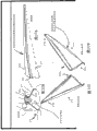
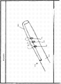
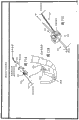
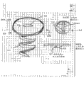
Fig. 1-3 depict various systems and fixation elements or features according to embodiments of the described invention.
Fig. 4-5 depict a multi-purpose tool configuration according to an embodiment of the invention.
Fig. 6-17 depict various tool ("needle") configurations according to embodiments of the invention.
Fig. 18-19 depict a tensioned anchor configuration according to an embodiment of the described invention.
Fig. 20-23 depict a surgical tool and a dilation member according to an embodiment of the described invention.
Fig. 24A-24D depict dilation devices and techniques according to embodiments of the described invention.
25A-25F depict dilation devices and techniques according to embodiments of the described invention.
Fig. 26A, 26B depict dilation devices and techniques according to embodiments of the described invention.
Fig. 27 depicts an expansion device ("expansion member") and technique according to an embodiment of the described invention.
28A, 28B, and 28C depict dilation devices and techniques according to embodiments of the described invention.
29A-29D depict dilation devices and techniques according to embodiments of the described invention.
FIGS. 30A-30E depict dilation devices and techniques according to embodiments of the described invention.
31A-31C depict dilation devices and techniques according to embodiments of the described invention.
Fig. 32A, 32B depict dilation devices and techniques according to embodiments of the described invention.
Fig. 33A-33F depict dilation devices and techniques according to embodiments of the described invention.
Fig. 34A, 34B, 34C, and 34E-34K depict dilation devices and techniques according to embodiments of the described invention.
Fig. 35A-35E depict dilation devices and techniques according to embodiments of the described invention.
36A-36C depict dilation devices and techniques according to embodiments of the described invention.
Fig. 37A-37D depict dilation devices and techniques according to embodiments of the described invention.
Fig. 38A-38B depict dilation devices and techniques according to embodiments of the described invention.
FIGS. 39A, 39B depict dilation devices and techniques according to embodiments of the described invention.
Fig. 40-55 depict various embodiments for securing a mesh implant to a sacrum of a patient according to embodiments of the described invention.
Fig. 58, 59, and 61-64 depict various embodiments for securing a mesh implant to a patient's vagina according to embodiments of the described invention.
Fig. 65-77 depict various embodiments for adjusting the tension of a vaginal apex when secured to the sacrum in a sacral vaginal fixation procedure, according to embodiments of the described invention.
Fig. 78-80 depict various embodiments of transvaginal methods for sacral colpopexy directed to securing a mesh to the anterior ligament of the sacrum according to embodiments of the described invention.
Fig. 81-84 depict various embodiments of methods and devices for securing a mesh to a vaginal wall according to embodiments of the described invention.
Fig. 85A-85D depict a combined levator/prolapse support device according to an embodiment of the described invention.
Fig. 86-87 depict a vaginal tip support device according to an embodiment of the described invention.
Fig. 88A, 88B depict a web tensioning apparatus and method according to embodiments of the described invention.
Fig. 89-90 depict a levator support device according to an embodiment of the described invention.
101-110 depict various embodiments of surgical retractor tools, systems, or components according to embodiments of the described invention.
111-115 depict various surgical dissection tools or systems, including those adapted for use with known or modified introducer needles, according to embodiments of the described invention.
Fig. 116-120 depict various needle tip configurations suitable for use with the present invention (e.g., working channel, light channel, lens, sheath, balloon, cutting blade, etc.) according to embodiments of the described invention.
Fig. 121 depicts an optical needle system for transvaginal delivery of an anchor to the sacrum with a visual viewing device or apparatus according to an embodiment of the described invention.
Fig. 122-129 depict various systems or methods for facilitating sacral tissue fixation according to embodiments of the described invention.
Fig. 130-132 depict various sacral fixation drivers or systems according to embodiments of the described invention.
Fig. 133-137 depict a sacral tissue fixation mesh for use in SCP surgery, according to an embodiment of the described invention.
Fig. 138 depicts an SCP web with anchors.
Fig. 139-140 depict sacral tissue fasteners for a mesh in pelvic surgery (e.g., SCP) according to embodiments of the described invention.
Fig. 141-145 depict a ratchet coil driver for use in a variety of procedures, including SCP procedures, according to embodiments of the described invention.
Fig. 146-147 depict an active tissue retractor for use in transvaginal SCP surgery according to embodiments of the described invention.
Detailed Description
Pelvic floor disorders include cystoceles, rectoceles, vaginal herniations, and uterine and vaginal vault prolapse in both male and female patients. These disorders often result from weakness or damage to the normal pelvic support system. The most common causes include labor, uterine removal, connective tissue defects, long-term heavy physical labor, and post-menopausal atrophy.
Vaginal vault prolapse is the expansion of the vaginal apex, in some cases in a direction toward the outside of the vagina. A posterior vaginal hernia is a vaginal hernia in which the peritoneal sac containing a section of the small intestine extends into the rectovaginal space. Vaginal vault prolapse and posterior vaginal hernia represent challenging forms of pelvic disorders for physicians.
Vaginal vault prolapse is often associated with a rectal prolapse, a vesical prolapse, or a posterior vaginal hernia. It is known to repair vaginal vault prolapse by suturing to the supraspinous ligament or to attach the vaginal vault to the sacrum through the mesh or fascia (fascia). Many patients with vaginal vault prolapse also require surgery to correct symptomatic or latent stress urinary incontinence.
Suspension surgery is a surgical method of deploying a sling to stabilize or support the bladder neck or urethra. They are commonly used to treat incontinence. There are a number of different suspension techniques. The slings used for pubovaginal procedures differ in the type of material and the method of anchoring. In some cases, the sling is placed under the bladder neck through an abdominal incision and/or vaginal incision and secured to an attachment point (e.g., bone) via suspension sutures. Examples of suspension are disclosed in U.S. Pat. Nos. 5,112,344, 5,611,515, 5,842,478, 5,860,425, 5,899,909, 6,039,686, 6,042,534 and 6,110,101.
Sacral vaginal fixation surgery is a procedure used to provide vaginal vault suspension. It may be performed through an abdominal incision, a vaginal incision, or laparoscopically. Complications include mesh infection, mesh erosion, ileus, intestinal infarction, and sacral complex venous bleeding. Typically, such procedures are accompanied by abdominal posterior vaginal hernia repair and rectal uterine pouch occlusion.
Sacral vaginal fixation procedures involve suspending (with the aid of an implant such as a mesh belt) the vaginal discontinuity onto the sacral anatomical region (e.g., the sacrum (bone itself), the adjacent sacral ligament, uterosacral ligament, or the anterior longitudinal ligament at the sacral promontory). Implants such as synthetic meshes can be carefully customized or assembled into specific shapes by a physician. According to some procedures, the surgeon manually cuts the mesh sheet and the suture elements of the mesh to form the particular shape. The literature reports doctors sewing mesh material into a variety of T-shaped articles. See Winters et al, Abdominal Sacral Colpopex and Abdominal Enteropereplaier in the Management of Vaginal Vault Prolapse, Urology 56(Suppl 6A) (2000):55-63, (Abdominal et al, in Urology 56(Suppl 6A) (2000): Abdominal sacrospinous Vaginal fixation Surgery and Abdominal posterior Vaginal hernia repair in Vaginal Vault Prolapse Management published on Urology 6A (2000): 55-63), and Parasso et al, Laparoscalcopic Surgery for Enterocele, Vaginal Apextropalapex Prolapase and Recocele, Int Uynecol J (1999) (Parasso et al, in International gynecological urological journal (1999), Laparoscopic Surgery for posterior Vaginal hernia, Vaginal apex Prolapse, and rectal Prolapse).
In certain SCP procedures, which also involve hysterectomies, the implant can be attached to the posterior vaginal tissue remaining after removal of the uterus and cervix, and also to the anatomy to support the vaginal tissue at or around the sacrum, for example, to the uterosacral ligaments or to the sacrum itself (i.e., a portion of the sacral anatomy).
As used herein, the term "anchor" refers, without limitation, to any structure capable of connecting an implant to tissue of the pelvic region. The tissue may be bone, or soft tissue such as muscle, fascia, ligament, tendon, or the like. The anchor can be any known or future developed structure for attaching an implant to such tissue, or a structure described herein, including but not limited to a clamp, a suture, a soft tissue anchor such as a self-fixating tip (self-fixating tip), a bone anchor, any structure described herein for attaching an implant to soft tissue or bone of the pelvic region, and the like.
Referring generally to fig. 1-19, various embodiments of a tool or system 10 and method are shown for use in a method of treating a pelvic condition, such as a method of performing sacral vaginal fixation ("SCP"). Portions of the system 10 can be constructed of polymeric materials, metals, or other biocompatible or acceptable surgical instrument materials.
Referring generally to fig. 1-3, the SCP apex fixation element is configured to create a structure that closely mimics or replicates the uterosacral ligaments between posterior vaginal tissue (e.g., "vaginal vault," "vaginal apex," or "vaginal amputation") and tissue at the sacral anatomical region. That is, one or more small elastic silicone (or other elastic material) implants (e.g., tubes, strips, bands, etc.) 12 or elastic (solid or hollow) rods can be attached to the vaginal apex (11) and to tissue at the sacral anatomical region (e.g., at or near the sacrum (13)) near the initial fixation point of the uterosacral ligament 9 (fig. 1-2). This configuration using a resilient implant provides at least two distinct benefits. First, the need for critical adjustment of vaginal apex tension is reduced (thereby reducing the dependency on the physician and patient comfort/surgical complexity). Second, by using the resilient material of the resilient implant 12 (which moves and reacts to activity in a manner similar to natural anatomy), the resilient nature of natural anatomical bodies or structures is mimicked.
The resilient material used for the implant 12 can allow the resilient implant to stretch and accommodate a variety of implant techniques and patient activities and movements. The resilient material used in such resilient implant embodiments can take any form or shape having an overall flexible configuration. The elastic material can be a natural or synthetic polymeric material that provides elasticity to the elastic implant that mimics vaginal tissue or uterosacral ligament tissue. For example, a resilient implant having a spring rate of less than 25 lbs/inch (e.g., from 2 lbs/inch to 25 lbs/inch or from 5 lbs/inch to 20 lbs/inch) can be a desirable goal, while other various configurations and levels of flexibility are also contemplated. Examples of suitable elastic materials may include silicone rubber, natural or synthetic rubber, polyolefins, implants containing mechanically resilient springs, and the like.
The elastic implant can have a length from the vaginal vault or other posterior vaginal tissue to tissue at the sacral region (e.g., sacral promontory, fascia, nearby ligaments (sacral ligament, uterosacral ligament, anterior longitudinal ligament), or fascia), and have a desired degree of tension (e.g., due to stretching) on the elastic implant. The elastic implant can be in a relatively flat form or material, such as an elongated elastic mesh, strip, or band, or tubular. The implant may be made of a single resilient material, or the implant may be a composite device made up of multiple components, one or all of which are resilient.
A single specific example of a resilient implant is shown in fig. 2. The elastic implant 12 is an elastic material between the posterior vaginal tissue 11 and the sacral anatomical region (not shown). The anchor 7 can be used to secure the distal end of the resilient implant 12 at the sacral anatomical region. The proximal portion can be attached to the vaginal apex 11 by any useful method.
As one example, fig. 3 illustrates the resilient implant 12 in the form of a resilient polymeric tube having two opposing ends, a first (proximal or anterior) end configured to engage or connect to tissue at or near the vaginal fornix and a second (distal or posterior) end configured to engage or connect to tissue at the sacral anatomical region. The first end can be connected directly or indirectly to vaginal tissue, for example by means of sutures, staples, bioadhesives, anchors, or the like. For example, the first end may be connected via an intermediate structure, such as a barbed anchor (15) having a barbed end configured to fit within the tube 12; the opposite (proximal) end of the barbed anchor (15) can be configured to be secured directly or indirectly to vaginal tissue by any desired anchor or other device (e.g., a clip, self-fixating tip, soft tissue anchor, or anchors such as those described herein, etc.). The second end of the tubular, resilient implant 12 can be connected, directly or indirectly, to tissue of the sacral region, such as by way of sutures, a U-shaped piece, a biological adhesive, or another anchor as described herein or elsewhere, or can be secured to tissue of the sacral region by any other desired structure (e.g., a clip, a self-fixating tip, a soft tissue anchor, a bone anchor, etc.).
The multi-function tool illustrated in fig. 4 and 5 addresses and eliminates the visual observation and fixation challenges typically associated with transvaginal SCP surgery. That is, the multi-function tool 14 is provided and can be used for one or more of the following combined functions: dissection (e.g., by any means such as a blade, hydro dissection, or otherwise), blunt dissection, observation (i.e., "visual observation"), illumination, fluid delivery, irrigation, aspiration, and placement of anchors (bone anchors, soft tissue anchors, e.g., self-fixating tips, sutures, etc.) into the desired target tissue. Fig. 4 is a side perspective view of tool 14, while fig. 5 is an end view at pointed tip 16. Optionally, the tip 16 can be pivoted up to 90 degrees, or alternatively rotated, to navigate around critical anatomy. The surgeon can use tool 14 to accomplish multiple tasks in one pass with one hand and leave the other hand free to complete other parts or steps of the SCP procedure. Tissue damage can be reduced and overall visibility and problem solving capabilities improved.
Fig. 5 is a front (end) view of tool tip 16 depicting an exemplary combination of functions and structures of tool 14, e.g., light source (16 a); a lens (16 b) for a camera or other optical viewing function; a fluid (e.g., liquid) dispensing port, e.g., "flush port" (16 c) for dispensing gas, water, saline, or other liquid or gaseous fluid; a suction port (16 d) for placing a vacuum or suction at the tool tip 16, for example, to remove liquid of gaseous fluid; and an anchor port (16 e) for manipulating and disposing an anchor at or within tissue of the pelvic region, the anchor being in any form such as a suture, clamp, suture needle, self-fixating tip, bone anchor, or any other anchor or fastening or fixation element for securing an implant to tissue as described herein. Each of these features of the tip 16 communicates with the proximal end of the device 14 through a lumen, optical connection, mechanical connection, or electrical connection, if necessary. The proximal end portion (see fig. 4 and 14) can include one or more handles for manipulation by a physician or other user, and can additionally include one or more connectors to permit communication with and operation or manipulation of each structure, port, and functional portion at the tip 16.
In various embodiments, the aspiration port (16 d) and the irrigation port (16 c) can share the same distal tip 16 bore or opening feature.
Light source 16a can be any light source of light source located at the distal end or tip 16 of tool 14. Light source 16a may be connected by fiber optics to a light source (light bulb, Light Emitting Diode (LED), LCD, etc.) at the proximal end, or may include a light bulb or LED or LCD light source at the distal end of tool 14 that is wired to the proximal end. The viewing functionality 16b may be a small electronic camera disposed at the tip 16b in electrical communication with the proximal end, or may include a lens and an optical fiber extending through the shaft of the tool 14 and having one (distal) end at the tip 16 and another (proximal) end at the proximal end of the tool 14, the proximal end in visual communication with the electronic camera. The light source (16 a) and the viewing function (16 b) may or may not share the same port located on the tip 16.
The pivoting of the tip 16 can vary in scope and can exceed 90 degrees, and can also pivot in multiple dimensions, or can alternatively rotate. Additionally, the anchor port (16 e) can be of any configuration or disposed within any portion of the tip 16 or at a location along an adjacent axis.
The tip 16 can also include an anchor port 16e, the anchor port 16e including an engagement structure (e.g., an "anchor interface"), such as a needle tip that can engage with an anchor. The engagement structure corresponds in size and shape to a portion of the anchor and is adapted to engage or grasp a portion of the anchor to permit the anchor interface to retain the anchor, for example, during passage of the tip 16 through the vaginal opening and to the sacral anatomical region, wherein the anchor interface is activatable by a mechanism at the proximal end to securely dispose the anchor within tissue of the pelvic region. This arrangement can be guided by observation of the observation function 16b and illumination of the tissue arrangement with the light source 16 a.
The tool 14, or portions thereof, can be constructed of a variety of known and acceptable materials, including polymers, PEEK, stainless steel, polycarbonate, etc. The overall size of the tool can vary widely. For example, one embodiment can range from 0.200 inches to 1.00 inches in outside diameter. The shaft can have a length sufficient to extend from an external location proximate the vaginal opening into the vagina and through a vaginal incision at the vaginal fornix or discontinuity, and then access the sacrum. Other sizes and dimensions for tool 14 are also contemplated. As noted, the distal portion may optionally include a steering mechanism that enables the distal portion to bend in two or three dimensions by manipulating the steering mechanism located at the proximal portion.
6-17 illustrate various other embodiments of apparatus and methods, including: a needle system 20 comprising a tool having a handle 19; a needle shaft 23 including optional viewing (visual or optical) and illumination (illumination) features for illuminating and viewing the pelvic site for placement of the implant or anchor; and an associated method.
Conventional pelvic implant installation procedures (e.g., SCP procedures) can be performed through an abdominal opening or laparoscopically. Thus, special skills and equipment are required to efficiently complete the procedure. And an abdominal wound was generated. The multifunctional tool is capable of providing minimally invasive surgery without abdominal wounds or potential organ perforation or dissection, with useful distal end functionality (e.g., anchoring functionality, viewing and illumination functionality, steering, aspiration, dissection, anchor delivery, implant delivery, and fluid delivery). By means of the implant delivery tool with viewing and illumination functionality, a clear visual view of the internal tissue is provided for the needle passage of the implant and anchoring, for example, to the sacrum. The physician is able to optically (visually) guide the distal end or shaft of the implant delivery tool (i.e., the "needle") by direct observation, visually identify a potential hazard zone, and guide or steer the needle to the desired target tissue site for placement of the anchor or implant. A faster cognitive curve is provided for the physician to deliver the needle safely by means of the scope and optical observation, and knowledge of the use of the scope in the surgery is applied to and beneficial to the surgery.
An exemplary needle system 20 (with optical and visual functionality) can include a tool 14, the tool 14 including an elongate shaft including one or more separate or integral "shaft" structures, and an anchor interface structure 22d, and the tool 14 can be constructed of a flexible or rigid biocompatible material (e.g., a rigid or flexible polymer, stainless steel (high strength and high modulus of elasticity), etc.). The shaft or shaft assembly can have a small diameter, but is sufficiently rigid to allow useful and safe passage and guidance.
Referring to fig. 6, 7, and 8, the one or more anchors 22 can be configured to not only secure to tissue at the sacral anatomical region, but also to enable light to enter into or exit from viewing or illuminating features of the insertion tool. For example, the anchor 22 can include an aperture, lens, or opening for the passage of light, and can be constructed of a transparent or translucent biocompatible material suitable for implantation, and also allows visual illumination and observation for guidance within the patient. For example, various anchors and similar attachment devices, tools, systems and methods as disclosed in U.S. Pat. Nos. 7,500,945, 7,407,480, 7,351,197, 7,347,812, 7,303,525, 7,025,063, 6,691,711, 6,648,921 and 6,612,977, International patent publication Nos. WO 2008/057261 and WO2007/097994, and U.S. patent publication Nos. 2002/151762 and 2002/147382 can be employed by the present invention. Accordingly, the entire disclosure of the above disclosure is fully incorporated herein by reference.
In such embodiments, the system 20 can include an elongate shaft with a fiber optic light source and a multi-function tool of imaging fiber bundles (e.g., as shown in fig. 9 and 13-17) integrated therein. The system 20 can include features to facilitate tissue anchoring by delivery of one or more anchors 22 (e.g., as illustrated in fig. 6, 7, and 8). Fig. 6 illustrates a soft tissue anchor (e.g., "self-fixating tip") that includes an internal channel (or "needle hub" 22 a) that extends from a proximal end (22 b) (connected to suture 23) to a distal end (22 c). The channel (or "needle interface") 22a can be adapted to engage the anchor interface surface of the shaft or the distal end of the anchor engaging portion, optionally allowing light to be transmitted between the distal ends of the anchor interface to allow for illumination and optical viewing of tissue and the surgical site by way of the illumination and viewing functionality. The extension 26 can allow for secure placement of the anchor 22 at the tissue, preventing movement in a posterior direction after pushing the anchor 22 into the tissue. The anchor 22 can optionally include a light directing feature (25) at its tip to direct light from the end of the fiber optic cable through the anchor 22 onto tissue being visually observed.
The tool 14 is preferably capable of being discarded after a single use but is capable of being adapted to work with reusable imaging (i.e., "viewing") and illumination fiber bundles, each of which can be inserted into the shaft prior to surgery. Both the illumination fiber bundle and the imaging fiber bundle are reusable and are constructed as a single element. Alternatively, the illumination fiber bundle can be independent of the imaging fiber bundle. Preferably, the illumination fiber bundle can be disposable and attached to or incorporated into the shaft. The imaging fiber bundle can be self-contained and reusable, meaning that the imaging fiber bundle will be protected from bodily fluids, for example by a lens at the distal end of the shaft to contain the imaging fiber bundle within the shaft.
Referring to fig. 9, the tool 14 (of system 20) can include illumination and viewing functionality including one or more of the following: a light source, a lens, a working cavity, optical fibers (e.g., illumination beam 21b and imaging ("viewing") beam 21 a) extending between a proximal end (including a handle, toward the operator) and a distal end (toward the patient), and a camera or other video device (not shown) located at or connected to the proximal end. As illustrated, the imaging fiber bundle 21b can include a plurality of fiber optic cables arranged or useful as desired, with one end (distal end) of the fiber optic cables located at the distal end of the tool 14 and a second end (proximal end) located at the proximal end of the tool 14. The imaging fiber bundle 21a can allow observation (visual inspection) of the illuminated tissue through the illumination function. In one arrangement, there is provided an imaging bundle 21a and an illumination bundle 21b, wherein the imaging bundle 21a is centrally located and the illumination bundle 21b circumferentially surrounds the imaging bundle 21 a. In a different arrangement, the imaging beam 21a can be located next to the illumination beam 21b or otherwise provided independently of the illumination beam 21 b. Thus, the light source and illumination beam (21 b) can be detached or separated from the imaging beam 21a as a whole to allow visual inspection of tissue structures without glare or illumination leakage into the imaging fiber bundle 21 a. Optionally, the imaging bundle 21a can be located inside the shaft, within a cavity (not shown), and with a sealed lens at the distal end to prevent the imaging bundle 21a from contacting the patient's tissue or bodily fluids during surgery and to allow for reuse of the imaging bundle 21 a.
Still referring to fig. 9, located at the distal end of the shaft is an anchor interface feature 22d for engagement with a channel or "needle interface" feature 22a of an anchor 22 (not shown). The anchor interface feature 22d can be in communication with one or both of the imaging ("viewing") beam 21a and the illumination beam 21b to enable light and images to be transmitted through the tip 22 between tissue adjacent the tip 22 and each of the imaging beam 21a and the illumination beam 21 b. Alternatively, the shaft (i.e., the "needle") may include an illumination beam 21b and an imaging beam 21a along the needle (through the lumen along the length of the needle), and an aperture or opening at the side or end of the needle can allow illumination and viewing. Viewing may be through the distal lens or opening. Illumination may be through a side or distal end hole, through an aperture in the anchor 22, or by means of a transparent or translucent anchor 22.
The anchor interface feature 22d can optionally be located at a distal end of a separate shaft structure disposed within a shaft (23) of the tool 14 (e.g., disposed in a longitudinal cavity or channel). This allows the independent shaft structure including anchor interface feature 22b to be movable within shaft 23 and to be extended and retracted distally from the distal end of shaft 23 (by a mechanism provided at the proximal end of tool 14). Optionally, the anchor interface 22d may include detents or other mechanisms to permit selective engagement and disengagement of the anchor by distal extension and retraction for deployment in tissue.
An optional sheath 24 can be included along the entire length or distal length of the shaft 23 to cover and protect the tissue anchor (22) until deployment from the shaft 23, as shown in fig. 10-12. The sheath (24) can be a simple guard covering the shaft (23) to hold and protect the anchor and allow fluid irrigation (by means of fluid delivery and optional suction functions) to the tissue site for water dissection, or irrigation of the optical (viewing) lens or irrigation of the anchor site to allow better visual observation in the presence of blood, fat or other tissue or fluid. Alternatively or additionally, the sheath 24 may also include illumination or imaging (viewing) functionality by including one or more fiber optic cables for illumination or imaging (viewing). For example, the sheath 24 may include a fiber optic cavity or other fiber receiving feature to hold the fiber optic cable and direct light onto the anchor or directly onto the tissue, or to allow imaging or viewing of the tissue.
Also optionally or alternatively, the sheath 24 can include other features, such as an irrigation port that can be used to irrigate the surgical site to allow water dissection and better visual observation by irrigating the implant site and the lens for imaging the fiber optic bundle. Additionally, the jacket 24 can assume a variety of configurations with channels, ports, integrated fiber optic cables, tubes, and the like. See fig. 10, 11 and 12.
In fig. 10, the sheath 24 can be a simple polymeric rigid, flexible or semi-rigid tube with two open ends that fits onto the shaft of the tool 14. Such a sheath is described and illustrated in applicant's co-pending U.S. publication No.2010/0274074 entitled pelvic floor treatment and related tools and implants, the entire contents of which are incorporated herein by reference.
Fig. 11 shows a sheath 24 similar to the sheath 24 of fig. 10, but additionally comprising a cavity 24a for an illumination fiber (optionally an illumination fiber 24 a). As shown, the cavity or illumination fiber 24a may be external to the shaft 24 (left view) or integral to the side wall of the shaft 24 (right view).
Fig. 12 shows a sheath 24 similar to the sheath 24 of fig. 10, but additionally comprising a cavity 24a for the illumination fiber (optionally illumination fiber 24 a) and a cavity 24b for the imaging fiber (optionally imaging fiber 24 b). As shown, each cavity or illumination fiber may be external to the shaft 24 (left view) or integral to a side wall of the shaft 24 (right view).
The system 20 shown in fig. 13-14 can include an imaging system 26, the imaging system 26 having a light source, a camera, a display, a computer to process and store data, and imaging and illumination beams (21 a and 21 b) to interface with the needle system 20. Thus, light can be emitted from the anchor 22 (not shown) toward a target tissue (e.g., pelvic ligament, muscle, fascia, sacral tuberosity ligament, location at the sacral anatomical region, etc.). The distal end of the shaft as illustrated includes: an optional inflow or aspiration port, an illumination port for illuminating tissue, an imaging port for viewing tissue, and an anchor interface engageable with an anchor (e.g., a channel from a fixation tip). The anchor can be translucent or include holes or apertures to enable light to be transmitted from the illumination port (e.g., at the shaft or needle) to the tissue. The anchor, shaft (needle), or another location at the distal end of the tool 14 may include a lens in communication with an imaging port to permit viewing of tissue at or near the anchor.
As shown in fig. 15-17, a custom-made or adapted sheath 24 can be provided with a standardized incontinence or prolapse repair needle system to include the necessary lumens (as part of the sheath 24) to provide versatility as described (e.g., a central imaging fiber lumen, and an illumination fiber lumen). In this embodiment, the tool 14 can include a shaft, which can be a standardized solid metal rigid needle 23 with a custom sheath containing three lumens: a central cavity for receiving the needle; an imaging fiber cavity housing a fiber optic cable for imaging (viewing) a tissue site; and an illumination fiber optic cavity housing a fiber optic cable for illuminating the tissue site. The sheath 24 may be flexible (e.g., made of a polyolefin such as polyethylene or polypropylene) and capable of conforming to the shape of the needle. The needle can be malleable or rigid, optionally bent into a desired shape by the surgeon during surgery. The cost and ease of using and manufacturing extruded multi-lumen sheaths, such as polyethylene, can be improved when compared to other more complex shaft configurations for multi-function tools. Fiber optic cables for illumination or for viewing may be disposed at the outer surface of the polymer jacket 24, at the inner surface of the polymer jacket 24, or within the lumen or integral with the sidewalls along the length of the polymer jacket 24 (bending the multi-lumen jacket during manufacture may shrink the inner lumen). The lens can be disposed at the end of one or two or more fiber optic cables to enable the optical fiber (e.g., imaging fiber) to be reused by sliding the optical fiber into and out of the cavity of the jacket. Optionally, one or both of the imaging fiber and the illumination (illumination) fiber can be attached to the sheath and can be discarded along with the sheath. The needle tip extending through the (main) interior cavity of the sheath can comprise a distal end for engagement with an anchor (e.g., a self-fixating tip), or can comprise an aperture extending to a proximal end for a suture or irrigation or aspiration channel or port.
The embodiments of fig. 18-19 can include a tensioning or tensionable anchor 30 for use in pelvic therapies (e.g., SCP surgery). Anchors 30 can take on various designs and configurations as are known, disclosed, or incorporated herein. In particular, a pulley system 32 including an eyelet 34 (e.g., on the anchor 30) and a suture 36 can be used to provide tensioning or adjustment of the anchor 30 relative to an implant attached to the suture 36 when the anchor 30 is attached to the sacrum or another portion of the sacral portion structure. Thus, the ends of the suture 36 can be tied or attached to the vaginal apex by the implant, while the remainder of the suture passes through the eyelet 34 of the anchor 30 and proceeds out of the body via the vagina. This allows dynamic adjustment of the tension and support of the vaginal apex. A variety of known materials can be used to construct the various portions of this embodiment, including polycarbonate, polypropylene, polyethylene, suture material, and the like.
Referring generally to fig. 20-24, various embodiments of a surgical tool 50 having an elongate shaft and a tube 52 are illustrated. The tool 50, including a shaft, is generally configured for use during surgery to facilitate guidance and passage of the canal 52 to a surgical site or anatomical structure (e.g., a sacral anatomical region). Tool 50 allows tube 52 to be placed in the patient through an incision to enable tube 52 to provide access to an internal surgical site, for example for placement of a surgical implant. The tube 52 can be used to advance a surgical object such as a tool, suture, implant, or component thereof, or other object (e.g., a sharp object) to an internal surgical site (through the tube 52) without having to make multiple attempts from an incision to an anatomical target area. Optionally, the surgical tool 50, the tube 52, or both can include functional portions for illuminating or viewing the surgical site for dissection, irrigation, placement of anchors, etc., as described herein for the multi-functional tool. For example, if the components of the surgical tool 50, the tube 52, or both are plastic or polymeric light conducting material, light can be transmitted through the material from the proximal end to the distal end at the surgical site.
The tool 50 includes a handle 58 on the proximal end portion, an elongate shaft extending from the handle to the distal end portion, and an elongate tube 52 associated with the elongate shaft. In general, the "tube" can be a hollow elongate structure, such as a rigid or flexible sleeve, retractor, expansion member, or similar structure that includes an open channel hollow interior and allows access between the patient's exterior and the pelvic region when disposed within the patient during surgery.
In certain embodiments, the tube 52 can be used to access male or female pelvic anatomy, particularly transvaginal access to female pelvic anatomy, to access tissue of the posterior pelvic region, for example, to perform SCP surgery. Tube 52 can have a length that allows for such access when the tube is transvaginally deployed, such as a length that allows for a distal portion of the tube to access pelvic tissue when a proximal portion of the tube is extended through the vaginal opening to a location external to the patient. The proximal end of the tube maintains the exterior of the patient during use to enable a physician or other user to access and manipulate the proximal end and through the tube to access the surgical site at the distal end. Exemplary lengths between the proximal and distal portions may range between 13 centimeters to 18 centimeters, particularly for use in female patients to transvaginally access a location of the posterior pelvic region (e.g., a sacral anatomical region).
The diameters of the elongate shaft and tube portion of the tool can be used to allow insertion and deployment of the tool with reduced trauma. Optionally, as described elsewhere herein, the diameter of the tube can be varied (e.g., by expanding the tube after it is disposed within the patient) to allow for increased and expanded access to tissue located at the surgical site.
Optionally, the tool can include one or more functional features (e.g., for surgical tool 14 as previously described herein) at the distal end of the tool, or at the distal end of the tube or at the distal end of the shaft, including functions that enable tool 50 or tube 52 to be used to perform such functions as dissection (mechanical dissection with sharp blades, or water dissection), blunt dissection, visualization (visual observation) of the surgical site, illuminating the surgical site, fluid delivery at the surgical site, irrigation at the surgical site, suction at the surgical site, steering of the distal end of the shaft or tube, or both, and placement of anchors (bone anchors, soft tissue anchors such as self-fixating tips, sutures, etc.) within desired target tissue at the surgical site.
The various systems, instruments and methods detailed herein are contemplated for use with a number of known implants and repair systems (e.g., for males and females), features and methods, including those disclosed in U.S. patent nos. 7,500,945, 7,407,480, 7,351,197, 7,347,812, 7,303,525, 7,025,063, 6,691,711, 6,648,921 and 6,612,977, international patent publication nos. wo 2008/057261, wo2007/097994, wo2007/149348, and 2002/151762, 2010 0174134, 2010 0298630 and 2002/147382. Accordingly, the entire disclosure of the above disclosure is incorporated herein by reference.
Fig. 20 shows a single example of a tool deployed for accessing a "tube" 52 of a surgical site at a pelvic region. The tool 50 in fig. 20 can include a leading distal end 54, a shaft 56 (e.g., inside the tube 52), a tube 52 (e.g., disposed at the exterior of the shaft 56), and a handle 58. Additionally, a spring, spring activated, mechanically activated, or other type of cutting mechanism 60 can be included in any location along the tool 50 to facilitate cutting (for dissection) and/or activating the distal end 54 to create a small incision in the patient's anatomy. The tube 52 can be separated from the shaft 56 as the cutting and guiding tool 50 is passed through a tissue path (e.g., transvaginally in a female patient) to a target area of tissue. The handle 58 and shaft 56 can be removed from the patient while leaving the tube 52 (i.e., can remain in place during the surgical deployment procedure) to provide a defined path or channel to the surgical area (site) for accessing the surgical area (site). In a particular method of SCP treatment of transvaginal female anatomy, the tube 52 is arranged with the proximal end portion extending out of the patient's vaginal orifice, the tube extending through the vagina and vaginal incision, and the distal end portion disposed at a posterior portion of the patient's pelvic region, e.g., proximate the sacral anatomical region.
As shown in fig. 21, 22, and 23, the tool 50, including the tube 52, can assume a variety of different shapes and size configurations and can be advanced anatomically through the vagina and introitus and into the posterior portion of the pelvic region (near the sacrum). The tool 50 and tube 52 can be used to provide access to a variety of other anatomical structures or sites without departing from the spirit and scope of the present invention.
The tool 50 and tube 52, or portions or components thereof, can be constructed of any known or compatible material, including polymers or metals. The tool 50 and tube 52, their various components, structures, features, materials, and methods may have various suitable configurations as shown and described in the previously incorporated references.
Alternative embodiments of devices (e.g., "dilation member," "retractor," or "tube") used in a similar manner to tube 54 are also contemplated for accessing internal tissue of the pelvic region through an incision in a male or female patient, e.g., a tissue retractor for transvaginally accessing the posterior region of the female pelvic anatomy. Any of these tubes 54 and others can be used in accordance with one or more of the methods described herein for deploying an implant for supporting pelvic tissue, such as SCP surgery using any one or more of the implants, insertion tools, multi-functional tools, anchors, etc., described herein.
Various such embodiments of "expansion members" are described below and may have the following overall structural and operational features: it enables one or more flexible, rigid, or semi-rigid distal retraction structures to be introduced through an incision (e.g., a vaginal incision) in a closed, compressed, or reduced size or diameter state, then moved, assembled, or expanded to enlarge the cross-sectional size or associated space or opening to push tissue laterally, thereby creating space in the pelvic region and creating access to the pelvic region to access the desired pelvic anatomy. Preferred dimensions of the device can include a range from 1cm to 5 cm (e.g., from 2 cm to 4 cm) when the distal retraction structure is in its reduced size configuration (these are referred to herein as the diameter range d)1) For example, a width or diameter associated with an opening along the length of the device. When the distal retracting structures are open, uncompressed, expanded, or assembled, etc., preferred dimensions associated with these structures (e.g., width or diameter associated with the opening along the length of the device) can range from 2 centimeters to 10 centimeters (e.g., from 3 centimeters to 7 centimeters) (these are referred to herein as diameter ranges d)2). It is also common that these structures (tubes, retractors, etc.) can include a desired length dimension (from proximal to distal end) that can be selected to work with a particular anatomy (male or female) and surgery (anterior repair, posterior repair, etc.). The length of the particular structure (tube, retractor, etc.) used in the transvaginal approach to treating pelvic conditions (e.g., SCP surgery) can be sufficient to enable the distal portion to reach the sacral anatomy while the proximal portion remains at or outside the introitus. The relevant dimension is the "working depth" of such a device, which is the distance between the distal ends of the device when it is installedThe distance between the portion and the vaginal opening, and it can be any useful or desirable size, such as from 13 cm to 18 cm. The distance that the device extends proximally out of the vaginal opening away from the patient is preferably minimized. Still referring to the use of these devices in transvaginal treatment procedures, another relevant dimension is the "working space" dimension, which is the transverse dimension of the opening at the proximal end of the device, such as a diameter, which preferably may range from 3 cm to 8 cm; in a transvaginal approach, this is the approximate diameter of the introitus that is held open by the proximal portion of the device.
24A-24D illustrate a pressurized tube expansion member and technique according to an embodiment of the present invention. These figures illustrate specific embodiments of a retractor type of expandable "tube" (100) and a separate inserter device (retractor) in the form of a shaft (104), which shaft (104) can be disposed within the tube 100 to assist in the placement of the tube within a male or female patient. The shaft-tube configuration can be used to allow the tube to expand within a patient, creating a passageway through the tube to allow access to the patient's internal anatomy, such as the pelvic region. The pressurized tube concept uses pressure generated by a syringe or other device to expand a small flexible tube (similar to a catheter deployment system, but larger). Due to the flexibility of the elastic tube, the outer tube can be inserted through a rigid member (e.g., a tube, rod, introducer device, or other more rigid inserter device that can open the vaginal cavity) and then expanded before or after the rigid member has been removed. After expansion of the tube, another rigid replacement tube can be disposed over the expanded tube to provide an open working space to the pelvic anatomy (e.g., sacrum), and the expanded tube can be removed. The tube can be designed to provide a working depth and working space as described herein.
Referring to FIG. 24A, expandable tubular 100 includes a distal end 102 and a proximal end 106. Expandable tubular 100 further includes an opening at each of the proximal and distal ends, and a continuous channel or opening extending between the proximal and distal ends. The structure of the tube (i.e. the side wall of the tube) comprising a single space or a plurality of spacesA space forming an inner space of one or more balloons or balloons, adapted such that the inner space (not shown) capable of being filled with fluid causes the tube 100 to expand in a manner that increases the diameter of the tube and increases the size of the openings at the distal and proximal ends. Fig. 24A and 24B show the tube in a relaxed, contracted (reduced diameter) state. The diameter of the tube in this contracted state can be the diameter at which the contracted tube is effectively (e.g., with reduced patient trauma) disposed within the patient, typically by means of the shaft 104, as desired. Preferred diameters can range from 1cm to 5 cm, such as from 2 cm to 4 cm (these are referred to herein as the diameter range d)1). Which is approximately equal to the outer diameter of the shaft 104.
Still referring to fig. 24A, the insertion tool 104 can be used to place the tube 100 within a patient for surgery. The tool 104 can include an elongated flexible, rigid, semi-rigid, or malleable shaft, needle, or rod 104 ("shaft" 104) to support the tube 100. In use, by disposing the tube 100 at the outer surface of the shaft 104, the distal end portion 102 can be inserted into a patient (e.g., transvaginally into a female patient) while the tube 100 is in a collapsed, non-expanded condition to cause the distal end portion 102 to be disposed at a desired tissue location (e.g., at or near a sacral anatomical region). Before or after removing the shaft 104, a pressurized fluid (e.g., a liquid or gas such as water, saline, or air) can be introduced into the interior space of the tube 100 to fill and pressurize the space. In the collapsed state, the tube 100 may optionally include a pleat or fold that will become wrinkle-free or fold-free when the tube 100 is expanded to the expanded state. Alternatively, the tube 100 may be an elastic material that is expanded to transition between a contracted state and an expanded state.
Fluid may be introduced into the interior space by any useful method and device, such as by way of a syringe 108 located at a port 110 of the proximal portion 106. Introduction of the fluid will expand the tube to the expanded state as shown in fig. 24C and 24D, with an expanded diameter that can be any desired diameter, for example ranging from 2 cm to 10 cm ((s))E.g., from 3 cm to 7 cm) (these are referred to herein as the diameter range d)2) Of (c) is measured.
The expanded tube 100 has strength and lateral and longitudinal rigidity sufficient to enable the tube 100 to create an opening in tissue in the pelvic region by dilating the tissue (e.g., when transvaginally deployed). Optional mechanical reinforcement may be included along the length or circumference of the tube 100, if desired. In use in transvaginal surgery such as SCP (optionally in conjunction with tools, multi-functional tools, implants, adjustable implants, anchors, or other devices or methods described herein), the shaft 104 is used to insert the tube 100 into the vagina and to position the distal end 102 near the sacrum. The patient's tissue will contract around the tube 100. The tube 100 is then pressurized to force the tissue to expand and open around the increased diameter tube 100 to create access to the posterior portion of the pelvic region, e.g., to gain access to the sacral anatomy. Optionally, after the tube 100 is expanded within the patient, another tube, for example, of greater mechanical strength (e.g., a tube or retractor or expansion member as described herein and providing a working depth and working space as described) can be disposed over the expanded tube within the patient to provide open access to pelvic anatomy (e.g., sacral anatomy), and the expanded tube 100 can be removed.
Many other embodiments of tubes (e.g., tube 100) can be useful and used as described, but with different structures and features of the tube. Examples of these other embodiments are described herein and illustrated, for example, in fig. 25-39 and 101-110. Any of these illustrated and described devices (interchangeably referred to as "expansion members," "tubes," or "retractors") can be used or useful by methods that insert the device within a surgical incision (e.g., a transvaginal incision) and expand the tissue to approximate the desired anatomy. To perform SCP or other transvaginal procedures, the tube or retractor can be transvaginally deployed, for example, in an unexpanded, contracted state. The structure can then be expanded (optionally by assembly) while in place transvaginally to create access to a desired anatomical structure (e.g., a posterior portion of the pelvic region), such as to gain access to a sacral anatomical region. A surgeon can perform a procedure with the aid of the access, which provides a working space for pelvic anatomy (e.g., sacrum). The method can also optionally involve a tool, multi-functional tool, implant, adjustable implant, anchor, or other device or method described herein. Optional features and structures (e.g., optical fibers) that allow for viewing or illumination at the distal end can be incorporated into any of these types of devices. For example, if the structural components of the device are made of a plastic or polymeric light conducting material, light can be transmitted through the material from the proximal end to the distal end at the surgical site. Optionally, a fiber optic cable can be incorporated into a length of the device (extending from the proximal end to the distal end or toward the distal end) to enable light to be transmitted from the proximal end to the distal end, or to enable images to be transmitted from the distal end to the proximal end. Light can optionally be generated and emitted from the distal portion.
Referring to fig. 25A-25F, a self-expanding nitinol stent 120, deployment tube (e.g., catheter) 122, and manually-operated retractor device 124, and technique, according to an embodiment of the present invention, are shown. Self-expanding (e.g., nitinol) stents can use the self-expanding (expandable) strength of nitinol or similar metallic or polymeric materials. The stent 120 is biased to an open (uncontracted, or "deployed" state), with the stent 120 having a reduced length and an increased diameter (d)2) And can be contracted and extended to have a greater length and a reduced diameter (d)1) Is deployed. Uncontracted (deployed) stents can be contracted (closed) and elongated by applying lateral pressure to the stent surface, such as at the ends or locations along the length of the stent. Stents for use with the methods described herein can be set (biased) to expand and self-expand when a deployment tube (122) is removed from the outer diameter and outer surface. The bracket can be designed to provide a working depth and working space as described herein.
In useAt this time, a collapsed stent 120 disposed within a deployment tube 122 (see fig. 25A) can be, for example, transvaginally disposed within a patient's body with a distal end disposed proximate a desired anatomical region (e.g., sacral anatomical region). The deployment tube 122 can be removed and the stent 120 expanded to an expanded diameter (e.g., d) within the patient2) Thereby creating an opening within the interior of the expanded stent 120 between the proximal and distal ends of the stent 120 (e.g., between the vaginal opening and the sacral anatomical region). The lengthwise opening allows access for surgery. The stent 120 has a strength and lateral and longitudinal rigidity that enables the tube to expand to create an opening in tissue of the pelvic region by expanding the tissue. Surgery (e.g., SCP) can be performed by accessing the pelvic anatomy through the space (channel or opening) created by the expanded stent. After the procedure, the stent can be removed, optionally collapsed and then removed.
Alternatively, the stent 120 may be contracted by reinserting the stent at the proximal end (outside the patient) into the deployment tube 122. Deployment tube 122 can be disposed at the proximal end and advanced distally along the length of stent 120, causing stent 120 to contract. Optionally, the stent 120 can include a tether (e.g., suture, etc.) 124, and the tether 124 can be attached to the stent 120, for example, at the proximal end. Optionally, to reinsert stent 120 within deployment tube 122, tether 124 can be pulled in a proximal direction (away from the patient) while deployment tube 122 is advanced in a distal direction (toward the patient). This combination of steps can effectively allow the stent 120 to retract/compress back into the original deployment tube 122.
Another alternative means for manually expanding and contracting the housing 120 can be a "manually-operated retractor" 128 that fits around the end of the housing 120 to apply pressure to the end of the housing. The manually operated retractor can include: jaws that contact the ends of the housing 120, handles that control the size of the jaws, and a quick connector that can lock the manually operated retractor in any position. See fig. 25E and 25F.
FIGS. 26A and 26B illustrate a method according toExpandable stents 140 and techniques of embodiments of the present invention. Expandable stent 140 is similar in size and strength to stent 120 of fig. 25A-25F. Optionally, the stent 140 includes shape memory features. For example, the scaffold 140 can be stable (unbiased) and can exist in a non-deployed (contracted) state prior to use, such as diameter d1To (3). A deployment device, such as an expandable catheter, deployment tube, or similar construct (not shown), can be disposed within the interior of the stent 140 and used to place the stent 140 at a desired anatomical location, e.g., transvaginally. The deployment device can then be expanded within the stent 140, causing the stent 140 to expand to an expanded state within the patient. The deployment device can then be compressed and removed to leave the stent in the desired expanded state. The alternative expansion mode can be a tapered object or introducer that is advanced from the proximal end to the distal end after the stent 140 is desirably disposed within the patient. The shape memory feature enables the stent 140 to adapt to and maintain an expanded diameter (e.g., d) within a patient's body2) Creating a space within the interior of the dilating stent 140, for example, between the vaginal orifice and the sacral anatomical region. This space allows access for surgery. The stent 140 has strength, transverse and longitudinal rigidity, and shape memory characteristics that permit expansion within the patient's body to create an opening in tissue in the sacral region by expanding the tissue and maintaining the tissue in an expanded condition.
Referring to FIG. 27, malleable retraction system devices and techniques are shown in accordance with embodiments of the present invention. The malleable retraction system can be adapted to the frame of a variety of different existing retraction system devices, such as those used in vaginal procedures (e.g., a stand-alone star retractor system). The new device will involve one or more malleable retractor arms 152, the arms 152 being attached directly to the retractor frame 150 and extending into a surgical incision (e.g., a vaginal incision) to create access to the desired anatomy (e.g., anchor location). Retractor systems with malleable retractor arms can be designed to provide a diameter d as described herein2Work depth and work space.
Still referring to fig. 27, during use, the frame 150 can be disposed to permit access to the vaginal opening and disposed outside of the patient. One or more retractor arms 152 can be connected to the frame 150 and introduced through the vaginal opening, optionally through a guide incision, and then moved into a position that allows access to the posterior pelvic anatomical region (e.g., sacral anatomical region). Each arm can be malleable, and optionally, additionally, or alternatively, flexible and lockable into a rigid position. In use in a transvaginal procedure (e.g., SCP), the retractor arms 152 are inserted into the vagina and the distal end is disposed at a posterior location (e.g., near the sacrum). The patient's tissue can be moved and expanded to create access to the posterior portion of the pelvic region, such as to gain access to the sacral anatomical region. Once the retractor arms 152 have been arranged as desired to approximate the anatomy, the malleable or flexible arms can be rigidly locked in place. The surgeon can perform the desired procedure after which the frame 150 and retractor arms 152 are removed.
Referring to fig. 28A, 28B and 28C, a forced expansion blind (blind) device and technique is shown, according to an embodiment of the present invention. The force expandable blind includes a coiled, flexible or malleable expandable tubular 158 and a mechanical means of expanding the coiled material from the collapsed expandable tubular 158 into the expandable tubular that provides access to the surgical site. Still referring to fig. 28A, 28B and 28C, expandable tubular 158 is removably engaged at the end of syringe 162, syringe 162 having plunger 160 movable within the barrel of syringe 162. The end of the plunger 160 is shaped to mechanically deform the coiled material (tube 158, in the contracted state as shown in fig. 28A) into a new expanded (uncontracted) size and shape by extending the tip of the plunger out of the syringe barrel and distally into the coil. Once completed, the tip of the plunger is withdrawn within the hollow rigid tube, leaving the dilation tube 158 (see fig. 28C) in place for the procedure. Expandable tubular 158 can be designed to provide a working depth and working space as described herein.
When in use, the device is arranged on the injectorA shrink tube 158 (fig. 28B) at the end of 162 can be, for example, transvaginally disposed within the patient with the distal end disposed proximate a desired anatomical region (e.g., sacral anatomical region). The plunger 160 can be moved out of the distal end of the syringe barrel and into the shrink tube 158 (diameter d)1) To an expanded diameter (e.g., d) that causes the collapsible tube 158 to expand into the patient2) And a space within the interior of the dilation tube 158 is created, for example, between the vaginal orifice and the sacral anatomical region. This space allows access for surgery. The dilation tube 158 (see fig. 28C) has a strength and transverse and longitudinal rigidity that allows the tube to expand to create an opening in tissue of the pelvic region by dilating the tissue.
Referring to fig. 29A-29D, retractor systems and techniques according to embodiments of the present invention are shown. The present system uses a parallel system that moves one retractor arm (168) relative to the other along a rack (which may be a ratchet), or otherwise allows for selective movement and fixed positional relationships between the arms 168. By expanding and manipulating the system 166, the retractor arms are moved closer together or farther apart, allowing the retractor arms to create space in the pelvic region for access to the desired anatomy. The retractor system can be designed to provide a working depth and working space as described herein.
With reference to fig. 29A, 29B, 29C, and 29D, retraction devices and techniques according to embodiments of the present invention are illustrated. The retractor system 170 can include a frame made of a retractor member 172 and a rack member 174. Retractor member 172 is selectively movable along rack member 174 and is engageable with rack member 174 to prevent movement after placement as desired to retract tissue using retractor arm 168. The retractor member includes a proximal end that rides on or otherwise engages rack member 174, and additionally includes a retractor arm 176. Optionally and as illustrated, the retractor arms 168 are curved away from each other at their distal ends to improve separation of tissue by means of the retractor arms 168.
During use, the frame comprising the rack member 174 and retractor member 172 is disposed onto the frame at the vaginal opening and allows access to the vaginal opening. One or more opposing retractor arms 168 connected to opposing retractor members 150 can be introduced into the vagina through the introitus and vaginal incision, and then moved such that a distal end of each retractor arm is disposed adjacent to a desired region of the posterior pelvic anatomy (e.g., the sacral anatomy). Each arm can be rigid or malleable, and optionally, additionally or alternatively, flexible and can be locked in place. In use in a transvaginal procedure (e.g., SCP), the retractor arms 168 are inserted into the vagina (180) and the distal end is disposed at a posterior location (e.g., near the sacrum). See fig. 29D. Movement of the retractor member 172 along the length of the opposing rack member 174 enables the distal end of the retractor arm 168 to move pelvic tissue of the patient and expand the pelvic tissue to create access to the posterior of the pelvic region, e.g., to the sacral anatomy. Once the arm 168 has been positioned as desired proximate to the anatomy, the retractor arm 172 can be locked in place along the length of the rack member 174. The surgeon can perform the desired procedure, after which the retractor system 170 can be removed.
30A-30E, an expansion member 190 and technique including a plurality of folded side members 192 according to an embodiment of the present invention is illustrated. Each expansion member 190 includes a side member 192, the side member 192 being foldable into a reduced cross-sectional profile (size of opening) in a folded configuration (as shown in fig. 30A and 30C). The folded side members can be unfolded and optionally assembled to open (expand) the expansion member to an unfolded (expanded, open) configuration as shown in fig. 30B and 30D. The two variations shown in the figures generate a multi-sided (unfolded) shape from a single two-dimensional (folded) part. The two-dimensional folding part includes several small members (side members) that can be unfolded and assembled to create a three-dimensional shape with an opening between the distal and proximal end portions that provides access (in the form of a tube, channel, or other opening) for accessing and visually viewing the surgical site). The cross-sectional dimension of the expansion member in the deployed configuration can include dimension d as described herein2Work depth and work space. As shown in fig. 30E, any useful form of locking, closing, assembly or securing mechanism can be included as desired to maintain the strength and rigidity of the deployed (open) dilation member 190. The expansion member 190 as illustrated includes 3 and 4 folded side members 192, and may include more side members 192, such as 5,6, 7,8 or more as desired, to create different fold geometries and folded and unfolded sizes and shapes.
The dilation member 190 can be used as generally described elsewhere herein to perform pelvic procedures (e.g., SCP or other pelvic procedures); such as by transvaginally inserting in a folded configuration, opening the expansion member 190 to a deployed configuration to create access into a posterior pelvic site, performing the procedure, and subsequently removing the expansion member 190 (optionally by folding prior to removal). The method can optionally be performed in conjunction with any one or more of the tools, multi-functional tools, implants, adjustable implants, anchors, or other devices or methods described herein.
Referring to FIG. 31, illustrated are embodiments and techniques of an expansion member including a rotating stop/wedge side member according to embodiments of the present invention. The rotating stop/wedge side member device involves an expansion mechanism similar to a camera stop that manipulates (rotates) circumferentially assembling a plurality of triangular side members for independent rotation to expand or contract an object (e.g., an operation opening). In this example embodiment, there are 4 small triangular objects (side members) that are independently rotated one after the other as desired to open and expand the surgical opening or incision to a desired size.
Still referring to FIG. 31, there is shown an expansion member 200 and technique including a plurality (four as shown) of rotational side members 202 according to an embodiment of the present invention. The expansion member 200 includes triangular (cross-sectional) side members 202, the side members 202 being independently or together rotatable toThe cross-sectional profile (e.g., inner or outer diameter) of the expansion member 200 is reduced or increased, thereby creating a variable sized inner channel (opening) extending from the proximal end to the distal end. Two optional frames 204 (circular as illustrated) can be provided one at the proximal end and one at the distal end of the expansion member 200 to hold the rotating side members in place relative to each other and allow them to rotate independently or together. In the collapsed configuration, the expansion member 200 is rotated to dispose the apex 206 of each triangular side member 202 toward an interior location of the expansion member 200. The folded side members can be rotated independently or together to increase the effective cross-sectional dimension (e.g., outer diameter) of the expansion member 200 to an expanded configuration; this also opens the inner channel. The cross-sectional dimension of the expansion member 200 in the deployed configuration can include a dimension d as described herein2Work depth and work space. The rotating side member 206 is illustrated as triangular in cross-section, but other useful shapes can alternatively be used, such as a plurality of rotatable blade-shaped side members (204) having a straight cross-section. See fig. 31B and 31C which show the closed and open configurations (respectively) of this embodiment.
The dilation member 200 can be used as generally described elsewhere herein to perform pelvic procedures (e.g., SCP or other pelvic procedures); such as by transvaginal insertion in a collapsed configuration, selective rotation of one or more dilation members 202 to create a deployed configuration that creates access into a posterior pelvic site, performance of a procedure, and subsequent removal of the dilation member 200 (optionally by folding prior to removal). The method can optionally be performed in conjunction with any one or more of the tools, multi-functional tools, implants, adjustable implants, anchors, or other devices or methods described herein.
With reference to fig. 32A and 32B, an expansion member and technique in the form of a coiled tube member is illustrated, in accordance with an embodiment of the present invention. The coiled member 210 (in the form of an expansion member) can use a flat sheet of rigid metal (e.g., steel), plastic, or similar material, with the member 210 shaped to a small diameter (e.g., d)1) And then expanded to a larger diameter (e.g., d) by moving a cam, by moving a ring down the inside diameter of the tube, or by another mechanical expansion mechanism2). The initial (closed, unexpanded) shape resembles a mandrel cone, while the final (open, expanded) shape is closer to the cylinder.
Still referring to fig. 32A, the expansion member (coil member 210) is wound to form a funnel having a proximal end 214 and a distal end 216. The distal end of the cam 212 engages an edge or surface of the winding funnel to permit opening and closing of the funnel by distal and proximal movement (see arrow "a") of the cam 212. Fig. 32B shows the coil member 210 formed into a funnel prior to winding and with the distal end of the cam 212 not yet secured to the surface or edge of the winding funnel. As shown, distal portion 216 may have a smaller diameter than proximal portion 214 during insertion and after expansion. The cross-sectional dimension of the expansion member 210 in the expanded configuration can include a dimension d as described herein2Work depth and work space.
The dilation member 210 can be used as generally described elsewhere herein to perform pelvic procedures (e.g., SCP or other pelvic procedures); such as by transvaginal insertion in a coiled (unexpanded) configuration (e.g., in the form of a funnel), selectively moving the cam 12 to expand the funnel to create access into a posterior pelvic site, performing a procedure, and subsequently removing the dilation member 210 (optionally by reducing the size of the dilation member 210 with a reverse motion of the cam 12 prior to removal).
In alternative embodiments, one or more rigid expansion rings 218 having various diameters can be used in place of the cam 212 to expand the expansion member 210. Specifically, after the dilation member 210 is disposed within the patient (e.g., transvaginally), one or more expansion rings 218 can be inserted within the proximal end 214 and advanced distally toward the distal end 216, which rigid expansion rings will cause the dilation member 210 to expand to a desired size.
Referring to FIGS. 33A-33F, an insertable member (one form of an expandable member) and technique according to embodiments of the present invention are illustrated. The insertable member includes side members of different lengths as illustrated: one long side member and two smaller side members to create a viewing area at the distal end of the insertable member. The primary elongate side members are arranged to extend the entire length between the vaginal opening and the sacrum. One or more (two as illustrated) small side members have a (smaller) length that extends into the vagina and a portion of the distance from the sacrum, e.g., to or through a vaginal incision or vaginal apex or broken end. The insertion member can be expanded from a collapsed or collapsed size and diameter to an expanded or deployed diameter by any useful structure and means. For example, a small ratchet feature along the two smaller side members will enable these members to expand and control the size (diameter) of the surgical incision or surgical opening.
Fig. 33A-33F illustrate an expansion member 220 and technique according to an embodiment of the invention, wherein the expansion member 220 includes a plurality of side members 222 (short members) and 224 (long members). The dilation member 220 comprises two short side members 222 attached to long side members 224 such that the short side members 222 reach between the introitus and approximately the vaginal break or incision. The elongate member 224 extends from the proximal end 226 of the dilation member 220 through the vagina such that the distal end 228 reaches a position in the pelvic region near the sacral anatomy. The side members can be adapted to each have a diameter d as described herein1And d2An unexpanded configuration (see fig. 33C) and an expanded configuration (fig. 33E). Located between each side member is a joint 230, the joint 230 being capable of expanding and contracting to selectively increase (and decrease) the space (distance) between the side members to thereby expand and contract the overall cross-sectional dimension of the expansion member 220 and the size of the opening defined thereby. The space between the side members can be controlled by the joint 230, and the joint 230 can be controlled by any desired and useful mechanical or electronic means, such as by a screw-type control, an electronic control, a cam, a smooth one-way or two-way joint, or a ratchet or locking one-way or two-way joint. Cross-sectional scale of expansion member 220 in expanded configurationCan include dimension d as described herein2A working depth (measured as the length of the long side members 224) and a working space.
The expansion member 220 can be used as generally described elsewhere herein to perform pelvic procedures (e.g., SCP or other pelvic procedures), such as by transvaginally inserting in an unexpanded configuration, selectively expanding the expansion member 220 by expanding the joint 230 alone or simultaneously, performing a procedure (which may involve one or more of an implant, an adjustable implant, an anchor, a tool, or a multi-functional tool, or an implantation method as described herein), and subsequently removing the expansion member 220 (optionally by reducing the size of the expansion member 220 with a reverse motion of the joint 230 prior to removal).
Referring to fig. 34A-34J, retractor systems and techniques according to embodiments of the present invention are shown.
In fig. 34A, 34B and 34C, a retractor 240 is illustrated comprising a wound rigid metal or plastic sheet that can be selectively configured into a compressed configuration (closed, having a reduced diameter) and an expanded (open) configuration by operating a mechanical gear mechanism (not shown), such as by rotating a handle 242 at a distal end of the retractor 230 to operate a gear or threaded portion that engages the teeth to expand the retractor 240. Retractor 240 operates similar to an old-fashioned can opener (by rotating a toothed gear). The handle 242 is turned (e.g., manually or otherwise (the handle 242 may optionally be a gear)) to expand the small piece of sheet material to create the working channel. The material wraps onto itself within the gear features at both ends engaged by the handle, which will drive both gears simultaneously to be fully open.
Referring to fig. 34E, 34F, 34G, and 34H, pressure retractor system 256 operates by: a small flexible object (e.g., balloon or balloon 250) is delivered (e.g., transvaginally) to a desired anatomical location (e.g., transvaginally) and pressure is used to expand the flexible object (balloon 250) to a particular size, thereby enabling the rigid tube 252 to be disposed over the inner diameter of the expanded object/tube 250. Subsequently, cutting or otherwise removing the dilation tube 250 will provide access through the inner diameter of the rigid tube 252. The cross-sectional dimensions of the dilation balloon 250 and the rigid tube 252 can include a dimension d as described herein2Work depth and work space.
Referring to fig. 35A, 35B, 35C, 35D, and 35E, an expansion member 240C and technique according to an embodiment of the present invention is illustrated. Two to several small segments (side members 239, four as shown) are arranged in a circumferential manner to form small rings (diameter d)1). Partial surfaces of the side members overlap, and these overlapping surfaces can include a ratchet mechanism as described. By expanding the inner diameter of the expansion member 240C (circle/ring), the side member 239 can be progressively and expanded to a desired shape and size (diameter d)2). The ratchet mechanism may operate similarly to a zipper (only expand and not contract) or a spring-type ratchet. Retractor 240C illustrated in fig. 35A, 35B, 35C, 35D, and 35E operates similar to retractor 240, but includes peg (peg) 243 and 245 instead of gears, a mechanical ratchet system is used to control the size of retractor 240C. As illustrated, this method of opening an expansion member comprising two or more expansion side members includes a ratcheting feature, such as a peg 243 (optionally acting with a spring) in contact with an opposing surface (e.g., teeth). An elongated structure (e.g., rod 247) can be inserted through the proximal end opening to mechanically expand retractor 240C. The cross-sectional dimension of the expansion member 240C in the expanded configuration can include a dimension d as described herein2Work depth and work space.
Referring to fig. 36A-36C, there are shown expansion members and techniques in the form of expansion stents according to embodiments of the present invention. Selectively expandable stent 260 may be similar to stent 120 described herein, capable of having an expanded configuration and a collapsed configuration, but is not biased toward the expanded configuration. Instead, the stent 260 is capable of being selectively expanded and contracted, e.g., mechanically. The embodiment of such a bracket as illustrated can comprise a plurality of components. The first component is a bracket 260. The second component can be a guide, such as a stiff rod or shaft, that can be disposed within the interior space of the stent 260 to expand the stent (resulting in a simultaneous reduction in length). Additional optional features may be used to engage the guide with the bracket 260; the component can include mating features for the bracket and guide to create a working area for the cutout. Referring to the structure of the support 260, a number of small hinge segments or links (e.g., similar to scissor jacks, or pivot joints) 262 are arrayed around the periphery of the support 260. By pushing or pulling the length of the assembly, or by inserting a guide, the cross-sectional dimensions (inner and outer diameter) will expand and the length will correspondingly increase. Removal of the guide and removal of the compressive force applied to the outside of the stent 260 enables the diameter to be reduced while the length is increased. The cross-sectional dimension of stent 260 in the expanded configuration can include dimension d as described herein2Work depth and work space.
Fig. 36B and 36C show end views of an embodiment of stent 260 in which stent 260 is in a compressed configuration (fig. 36B) and stent 260 is expanded upon applying pressure from within against the structure of stent 260 (e.g., radial pressure in the direction of the radial arrow (fig. 36C) by inserting a solid shaft, rod or bar into the interior of stent 260).
Referring to fig. 37A, 37B, 37C and 37D, a central expansion member and technique according to an embodiment of the present invention is shown. The dilation member 270 is assembled from an elongate guide member 272 and elongate side members (or "dilators") 274 that can be independently introduced into the surgical incision and assembled together within the surgical site (e.g., the vagina and tissue path to the posterior pelvic region) by adding side members in such a way as to progressively open the surgical site with each additional side member 274: the member dimensions of the assembled expansion member 270 are gradually expanded during assembly. This embodiment includes a centering method of moving the long side members (rods) 274 outward and then maintaining position by going to center. The guide member 272 includes two channels or grooves that engage the edges of the side members so that the side members can be slid into the grooves to engage the guide member with the side members. In use, guide members 272 can be independently inserted into a surgical incision (e.g., transvaginally). The first side member 274 can then be inserted into the channel 273. The second side member 274 can then be inserted into the second channel 273, thereby creating a channel between opposing surfaces of the side member 274 that allows access to the surgical site. Optionally and as illustrated, each side member 274 tapers from a wide proximal end portion 274a to a narrow distal end portion 274 b. The cross-sectional dimension of the expansion member 270 and the opening defined thereby in the assembled configuration includes dimension d as described herein2Work depth and work space. Alternatively, the expansion member 270 can be used in conjunction with one or more stacked cylinders that are introduced along the length of the expansion member 270 into the opening defined by the expansion member 270 and the surgical incision. The stacking cylinder may maintain the size and shape of the opening along the length of the cut. If the barrel is made of polycarbonate or a similar transparent (translucent or light transmitting) material, light can be transmitted through the barrel to the sacrum.
Referring to FIGS. 38A and 38B, expandable tubular devices and techniques are illustrated according to embodiments of the present invention. This embodiment includes expandable tubular 280, and expandable tubular 280 includes C-shaped side members 282 that are expandable to increase the size of the incision. The side member 282 is selectively expandable or shiftable from a concave form to a convex form to expand the cross-sectional dimension of the opening defined by the tube 280. For example, the tube can be delivered to the desired surgical site via an introducer tube. The C-shaped piece is then free to expand and serve as a new object for transporting a larger C-shaped piece or other expansion member by removing the restraining feature (not shown). This process may be repeated using the expanded C-shaped piece or expansion member until the desired opening size is obtained. The cross-sectional dimension of expandable tubular 280 (and the opening defined thereby) in the expanded configuration can include dimension d as described herein2Work depth and work space.
Referring to fig. 39A and 39B, a sequentially treated dilation tube and technique according to an embodiment of the present invention is shown. This embodiment allows direct transvaginal visual observation of the sacrum, optionally without anchoring to a patient table. The retraction will be isolated from the patient to prevent any potential injury if the patient will move or be moved during surgery. Depending on the use of the sequential dilator tubes, a first (non-expandable) tube 286 of small diameter (e.g., 1-2 cm) is inserted into the surgical incision, while a second tube (288) is inserted within the first tube. The second tube 288 is expandable and expands to a larger cross-sectional dimension (diameter) than the first tube 286. Optionally, a third (expandable) tube (not shown) is inserted into the expanded second tube. The third tube is expandable to a larger cross-sectional dimension than the second tube (288). A fourth expandable tubular may be inserted within the third expandable tubular; that is, multiple tubes can be sequentially inserted and expanded until a desired surgical opening diameter is achieved. The cross-sectional dimension of expandable tubular 280 (and the opening defined thereby) in the expanded configuration can include dimension d as described herein2Work depth and work space.
The various embodiments can be made of any suitable material or combination of materials. However, suitable examples include any biosafety material for less than 24 hours of contact with tissue, such as stainless steel, nitinol, polycarbonate, polypropylene, PET, polyurethane, silicone, polysulfone, and polyetherimide. Any of the expansion members, retractors, tubes, or other determining components may be capable of conducting light and images between the proximal and distal ends, or alternatively one or more fiber optic cables may be incorporated into the expansion members, retractors, tubes, or components thereof to provide illumination and imaging functionality that allows for illumination, imaging, or both at the surgical site being accessed. Various embodiments can take any suitable size and shape, such as those described herein, for example, the contracted size can range, for example, from 1cm to 3 cm in diameter, and the expanded size can range from 4 cm to 7 cm in diameter.
The disclosures of U.S. patent nos. 7,500,945, 7,407,480, 7,351,197, 7,347,812, 7,303,525, 7,025,063, 6,691,711, 6,648,921 and 6,612,977, international patent publication nos. wo 2008/057261 and wo2007/097994, and 2002/151762 and 2002/147382 are incorporated herein by reference.
The implants, their various components, structures, features, materials, and methods can have a number of suitable configurations as shown and described in the previously incorporated references or as described herein. Various methods and tools for introducing, deploying, anchoring and manipulating implants to treat incontinence, prolapse or other pelvic conditions as disclosed in the previously incorporated references are contemplated for use with the present invention and the methods and tools identified and described herein.
Further, according to embodiments of the methods, implants, tools, and devices described herein, any of the expansion members (e.g., tools, retractors, tubes, etc.) can be used to place any desired pelvic implant within a male or female patient, and for any of a variety of diseases (e.g., pelvic diseases). The implant can include any structural features useful for such treatment, including any desired size, shape, and optional features (e.g., adjustment and anchoring systems). Any of these features may be previously known, or described in the literature incorporated herein, or as described herein, for any particular implant and method. For example, some of fig. 40-84 inclusively include examples of features of "anchors" (as that term is used generically and inclusively) that can be useful as desired according to any of the methods described herein. An implant comprising or otherwise secured by any of the anchors can be used to treat any type of pelvic condition in a male or female patient; as a single, but non-limiting example, an implant including or using an anchor as described can be used in a transvaginal SCP procedure to provide support for a vaginal discontinuity with an implant including an anchor attached at a sacral anatomical region, such as a sacral ligament (e.g., an anterior longitudinal ligament, also known as an "anterior ligament" or a "longitudinal ligament").
Referring to fig. 40, a mesh fixation method for attaching an implant to a ligament (e.g., a sacral ligament such as a uterosacral ligament or sacrospinous ligament, or other soft tissue such as a muscle, etc.) is illustrated. The anchor 300 includes a series or array of small barbs or hooks 302 attached to a mesh or similar type of generally planar structure (base 304, including a film, tape, strip, fabric, etc., which may be polymeric, cadaveric, or natural), which can then be sutured to the sacrum. These small barbs or hooks can comprise a generally elongated shape having a proximal end attached to the base 304 and an axis extending away from the base toward a distal end, the axis being oriented to extend away from the base 304 at an angle or perpendicular to the base 304. The barbs or hooks 302 provided at the distal end can be of a flexible, rigid, semi-rigid polymeric material or metal, and can be in the form of extending at the distal end, such as sharp barbs or other structures that can enter in one direction to penetrate into a ligament (or other soft tissue) and engage with the tissue and resist movement in the opposite direction and resist removal from the soft tissue. The barbs or hooks 302 can be any useful size, for example, can have a length or height (away from or above the base 304) ranging from 1 mm to 4 mm (e.g., 1 mm to 3 mm).
In use, the array of barbs or hooks can allow for short term tissue fixation for deploying a portion of the implant. After this short-term fixation, the ingrowth of tissue will over time secure the structure into the ligament (or other soft tissue) for long-term fixation. For example, a method of placing the anchor 300 at a sacral (e.g., anterior longitudinal) ligament may include the steps of: an anchor 300 (e.g., a mesh with an array of barbs) is placed in position at a ligament surface, the anchor 300 is pushed against the ligament in a direction that pushes the barbed posterior hooks into the tissue (e.g., using a "rod" extending through a surgical incision), and the anchor 300 is secured to the ligament using 1 or 2 small sutures to allow tissue ingrowth and long-term fixation. Anchor 300 can be used to treat any type of pelvic condition; as a single and non-limiting example, the anchor 300 can be used in SCP surgery to provide support to the vaginal discontinuity by an implant that is attached at the sacral anatomical region (e.g., sacral ligament). Optionally, the anchor 300 (and any other anchor embodiments) can be provided with a drug coating (e.g., a steroid) to increase tissue growth, thereby reducing the amount of time for the mesh to be fully encapsulated.
With reference to fig. 41A-41D, a fill-type capsule anchor device and technique is illustrated. The method uses a hollow stylet 310 capable of accessing or passing through the ligament, the stylet optionally comprising a detachable core. First, the needle 310 is used to penetrate the ligament; the optional core is removed from the needle (from the proximal end of the needle) to open a channel (occlusion device) along the length of the needle. Subsequently, the needle 310 is used to place the balloon-suture assembly 312 between the ligament and the bone. Once the balloon has been expanded and filled (e.g., with bio-glue), the filled balloon structure acts as an anchor. An implant, mesh, or other structure or object can be attached to the suture. The time required for filling the balloon falls within a range that allows hardening of the bio-gel to occur during the surgical procedure.
Referring to fig. 42A and 42B, an anchor including a toggle rivet (316) device is shown. The rivet 316 can be of a standard "blind rivet" or "blind rivet" configuration, including a tubular or expanded head 320, a collar 322, and a "shank" or "mandrel" 318. The head 320 is capable of being disposed through the mesh (319) and through the tissue (321); the rod 318 can then be advanced away from the collar 322 (see arrow B), causing the head 320 to expand. This embodiment uses a rivet to pierce the ligament and then a mechanical locking portion (expanding head) secures the rivet to the ligament by activating the rivet. The mandrel 318 breaks and can be removed.
Referring to fig. 43A-43D, a contoured tie-anchor device and technique is shown. The strap 324 comprises a malleable metal or plastic member (e.g., stainless steel, nitinol, etc.) configured in a generally "c" shape, thereby forming a U-shaped piece-like structure. A pair of improved pliers 326 can squeeze strap 342 into or around the ligament. The straps can also be used to attach the mesh directly to the ligament, or the mesh can be secured to the straps prior to surgery.
Referring to FIG. 44, a pinning in place method is shown. Such methods include the use of staples similar to those used in the sewing industry. The peg 328 can be inserted laterally into the mesh 330 and a ligament (e.g., the anterior longitudinal ligament) and advanced to the midline. The mesh 330 is secured using a cross-directional stapling approach. This technique prevents the needle tip from moving away from the ligament and helps prevent irritation of any surrounding tissue.
Referring to fig. 45, a transmitter apparatus and technique is shown. This embodiment includes transvaginally delivering a portion of the mesh 336 implant through or behind a ligament (e.g., the anterior longitudinal ligament) using a rigid elongated delivery device. The transmitter device 338 may be hollow (hollow tube transmitter), solid (e.g., rod), and the like. Once the mesh is placed through or behind the ligament, both ends of the mesh are attached to the vagina, e.g., one end can be attached on the right side of the vagina and the other end can be attached on the left side of the vagina. This attachment configuration can balance the forces acting on the net, ultimately locking the net in place and preventing migration.
Referring to fig. 46A, 46B and 46C, a "reverse" anchor technique is shown that can be inserted by pulling the anchor in a reverse direction rather than pushing the anchor. The devices and methods relate to transvaginally deploying anchors that include a structure that can be inserted into ligamentous tissue by pulling rather than pushing the anchor or an attached implant or insertion device. One exemplary embodiment can involve a relatively flat and hook-shaped anchor structure (e.g., a needle 340 or similar configuration) that includes a distal tip that is bent or folded back toward the shaft. The exemplary distal tip includes an elongate shaft portion and a folded portion that folds or bends back toward the shaft at an acute angle (a 2) (which may be, for example, less than 60 degrees or less than 45 degrees). The anchor and distal tip are vaginally insertable and are capable of accessing the anterior longitudinal ligament (342) at a low angle (angle a 1) and are capable of being advanced distally toward the ligament in a direction 344 (e.g., at an access angle of 45 degrees or less, such as 30 degrees or less, or substantially parallel to a surface of the anterior longitudinal ligament). When the tip of the needle 340 is in contact with a surface or edge of ligamentous tissue, the needle 340 can be manipulated by pulling in a reverse direction (in an insertion direction opposite to direction 340, e.g., in a direction of approximately arrow 346); the tip 341 is inserted by movement in an insertion direction 346 (a direction approximately opposite the direction of approach 344).
The anchors 340 can be deployed using any useful type of deployment device or tool, and can be directly or indirectly (e.g., via sutures) connected to an implant for treating pelvic conditions. The implant may include one or more reverse-type anchors of any size. For example, the surface of the mesh or other implant may include many or more small reverse-type anchors of small size (e.g., less than 5mm, or less than 3 mm) to cover the implant surface.
As illustrated in fig. 46A, 46B, and 46C, the angle of approach to the anterior longitudinal ligament through the vaginal incision (a 1), and insertion of a reverse-type anchor (e.g., needle 340) by pulling in the reverse insertion direction 346, can advantageously be more straightforward and convenient compared to anchor placement methods that involve pushing the anchor into tissue at a relatively more perpendicular angle of approach. A straighter insertion tool can be passed directly through the vaginal opening, through the vaginal incision, and to the anterior longitudinal ligament along a straighter line without significant lateral or up-and-down movement. The approach angle and inverted anchor configuration described also allows for placement of the anchor at a location at or near the top of the anterior longitudinal ligament at an upper location that typically includes thicker ligament tissue. Optionally, the folded portion of the exemplary anchor 340 may be flexible such that when passing the anchor 340 into the anterior ligament, the folded portion maintains shape until the motion is reversed, at which point the folded section may enter the tissue and unfold and lock into place, preventing any further motion.
Referring to fig. 47, an alternative method and device also uses a low transvaginal approach angle between the anchor and the anterior longitudinal ligament to push the anchor into the ligament at a low approach angle. Anchors 350a, 350b, and 350c can be any type of anchor, such as one that includes a thin longitudinal shaft that includes barbs (351) to inhibit reverse movement. One or more spike anchor structures 350a, 350b, or 350c can be disposed within the anterior ligament by following the surface of the sacrum (not shown). These can comprise a thin (e.g., rigid, metal or polymer needle-like) shaft of sufficient length to enter ligament 242 and optionally exit ligament 242 at low approach angle 242; the length of the shaft may for example be from 0.3 cm to 1.2 cm, for example from 0.4 cm to 0.9 cm. The spinous process can optionally be advanced through the ligament through a canal (relatively parallel to the surface of the sacrum) below the surface of the ligament until the spinous process is sufficiently embedded or the tip has been exposed at the point where the spinous process exits. If the tip is exposed, a cap may be disposed; the physician can additionally proceed to the next step.
Fig. 47 shows a mesh implant attached directly or indirectly to an anchor structure 350a, 350b or 350 c. According to an alternative embodiment, the plurality of barbs 351 can be provided directly onto the surface of an implant (e.g., a mesh or other film or tape), and the implant can be disposed onto the surface of the anterior longitudinal ligament or inserted into the tissue of the anterior longitudinal ligament at a low angle of approach. For example, referring to fig. 48A, 48B, and 48C, a method of tissue fixation is shown that may involve a mesh 360 that includes an array of hooks or barbs (not shown), e.g., inverted anchors, on the surface of the mesh (see fig. 48C). The mesh may contact the tissue (fig. 48A and 48B) or be inserted into the tissue (within the tissue of the anterior longitudinal ligament) at a low approach angle (fig. 48C). The reverse-type anchor prevents movement in the opposite direction (346). These inverted anchors can be used alone as a means of short-term fixation of the implant followed by subsequent in-growth and long-term fixation. Alternatively, these inverted anchors may be used in conjunction with additional anchor structures (e.g., sutures).
Referring to fig. 49A, 49B and 49C, a helical anchor device and technique is shown. Using a rotary approach, this embodiment uses a two-pronged or multi-pronged anchor member 370 that can be rotated in a similar manner as a corkscrew. Anchor 370 includes a shaft 372 and a fork 374. The prongs 374 attach directly to tissue (e.g., the anterior ligament) by twisting the anchor member 370 at the shaft. Barbs located at the ends of the prongs 374 prevent reverse rotation. Advantageously, as shown in side view 49C, anchor 370 can have a flat profile, allowing the anchor to be inserted at a shallow depth (e.g., less than 5 millimeters).
Referring to fig. 50A, 50B, and 50C, a sacral fixation method is illustrated. Conventional devices (e.g., suture passers) can be used to pass sutures through the anterior longitudinal ligament, providing assistance to the sacrum in cases otherwise inaccessible by hand.
For example, referring to fig. 54, a fixture is shown. The device allows transvaginal access to the sacrum deeper and placement of a U-shaped piece or other anchor into tissue (e.g., the anterior longitudinal ligament). A clip at the distal end closes the U-shaped member 398 within the tissue (e.g., the anterior longitudinal ligament) by squeezing the device handle 392 at the proximal end of the device 394. Sutures 399 previously placed in the middle of the U-shaped member provide a means for securing to the vagina, mesh, etc.
Referring to fig. 51, a hook and loop type fastener for securing to a sacral anatomical region (e.g., the anterior longitudinal ligament) is illustrated. The hooks (e.g., inverted anchors) grasp the ligament, thereby holding the mesh to the patient's tissue.
Referring to fig. 52A, 52B, 52C, and 52D, an extended anchor device 380, a delivery tool (e.g., tube) 382, and a method are illustrated. This embodiment is similar to the rivet embodiment discussed above in that: the mechanical manipulation expands the metal or similar material underneath, within, or behind the tissue (e.g., anterior longitudinal ligament 342) to secure the implant (not shown) directly or indirectly. The expanded element then acts as an anchor. The anchor 380 may be compressed prior to insertion into tissue (see, e.g., fig. 52B) and may be biased to expand, or may be mechanically expanded during or after placement within tissue (see fig. 52D).
Referring to fig. 53A-53C, a curved hook anchor device 390 and technique is illustrated. Sutures or barbed sutures are passed through tissue (e.g., the anterior longitudinal ligament), and hooks on the sutures act as an anchoring feature to prevent reverse movement. Another variation includes barbs to prevent rotation and reverse movement. Alternatively or additionally, the anchor 390 can be biased to take a form (e.g., curved as in fig. 53B) prior to being inserted, and then adjusted or reshaped (e.g., flattened or otherwise reshaped as in fig. 53B) after deployment. This prevents irritation of any surrounding tissue.
Referring to fig. 55A-55H, an embodiment of a sacral ligament anchor is illustrated. In these embodiments, a relatively flat piece of material with stamped or preformed features is created to the depth of the part. These features prevent reverse rotation or reverse movement, similar to the barbs discussed elsewhere herein. These embodiments reduce the complexity of securing the mesh to the sacral anatomical region (e.g., the anterior longitudinal ligament). This is particularly advantageous when performing an implantation procedure transvaginally, by placing anchor 400 into the anterior longitudinal ligament at a low approach angle (e.g., a1 as determined herein). Some or all of the devices in these embodiments can be made of any bio-safe material for implants (greater than 30 days in contact with tissue). For example, stainless steel, polycarbonate, polypropylene, PET, polyurethane, silicone, polysulfone, and polyetherimide can be used. However, any suitable material is within the scope of the present invention. Fig. 55A, 55B and 55C show a flat plate-like anchor 400 having a sharp tip and flexible, deflectable barbs 402 extending from the top surface. Fig. 55D and 55E illustrate a longitudinally curved plate-like anchor 400 having a sharp tip and flexible, deflectable barbs 402 extending from the top surface. Fig. 55F, 55G and 55H illustrate a laterally curved (concave or convex with respect to barbs 402) plate-like anchor 400 having a sharp tip and flexible, deflectable barbs 402 extending from a top surface.
Referring to fig. 58A, 58B, and 58C, vaginal attachment tools and techniques are shown. The suturing tool 410 includes a hollow tube 412, the hollow tube 412 having a longitudinal notch 414 cut at the end of the tube. Located within the notch 414 is a small access/release section 416, which when the tool 410 is positioned within the vagina, the access/release section 416 advances an elongated coil or needle structure (e.g., 418) along the length of the tube 410 and into access to the tissue of the vagina. As the needle 418 advances along the length of the tube 142, at the notch 414 and proximal section 416, the needle 418 may protrude or extend beyond the outer diameter of the tube (see arrows) to contact and capture the mesh and vaginal tissue. The use of the tool 410 reduces the time required for attaching the mesh to the vagina. In fig. 59A, the anchors are arranged.
Referring to fig. 59A and 59B, an exemplary embodiment using a ring structure 420 at the vaginal apex is shown. The ring 420 can serve multiple purposes of closing the vaginal incision and attaching with optional tension to the vagina. The integral attachment may include a ring 420 supplied within a kit that provides a medium for tensioning and wrapping the closure. In fig. 59A, an anchor 422 is disposed at a sacral anatomical region (e.g., an anterior longitudinal ligament) and includes an eyelet through which a suture 424 is fed, thereby allowing tension between the loop 420 and the anchor 422 disposed at the sacral anatomical region. In fig. 59B, anchor 422 is disposed at a sacral anatomical region (e.g., an anterior longitudinal ligament) and secured to suture 424, suture 424 comprising a loop or lace at tensioner 426, thereby allowing tension between loop 420 and anchor 422 disposed at the sacral anatomical region.
Referring to fig. 61A and 61B, an embodiment of retaining a vagina in an initial position within a body is shown. By passing the tool and mesh through the two small vaginal incisions 430 (anterior and posterior incisions), the tool concomitantly places the mesh through each of the two small incisions 430 from inside the vagina to a location on the exterior of the vagina where the mesh 432 can be placed and attached, for example, by sutures 434. When the mesh 432 is placed in place on the anterior and posterior outer walls of the vagina, a small screw-type tool can be passed from the inside through the incision 430 to the outside to capture the mesh. Optionally, after the two net members are arranged, the front and rear members are joined by eyelets 436 for tensioning. Alternatively, the tension can be increased as the eyelet is pushed closer to the sacrum.
With reference to fig. 62A-62D, embodiments of vaginal fixation devices and methods include a single ring or a series of rings that are deployed when the vagina is inverted and such that the rings are external to the vagina when deployed within the body. The ring 440 has small anchors (not shown) to hold the ring in place and in contact with the vaginal tissue. Sutures or mesh (442) can be attached to the ring 440 to permit fixation of the ring to the sacral anatomical region (referred to as the "sacrum"). Fig. 62A shows an inverted vagina. In fig. 62B, the ring or series of rings is/are disposed at the interior of the vagina when the vagina is external to the patient. When the vagina is reintroduced into the patient, as shown in fig. 62B, the ring 440 is disposed on the "outside" or "exterior" of the vagina, i.e., within the pelvic cavity. Fig. 62C and 62D illustrate a vagina configured in a patient, wherein the ring 440 is external to the vagina, and one or more sutures, meshes, or a combination of sutures and meshes connect the vagina to the sacral anatomical region.
Based on this same concept, as shown in fig. 62A and 62B, a similar method for vaginal fixation is used as follows: the implant is placed at the "inside" of the vagina when the vagina is placed outside the patient and the vagina is inverted, whereby the implant is placed on the "outside" of the vagina when the vagina is reintroduced and placed inside the patient. Implant 444 is in the form of a shaped flexible and reversible, approximately hemispherical cup or cap that fits over the vaginal apex; the implant 444 may be of any form or material that fits over the vaginal apex, such as plastic, mesh, or other flexible and invertible material. When the vagina is inverted (see fig. 63A), the implant (e.g., mesh) 444 is secured to the external vaginal tissue. Subsequently, when the vagina is internally deployed, the implant (e.g., cup) 444 is inverted to help form the vaginal apex and also provide access point support for fixation/tensioning to the sacrum. The implant (e.g., cup) 444 may be any size to extend a full 360 degrees around the circumference of the vaginal apex, or may be a strip of material to enable access on either side or above and below for attachment to the outer (non-inverted) vaginal wall. In embodiments where the implant (e.g., cup) is a full 360 °, the implant may be provided with openings in the side walls to gain access for attaching the implant to the outer walls of the vagina. Further, the implant or "cap" can be a mesh or some other structure, the implant having a pre-attached anchor 448 and optional suture 446 for attachment to the sacral anatomical region (referred to as the "sacrum"). The "cap" may or may not be a full 360. The admission to the passage from both sides may be one-sided. Or have openings to allow access for suturing/attachment to the vagina.
Referring to fig. 64A and 64B, with the vagina in its initial position (non-inverted and non-external) within the body, one or more small incisions (430, similar to the incision of fig. 61A, or alternatively closer to the vaginal apex) are disposed in the vaginal wall to allow tools to pass through the one or more incisions 430 and to reach the vaginal apex or near the vaginal apex. The tool can be used to deliver a mesh, rod, or suture (450) through the vaginal wall at the incision 430 and to a location that allows the mesh, rod, or suture to be attached to the vagina for tensioning the vaginal apex (by attachment to the sacral anatomical region). The mesh, rod or suture can be secured to the vagina by any securing means or structure, such as a suture, U-shaped piece, or other mechanical structure (optionally including a ring or cap (as shown) that acts as an obstruction or plug to prevent the suture or mesh from passing through the tissue). The mesh, rod, or suture can be secured to the sacral anatomical region by any desired structure or means, such as anchors (as described herein or elsewhere).
The foregoing embodiments reduce the complexity of securing the mesh to the vagina. This is particularly advantageous when the implant is being surgically performed transvaginally, as suturing the mesh or other object to the vaginal wall takes a significant amount of time. Some or all of the devices, structures, and methods of these embodiments can be made of any biosafety material (greater than 30 days in contact with tissue) for implantation. For example, stainless steel, polycarbonate, polypropylene, PET, polyurethane, silicone, polysulfone, and polyetherimide can be used. However, any suitable material is within the scope of the present invention.
Referring to fig. 65, a slip knot can be formed and arranged using a card or other suture tying aid (452) provided on a suture or similar construct. In use, the card 452 includes two grooves (454), the suture 452 being able to slide temporarily within the grooves (454) and being held by friction. One end of the suture can be attached directly or indirectly to the sacral anatomical region, while the other end of the suture can be attached directly or indirectly to the implant or the vaginal apex. Once the two ends are set and attached, the length of the suture 453 between the attached ends can be adjusted by increasing or decreasing the amount of slack of the suture between the grooves 454 (i.e., the length of the suture 453a between the grooves 454). Once the desired suture length and tension is adjusted and obtained, and during, before, or after adjustment, knots are formed in the suture (e.g., along the length of suture 453a between grooves 454). The suture tying aid 452 holds the suture or similar material under a particular tension for tying the knot, and then after the knot has been completed, the "card" 452 can be removed and the desired tension maintained in the suture. These devices and their use allow the desired final tension of the suture (or other implant) to be achieved, thereby connecting the vaginal apex with the sacral anatomical region.
Referring to fig. 66, a U-shaped piece or other loop-containing anchor (460) is secured to the sacrum (i.e., the sacral anatomical region) to act as a "pulley". The implant or a portion thereof (e.g., suture or mesh (464)) is then attached directly to the sacrum via a pulley, with the loose end folded back toward the vagina and pulled via the pulley to adjust tension on the connection between the vaginal tissue and the sacrum. Hemostats, U-shaped pieces, sutures, or other devices 466 can be used to secure the loose ends to the connectors for proper tension. In a variation of this embodiment, the mesh is fixed to itself. In another variation, the mesh is secured to a mesh that is attached to the vagina.
Referring to fig. 67, another alternative method and structure for adjusting the tension and length of a connector (e.g., implant, suture, etc.) between the sacral anatomical region and the apex of the vagina is illustrated. As shown in fig. 66, a silicone tube/rod 470 or other compliant plastic or polymeric material (e.g., mesh, suture, tape, strip) is attached at the sacrum (i.e., sacral anatomical region) (e.g., with the aid of anchors described herein or elsewhere). The adjustment collar 472 slides onto the loose end of the material 470 and can slide or advance further along the length of the rod. The adjustment collar 472 is also attached (securely or adjustably) to an implant 474, optionally in the form of a silicone tube/rod or other compliant plastic or polymeric material (e.g., mesh, suture, tape, strip), the implant 474 being attached at one end directly or indirectly to the vaginal discontinuity. Adjustment collar 472 allows selective relative positioning of implant 474 with respect to material 470 to adjust the length and tension of the connecting member between the vagina and the sacral anatomical region. The final fixing of the tension and length of the connector may be accomplished by a locking collar, adhesive, luer lock, and the like. Once locked, tensioning is complete.
In fig. 68, an improved strip, band, or "Y-net" or "V-net" for use in SCP surgery with a trans-ligament (e.g., anterior longitudinal ligament) placement is shown. This embodiment is similar to the embodiment of fig. 66 in that it uses ligaments as pulleys. As shown, the distal end of the mesh 480 passes through the ligament, and the tension is adjusted by pulling the mesh through the ligament and adjusting the length of the mesh 480 forming a connection between the ligament and the vagina. The suture 482 can be used to guide the distal end of the mesh 480 through the ligament and adjust the length and tension. After deployment, the mesh 480 can be held in place by securing the distal end of the mesh 480 to the portion of the mesh 480 extending between the vagina and the ligament, for example by means of a locking collar, U-shaped piece, suture, or the like (which can be arranged to connect the loose end of the mesh to the connecting portion of the mesh to prevent the mesh from being pulled out of the ligament) in a manner as previously described herein with respect to fig. 66.
With reference to fig. 69A and 69B, another alternative method and structure for adjusting the tension and length of a connection member (e.g., implant, suture, etc.) between the sacral anatomical region and the apex of the vagina is illustrated. Referring to fig. 69A and 69B, mesh implant 480 includes a proximal mesh portion 482 and a distal mesh portion 484. The proximal web portion 482 is attached to the vagina and the distal web portion 484 is attached to the sacrum (i.e., the sacral anatomical region). The separate portions or members adjustably engage a crimp or clamp 486 that permits relative movement between portions 482 and 484 to adjust the length of implant 480 between the sacrum and vagina, thereby adjusting the tension on implant 480. The end result is two separate mesh components that are joined and secured by a locking/securing mechanism to provide the desired length and tension of the implant 480 and the desired positioning and support of the vagina.
Referring to fig. 70A and 70B, male (outer) and female (inner) threaded engagement portions 490 and 492, respectively, are used as a mode of tensioning implant 480 (having proximal and distal portions 482 and 482, vaginal) as an alternative to crimp or clamp 486, for example. By threadingly engaging the two components together, the length of the implant and the distance between the sacrum and the vagina decreases, which increases the tension on the implant 480. This embodiment can also include one male threaded portion and two opposing female threaded portions (at opposite ends of the centrally disposed male threaded member) to increase the amount of adjustment for a given length.
Referring to fig. 71A and 71B, yet another alternative method and structure for adjusting the tension and length of a connector (e.g., implant, suture, etc.) between a sacral anatomical region and a vaginal apex is illustrated. Referring to fig. 71A and 71B, in a first depicted embodiment (in fig. 71A, this embodiment has similar features to the system in fig. 69A and 69B), a crimp sleeve 486 or similar construct is moved along two separate mesh members 484 and 482 (one attached to the sacrum and the second attached to the vagina). Two mesh components (optionally sutures or similar materials) are moved through the crimp sleeve 486 until the desired length and tension of the implant 480 is achieved. The spool sleeve 486 is then collapsed to hold the two components (482 and 484) together and maintain tension. The second depicted embodiment (in fig. 71B) uses a "finger capture" type mechanism that occupies a length and locks a round object. When the two objects (parts 482 and 484) are pushed (or pulled) together, the distance decreases and the tension between the vagina and the sacrum increases. The "finger capture" configuration can be an aperture located in part 482 that holds the two objects (parts 482 and 484) together by friction, for example, by a one-way engagement that allows movement in a first direction (the direction of arrow "B" in fig. 71B) without movement in the opposite direction.
Referring to fig. 72A, 72B, 72C, and 72D, yet another alternative method and structure for adjusting the tension and length of a connector (e.g., implant, suture, etc.) between the sacral anatomical region and the vaginal apex is illustrated. Referring to fig. 72A-72D, a first depicted embodiment uses an existing mesh-type design and hooks (483) to adjust the length and tension of an implant (e.g., mesh). The two individual sections 482 and 484 are pulled together and once the appropriate tension is achieved, the hooks of section 482 are placed at the location of section 484 to maintain the desired tension. Either of members 482 and 484 can be disposed at a proximal or distal location toward the sacrum or toward the vagina. The second depicted embodiment in fig. 72C and 72D uses sutures as part of the member 484 for attaching the hook 484 to one of a plurality of preformed knots or eyelets to maintain the desired tension and length of the implant 480.
Similar methods and structures for adjusting the tension and length of the connecting element between the sacrum and vagina are illustrated in fig. 73A-73D. Referring to fig. 73A and 73B, two separate and discrete members 482 and 484 are first secured in place to the vaginal and sacral anatomy. The opposite ends of the connectors are adjusted and then joined by friction, adhesive, heat sealing, heat bonding, ultrasonic welding or other joining methods to set the length and tension of the connectors. Instead of crimps or other similar materials, heat or another energy type or another adhesive can be used to join or weld the polymeric components together to form a strong joint of a desired length and tension.
Referring to fig. 73C, the illustrated embodiment uses locking eyelets (485) that slide one way onto the net on a rod to create a snap-fit arrangement. Other structures can optionally be used to lock the opposing sections 482 and 484 together to create the desired length and tension of the implant 485. Another depicted embodiment in fig. 73D uses preformed tubes 487 on one component to secure the component to the opposing component and hold the components together. Both of the devices in fig. 73C and 73D are made for advantageous tensioning and length adjustment, allowing the length and tension to increase or decrease at predetermined intervals.
Similarly, referring to fig. 74A, members 482 and 484 are adjustably connected at opposite ends (not connected to the vaginal or sacral anatomy) using bi-directional or uni-directional adjustable grommets 489 to allow for placement of a desired length and tension on the connection formed between the members (e.g., implant 480).
Similarly, fig. 74B shows an alternative embodiment having an adjustable, notched, ratchet-like or toothed pushing and snapping together connection between the unconnected opposing ends of members 482 and 484. The adjustable connector includes a one-way barbed or similarly configured male connecting member 491 which is inserted into an opposing toothed polymeric female connecting member 492 and grasped on the female connecting member 492. A vagina attached to either member 482 or 484 can be pulled onto the sacrum (attached to the other member 482 or 484) and restrict movement in the reverse direction. The second depicted embodiment uses a cam lock approach. Tension is intermittently increased by attaching one member to the sacrum and delivering a second member from the vagina through the cam lock. Adjustment also occurs in one direction unless the cam lock is disengaged. The tension can then be reduced. Fig. 75A and 75B illustrate an alternative embodiment where a surface of member 484 has teeth 493, which teeth 493 engage an opposing tooth or ratchet surface (not shown) of member 482 within guide 495 for unidirectional movement. Fig. 75C illustrates another alternative engagement structure that includes a friction surface (e.g., with teeth or other friction surface) that pivots on a cam to allow unidirectional movement (in the direction of arrow 497) between members 484 and 482.
Fig. 76 illustrates another alternative engagement structure for adjusting the length and tension of the opposing members 482 and 484. Adjustment mechanism 499 is a ball detent that includes a spring-biased rod-tube structure and an opposing array of teeth or alternative friction structures. The adjustment features include one or more cross holes drilled in the tube and a ball/spring attachment on the rod that engages the friction structure to selectively adjust the tension and length of the implant 480 in both directions. By aligning the ball with the cross hole in the tube, the assembly is locked until the ball is depressed and the opposing members 484 and 482 can be moved to different adjustments, and then secured by releasing the spring.
Referring to fig. 77, yet another alternative adjustment structure, method and apparatus for pre-attaching opposing implant members 482 and 484 to the vagina and sacrum (i.e., a portion of the sacral anatomy) includes a semi-rigid spiral portion 503 attached to the sacrum. Disposed in the device is a smooth bore 505 for passing suture (482). Suture 482 is passed through the helix, through the hole, and then back through the helix itself to provide an adjustable frictional engagement. After initial engagement between the suture 482 and the spiral 502, the suture 482 is allowed to move freely through the adjustment aperture by pushing onto the vagina. The tension and length of the connection provided by the implant 480 can be locked in place by pulling on the suture exiting the vagina/incision.
The foregoing embodiments of adjustable engagement members for opposing implant members 482 and 484 pre-attached to the vagina and the sacrum (i.e., a portion of the sacral anatomy) enable a physician to adjust the tension and length of the connection provided by the implant 480 between the vagina and the sacrum when securing the vagina to the sacrum through a single vaginal incision. Some or all of the devices in these embodiments can be made of any bio-safe material for implantation (greater than 30 days in contact with tissue). For example, stainless steel, polycarbonate, polypropylene, PET, polyurethane, silicone, polysulfone, and polyetherimide can be used. However, any suitable material is within the scope of the present invention.
Referring to fig. 78A-78C, various embodiments of devices and methods of transvaginal approach (e.g., sacral colpopexy in female anatomy) of an implant arranged to treat pelvic conditions in male or female anatomy are shown. These embodiments include methods and devices for securing a mesh to a sacral anatomical region, such as the anterior ligament of the sacrum (using direct mechanical fixation to the ligament).
Fig. 78A-78C depict a separate member configured to secure an implant (e.g., a mesh) to the sacrum (i.e., a portion of the sacral anatomy) when the method of attachment is not directly connected to the mesh. The U-shaped device 520 includes: a proximal end 522 with a handle and trigger, a shaft 524 that can be transvaginally disposed (optionally curved as illustrated), and a head 526 that can manipulate the end of the implant and an anchor (e.g., a U-shaped piece 530). The head 526 holds the implant (not shown) separate from the anchors until one or more anchors (e.g., one or more U-shaped pieces) are disposed through the implant and into the sacrum, thereby securing the implant to the sacrum. A trigger on the handle 522 pulls a small slider that drives the anchor U-shaped piece into the ligament in a vertical direction or preferably at a low angle. Fig. 78C shows the surface of the head 526 that is capable of contacting a ligament. The U-shaped piece 530 is engaged at the head 526, and when the trigger is activated, the U-shaped piece 530 is optionally (e.g., preferably) driven through the mesh and into the ligament at a low angle (e.g., 60 degrees or 45 degrees) relative to the ligament surface, thereby allowing a greater length of the U-shaped piece 530 to be inserted into the ligament. Fig. 78D shows side and end views of the head 526, the head 526 having a separate clamp 532 capable of holding the end of the implant on the surface of the head 526 (which will be disposed against the ligament). The clip 532 can optionally grip and release the mesh 534 to hold the implant (e.g., mesh) 534 between the head 526 and the ligament, while the clevis 530 is released from the head 530 to pass through the implant 534 and into the ligament. Fig. 79A, 79B, and 79C depict a multi-pronged fixation element (anchor, or U-shaped piece) that can hold an implant to a sacral anatomical region. Fig. 79A illustrates a useful barbed anchor (U-shaped piece or "molly") 540 for placement at a ligament, such as the anterior longitudinal ligament. See also fig. 80C. According to one depicted variation, a slightly turned screw-driver type mounting device can be used to turn the anchor 540 using slight pressure to cause the anchor 540 to advance firmly (optionally through the implant, and) into the ligament (e.g., to anchor the implant). A tool 543, including an elongated shaft to allow transvaginal access to the sacral anatomical region, can be used to deploy the anchor 540 by twisting the anchor 540 or alternatively applying pressure to the anchor 540. Preferably, the anchor 540 can be torqued inserted using less than a full turn of the tool 543 (e.g., a half of a full turn or a quarter of a full turn). The tip 544 of the tool 543 engages the threaded head 546 of the anchor 540. Barbs on the anchor arms prevent withdrawal of the fixation elements from the engaged tissue. Such fixation elements (anchors) 540 can operate independently, or they can be attached to the implant (e.g., mesh) indirectly or directly. In another alternative embodiment, the implant can be overmolded or bonded to the fixation element (anchor) 540, or the anchor can be overmolded onto the implant.
In another depicted variation in fig. 79C, 80A and 80B, an optional anchor 541 in the form of a plurality of self-fixating pointed U-shaped pieces or anchors (having bifurcated (e.g., bifurcated) ends engaged with anchor 541) in a barb can be pushed into the ligament (the anchor optionally attached to or passed through the implant) by a pushing tool 542. As shown in fig. 80A and 80B, three or more stab (self-fixating tip) anchors can be secured in parallel to the end of the implant 543 to allow for a secure engagement within the ligament. By using multiple parallel anchors 541, the size of these anchors can be reduced without sacrificing retention when compared to other self-securing tips. For example, the length may be, for example, less than 7 millimeters (e.g., from 1 to 5 millimeters or from 1 to 4 millimeters) to allow for vertical or low angle (60 degree approach angle a1, e.g., 45 degrees or less) approach toward or into the anterior longitudinal ligament (see fig. 46, 47, and 48, inclusive and related text).
Mechanical fixation of an implant (e.g., mesh) to a ligament simplifies pelvic implant surgery by eliminating the need for a physician to place sutures deep into the vagina in a transvaginal approach. The fixation elements (anchors) can be attached directly to the implant or operated independently of the implant and arranged to pass through the implant and into the ligament.
The fixation elements of the foregoing embodiments can comprise stainless steel, polypropylene, or other suitable implantable metals and/or plastics.
Referring to fig. 81A and 81B, another embodiment of a method and apparatus for securing an implant (e.g., mesh) to vaginal tissue is shown. The vagina is expanded by an intravaginal device (550) and an implant (e.g., mesh) 554 is secured to the vaginal outer wall by a set of coiled helices 552, each having a tail suture to create a looped suture attachment or stitch. These coiled spirals 552 are disposed inside the housing of a tool (not shown) that controls the depth and position of the coil as it passes through tissue and implants. As illustrated, the two helical coils operate in parallel to place a series of two adjacent loop stitches using two separate and adjacent suture materials (one for each spiral 552), each spiral and suture placing multiple loop stitches along the length of the implant to secure the implant to vaginal tissue. Two adjacent screws can rotate together in one direction or in the opposite direction. Once deployment is complete, the coil is in place to hold the mesh to the vaginal wall.
Referring to fig. 82A-82D, using the same vaginal expansion state, sutures are tied to the implant (e.g., mesh 562) in a "U" shape. A small needle or similar passing device 564 (once passed through the vaginal wall (not shown) and the implant) can be passed through the vaginal wall and loop (565) at the other end and secured by a locking feature 566 that is disposed (e.g., molded) into the implant (e.g., mesh) (see fig. 82C) (e.g., an eyelet, grommet, or similar frictional structure as disclosed in this application or elsewhere).
Referring to FIG. 83, an alternative method or manner of delivering a suture or connecting joint through vaginal tissue is depicted. The depicted embodiment uses one or more needles 570 to pull tissue 572 upward or displace tissue 572 to enable another, e.g., flat object (e.g., flat needle 574) to pass through the elevated vaginal tissue.
Referring to fig. 84A and 84B, a forceps 580 and a vaginal expansion device 582 (e.g., as illustrated on one jaw of the forceps 580) are used with a reload cartridge 584 for vaginal fixation. Cassette 584 is preloaded into jaws 583 along with the implant (e.g., mesh), clevis, and applicator plate 587. The expanded portion holds the vaginal tissue in place and then secures the implant mesh to the vaginal wall by pressing on the forceps, with sutures (e.g., 586 or 588) through the implant and into the vaginal tissue. The device is pulled out and a new cartridge is loaded for additional web fixing.
The foregoing embodiments of attaching the mesh to the vaginal wall can advantageously reduce the time required to secure the mesh to the vagina, thereby saving approximately 20-50 minutes of surgical time.
The fixation elements of the foregoing embodiments can comprise stainless steel, polypropylene, or other suitable implantable metals and/or plastics and/or polymers.
Various implants or systems are contemplated for use with the present invention, including those disclosed in the following documents: U.S. patent nos. 7,500,945, 7,407,480, 7,351,197, 7,347,812, 7,303,525, 7,025,063, 6,691,711, 6,648,921 and 6,612,977, international patent publication nos. wo 2008/057261 and wo2007/097994, and 2002/151762 and 2002/147382. Accordingly, the entire disclosure of the above disclosure is incorporated herein by reference.
Referring generally to fig. 85A-85D, various embodiments of methods and devices for combined anterior or posterior prolapse repair with other treatments for pelvic floor disorders, such as urinary incontinence, pelvic floor prolapse (levator avulsion), and/or sacral fixation, are illustrated. It is also understood that other diseases and devices can be used without departing from the scope of the invention. The implant (e.g., mesh) 600 includes a tissue support portion 604, two small arms 602 disposed at lateral locations of the tissue support portion 604 and extending laterally can be anchored to the pelvic floor to support tissue of the pelvic floor (e.g., levator muscles). These anchoring/fixation sites may be used to provide additional pelvic floor support for levator avulsion or lowering of the pelvic floor. The anterior or posterior implant portions may also accommodate levator pelvic floor support, vaginal sacral fixation, and/or urinary sling support.
Still referring to fig. 85A-85D, the anterior implant 600 can include additional left and right, anterior and posterior extensions, either of which can be adjustable to attach in an anterior direction to the opposing left and right obturator foramen and in a posterior direction to the left and right sacrospinous ligaments. Specifically, the posterior attachment for attachment to the sacral anatomical region can be adjustable (see fig. 85D). The anterior prolapsed mesh may be integral with the levator pelvic floor support. In addition, it may include a urine sling for incontinence. Another variation is illustrated in fig. 85D.
A posterior mesh (not shown) similar to the anterior implant 600 can share many of the same features with the implant 600, but can have no anterior extensions for securing to the obturator foramen.
Fig. 86A-86D illustrate a transvaginal or laparoscopic method of supporting the vaginal apex with fixation and support from the sacral anatomy region using an adjustable implant. The depicted example embodiment includes a "Y" mesh implant 620 having two mesh arms 622. Implant 620 includes: a posterior portion 624 for attachment to the sacrum (i.e., the sacral anatomical location); and two mesh or polymer rod arms 622 that can be routed through apertures (e.g., locking eyelets) located on each of the two anterior portions 626, the arms 622 attached to vaginal wall tissue to support the vaginal apex. The front portion 626 includes: an anterior region 628 for attachment to the vaginal wall, and a posterior region 630, said posterior region 630 including an aperture 632 for adjustably engaging each of the two arms 622. Each arm 622 can be guided through one of the eyelets 632 by an implant 620 secured to the sacrum and each anterior portion 626 attached to the vaginal wall tissue. A tool such as a tensioning device (640) can be used to push the eyelet further up on the arm 622 (which is attached to the sacrum) until a particular tension has been reached. The tool 640 of fig. 86C includes a tension indicator gauge to measure tension. The tool 642 of fig. 86D is configured to manipulate the rectum to move the rectum away for clear visualization of the sacrum.
Referring to fig. 87A-87D, an adjustable vaginal tip support device uses a front implant (e.g., mesh) 650 and a separate rear implant (e.g., mesh) 652 to allow for individual adjustment in vivo to obtain proper support of the vaginal tip. Referring to fig. 87A and 87B, anterior implant portion 650 and posterior implant portion 652 are secured to the anterior and posterior vaginal walls and individually tensioned at the vaginal apex using a posterior mesh 652 secured to the sacrum. The tension of the modular mesh implant and the positioning and support of the vaginal apex can be adjusted by selective movement of the tabs 656 of the anterior mesh 650 through the apertures 658 (e.g., grommets or optional friction or locking apertures) of the posterior mesh 652.
Referring to fig. 87C, SCP support for supporting the vaginal apex or related procedures can be performed using two separate implants. One implant (the anterior implant) is attached at the posterior end to the sacral anatomical region (e.g., the anterior longitudinal ligament) and at the anterior end to the vaginal wall (e.g., the anterior vaginal wall). A second implant (posterior implant) is attached at a posterior end to the sacral anatomical region and at an anterior end to a vaginal wall (e.g., posterior vaginal wall).
FIG. 87D shows an adjustable implant system similar to FIG. 87B, in which the plate and eyelet features are provided in opposite positions. In particular, the adjustable vaginal tip support device uses two anterior implants (e.g., mesh) 660, and a single posterior implant (e.g., mesh) 662 to allow for individual adjustment in vivo to obtain proper support of the vaginal tip. Two anterior implants 660 are each secured to the anterior and posterior vaginal walls. The posterior implant portion 662 is secured to the sacral anatomical region (e.g., the anterior longitudinal ligament). The tabs 664 of the posterior implant 662 are inserted through the eyelets 666 located on each of the two anterior implants 660. Each plate can be adjusted through its corresponding eyelet and individually tensioned at the vaginal apex using a posterior implant 662 secured to the sacrum. The tension and positioning and support of the modular mesh implant can be adjusted by selective movement of the tabs 664 of the anterior mesh 650 through the eyelets 666 (e.g., grommets or optionally friction or locking apertures) of the anterior implant mesh 660.
Referring to fig. 88A and 88B, a web tensioning apparatus and method is shown. The mesh tensioning device 670 can include a polymer rod 672, an attached mesh portion 674, and an anchor 676 (e.g., a self-fixating tip as shown). Apertures (e.g., locking eyelets) located on opposing portions of the implant allow for adjustment of the tension between the implant and the tensioning device 670 prior to locking the mesh to the eyelet (not shown). As illustrated in fig. 88B, a device 670 can be provided to place small tubes 676 on the mesh to allow for tension variations. Depending on the configuration of the locking eyelets and the polymer rod or mesh portion, tension can be easily increased, while reducing tension can be difficult. The tube 676 covers the web portion 674 and the rod 672 to interfere with the frictional engagement between the web portion 676 and the rod 672 and the locking eyelet (or other friction adjusting surface). By preventing frictional engagement between these surfaces, the tube 676 allows the tension to be adjusted (increased or decreased) until the desired point has been reached. The tube can then be pulled out of the mesh (by pulling tab 678) to expose the mesh to the eyelet and fix the position of the eyelet relative to the mesh.
Referring to fig. 89A-89C, the methods and devices for allowing levator ani support through a vaginal incision are used as a separate procedure or alternatively in conjunction with pelvic procedures (e.g., transvaginal mesh repair) as described herein. Implant 680 includes a first (anterior) implant 682 and a second (posterior) implant 684. The anterior implant 682 includes an anchor 688 for placement at an obturator foramen, and an eyelet 686. The posterior implant 684 includes an anchor 689 that is positioned within the levator ani muscle, and an extension 690 (e.g., a polymeric rod). The anchor may be any conventional anchor or anchors described herein. After placement of the two anchors 688 and 689, tensioning can be achieved by advancing a portion of the posterior implant 684 (initially the extension 690) through the eyelet 686. The anterior anchors 688 can be placed by any known or developed method (e.g., with a conventional anterior needle). The positioning of the levator pelvic floor anchor 689 can be placed using a similar type of conventional or developed posterior needle. Subsequently, tensioning can be done as follows: the extension 690 of the implant 684 attached to the pelvic floor is passed through the eyelet 686 of the implant 682 attached at the closed hole, and is then adjusted.
Implants for supporting pelvic tissue as described herein can be used in conjunction with other methods of treating pelvic conditions (e.g., treating levator hiatus, anal incontinence, etc.). Figure 90A illustrates a transvaginal method of treating anal incontinence or fissure by placing a sling 692 to support the anal sphincter and attaching both ends of the sling to an anterior location (e.g., each of the right and left obturator foramens). According to fig. 90B, such a method can be improved by using two straps 692L and 692R (e.g., elongated mesh strips), where each strap is attached at the anterior end to the obturator foramen and at the posterior end at the rectal region or sacral anatomy. Each of the straps 692L and 692R may optionally include additional means to support the pelvic floor or adjust tension, such as by one or more anchoring features, or optionally tension adjustment features (one on each of the patient's left and right sides) to individually adjust the right and left side lengths or tensions. Referring to fig. 90B, the anchor 694 can be connected to or extend from a strap 692R or 692L along its length, the strap being positioned along the right or left side of the patient in a front-to-back direction. The anchor 694 can connect a sling 692L or 692R and secure to the levator tissue to support the levator. An optional tensioner 696 can be provided at a position along the length of the sling 692L or 692R, and can be any of the different tensioners or length adjustment features described herein or elsewhere. After the distal and proximal anchors are deployed and the length of the sling 692L or 692R is substantially determined, the tensioner 696 can be adjusted to provide the optimal sling length and tension.
The implant and tool are constructed of conventional materials. For example, the mesh can be constructed of a polymeric material, such as a film or sheet of polypropylene, polyethylene, fluoropolymer, or similar compatible (permanent and absorbable) material.
The various embodiments herein are advantageous because they facilitate reducing overall surgical time by combining multiple products into one if the patient requires a urethral sling, a levator pelvic floor support, a high vaginal apex support (secured to the sacrum), and anterior or posterior prolapse. Pelvic floor support reduces long-term prolapse recurrence and improves patient sexual function due to high vaginal apex support for sacral fixation. In addition, various tools and methods enable the physician to use transvaginal procedures and achieve tensions similar to those currently only achievable through abdominal or laparoscopic procedures for sacral colpopexy.
Various implants or systems, features and methods are contemplated for use with the present invention, including those disclosed in the following documents: U.S. patent nos. 7,500,945, 7,407,480, 7,351,197, 7,347,812, 7,303,525, 7,025,063, 6,691,711, 6,648,921 and 6,612,977, international patent publication nos. wo 2008/057261 and wo2007/097994, and 2002/151762 and 2002/147382. Accordingly, the entire disclosure of the above disclosure is incorporated herein by reference.
Referring generally to fig. 100-110, various embodiments of tools or systems and methods are shown, particularly relating to expansion members (e.g., tubes, retractors, etc.) and variations, derivations, or modifications of these devices, also described above. The features and structural embodiments of the expansion members described below can be derivatives, modifications or variations of the expansion devices (e.g., tubes, retractors, etc.) described and illustrated above, and thus, the description of the features of those expansion device embodiments applies equally to these (below) expansion device embodiments; for example, any combination of the structural dimensional features (length, diameter, etc.) and optional functional features described above for the expansion device can be applied to the multi-functional tool described below.
Various portions of the system 710 can be constructed of polymeric materials, metals, or other biocompatible or receptive surgical instrument materials. Fig. 100-110 generally disclose various tissue retractors for use in transvaginal SCP surgery.
Fig. 101 shows a retractor with a docking station for a malleable tissue retractor (i.e., malleable retractor arm or spreader feature) (see fig. 27 and related text). As shown in the top view, the retractor system 710 includes two fixed corners featuring a retention of one end of a malleable retractor arm 712 (a long flat rectangular piece of malleable plastic or metal, such as stainless steel). The other two corners have a living feature that clips onto malleable retractor arms. This allows the operator to advance each retractor individually and manipulate each retractor individually.
Figure 102 shows a system 710, the system 710 having a C-frame 714 to hold and maintain the position of a retractor arm 712. The C-shaped form reduces the overall profile of previous square retractor frames and removes one wall from the frame for additional access. In addition, the profile is shaped to fit inside itself so that the retractor can be moved, removed, or advanced independently of the second retractor.
Fig. 103 shows a retractor system 710 with docking station that uses magnets 716 to engage one or more magnetic retractor arms 712 a. This is a similar concept to that in fig. 100. The mechanical mechanism typically used to clamp the tissue retractor arms 712 to the proximal frame of the system 700 is replaced with magnets 716 and magnetic material that engage the proximal end of the arms 712a during the surgical procedure.
Fig. 104 shows a circular retractor having a retractor shaft 721, a handle 720, a light source 724, and an introducer 722 that fits within the inner channel of retractor shaft 721. Introducer 722 serves as a guide for retractor shaft 721. Once the surgical dissection (e.g., transvaginal) is completed to the point where the retractor is necessary, introducer 722 can be inserted into the target location. The retractor shaft can be disposed on top of the introducer 722 until the target tissue is reached. The light source 724 adds additional help for visual observation. The light source 724 can be an optical fiber, LED, LCD, or any other device that generates light or conducts light emitted from the light location 724. Optionally and as illustrated, the shaft 724 can be transparent or include a lens to enable light to be transmitted and directed as desired.
Figures 105A and 105B illustrate a retractable retractor system 710 having separable or collapsible retractor arms 712 for tissue separation and tissue mobility (as generally described elsewhere herein). This retractor system 712 ultimately forms a hexagon when assembled and secured by the frame at the proximal end. Retractor system 710 has 3 arms (712) and 3 individual retractor segments. The retractor system 710 with 3 arms 712 is introduced in an unassembled or folded configuration, then the individual retractors can be unfolded or otherwise assembled while the arms 712 are inside the patient. These components can be assembled and interlocked at the main unit (proximal end frame). The separate retractor arms 712 enable tissue to be moved or manipulated when deployed and assembled. To complete the assembly, the individual retractor arms 712 are locked in place at the proximal end to prevent retraction. Alternatively, the system 710 in fig. 105A and 105B can include a light source 724, and the light source 724 can be an optical fiber, LED, LCD, or any other device that generates light or conducts light emitted from a desired light source location. Optionally and as illustrated, the arm 712 can be transparent or include a lens to enable light to be transmitted and directed as desired. Still optionally, the system 710 in fig. 105A and 105B can include a magnetic joint for magnetically holding the arm 712 at a desired position relative to the proximal frame.
Fig. 106A and 106B illustrate additional versions of a collapsible or retractable retractor system 710 in which separate retractor components and retractor arms 712 hold open a surgical incision. The system 710 includes four arms 712, the arms 712 can include various distal end structures to expand tissue. The systems 710 of fig. 106A and 106B are similar to those of fig. 105, except that the system of fig. 106 includes two arms instead of the three arms in fig. 105. In addition, two optional small bearings (arms 712B) are configured to slide down the length of the retractor arms 712 to help keep the retractor open (prevent retraction). Optionally, the system 710 in fig. 106A and 106B can include a light source 724, and the light source 724 can be an optical fiber, LED, LCD, or any other device that generates light or conducts light emitted from a desired light location. Optionally and as illustrated, the arm 712 can be transparent or include a lens to enable light to be transmitted and directed as desired. Still optionally, the system 710 in fig. 106A and 106B can include a magnetic joint for magnetically holding the arm 712 at a desired position relative to the proximal frame.
Fig. 107A and 107B illustrate a retractable retractor system 700 having a separate retractor for tissue movement in assembled and unassembled forms. It is similar to the system of fig. 105A and 105B, except that the system 700 of fig. 107A and 107B includes four separate retractor arms 712 instead of three in fig. 105A and 105B. The main retractor frame (718) houses four corners (arms 712), while individual retractor arms 712B, each with distal paddle 713, can work inside to move tissue and then snap into place on the main retractor (frame at the proximal end) to hold the tissue and keep the retractor open (prevent retraction). Alternatively, the system 710 in fig. 107A and 107B can include the light source 724, and the light source 724 can be an optical fiber, LED, LCD, or any other device that generates light or conducts light emitted from a desired light location.
Fig. 108 shows a circular retractor having a retractor shaft 721, a retractor handle 720, a light source (not shown), an introducer 722 that fits into the inner channel of retractor shaft 721, and an introducer handle 721. The system 710 of fig. 108 is similar to the system 710 of fig. 104 but additionally includes a sloped distal opening surface 726 of the shaft 721 such that when the retractor shaft 721 is vaginally positioned to dispose the sloped distal opening of the shaft 721 proximate to the sacral anatomical region, the distal opening of the shaft 721 matches the slope, curvature, or orientation of the sacrum. The system 710 of fig. 108 is similar to the system 710 of fig. 104, except that the introducer 722 has a handle 720 for additional safety, and the tip of the shaft 721 is tilted to match the shape and pose of the sacrum for improved visual observation. Light source (724) is not shown in fig. 108.
Fig. 109 shows a circular introducer 722 with an expandable distal end or tip 730. It is similar to the system 710 of fig. 104, except that the introducer 722 is disposed outside rather than inside the shaft 721. The introducer 722 is first introduced using the expandable nasal vertebral body 730 to create a path through the tissue. The second component (shaft 721) can then be inserted into the inner diameter of the introducer 722 to open the nasal vertebral bodies, creating a working space and locking the vertebral bodies open. As illustrated, the shaft 721 can include a beveled distal opening surface 726, such that when the retractor shaft 721 is vaginally positioned to position the beveled distal opening 726 of the shaft 721 proximate to a sacral anatomical region, the distal opening 726 of the shaft 721 matches the tilt, curvature, or orientation of the sacrum.
Fig. 110 illustrates a circular retractor having a flexible tip at the distal end of retractor shaft 721 that is expanded or opened by manipulation of an actuator (not shown) at the proximal end. It is similar to the system 710 of fig. 109, except that the internal components (introducer 721) are not necessary. The independent mechanism opens the distal end portion 740 of the retractor shaft 721 to create a working space at the desired pelvic anatomy (i.e., the sacral anatomical region when the shaft 721 is transvaginally placed). A small rod or cable can be used to open the top end 740 and then a "central" mechanical lock can keep the top end open without any additional assistance. Figures 110B and 110C illustrate retractor system 710 with distal end portion 740 in a closed configuration for insertion. After transvaginal insertion in this closed configuration, distal portion 740 can be opened as shown in fig. 110A.
Some potential advantages of the system embodiments of fig. 100-110 include that each retractor provides different methods, devices, or techniques to enhance visualization and manipulation. Thus, the time for pelvic treatment procedures (e.g., SCP procedures) can be reduced by ease of use and direct visual observation. Various structures, devices, components, or portions of the embodiments of fig. 100-100 can be constructed from polypropylene, polycarbonate, stainless steel, magnets, epoxy, adhesive, LEDs, filament bulbs, or other materials or devices known to those skilled in the art for a given application to which the disclosure provided herein is directed.
Fig. 111-114 illustrate various surgical dissection tools or systems 820, including those adapted for use with known or modified introducer needles. These tools or systems 820 allow for the dissection and placement of implants (e.g., meshes) during pelvic (e.g., prolapse) repair procedures, including those described herein. System 820 enables a surgeon to access a desired surgical site for surgical implant placement (e.g., through the sacral anatomical region of a transvaginal incision) while integrating the features of various tools into one device that is particularly well suited to allow for proper anatomy for surgical applications and to teach the surgeon how to place the mesh and place the mesh in a location that will promote better patient outcomes and recovery. The tool embodiments and systems described below can be derivatives, modifications or variations of the multi-function tools described and illustrated above, and thus, the description of the features of those multi-function tool embodiments applies equally to these (below) tools; for example, any combination of the structural dimensional features (length, diameter, etc.) and optional functional features described above for the multi-function tool can be applied to the multi-function tool described below. Any of the foregoing and following multi-function tools (e.g., a two-in-one tool) can allow a physician to determine the appropriate depth of tissue to be dissected, as well as a tissue incision that will be more accurate with minimal blood loss. Proper dissection through the vaginal to vesico-vaginal space is very important and has been identified by physicians as an important area for performing procedures such as those described herein for pelvic therapy.
The anatomical space for such procedures is substantially vascular-free, and proper dissection will minimize excessive blood loss and subsequent hematoma. By laying the mesh implant outside the vaginal visceral connective tissue sac, the incidence of mesh erosion and extrusion is minimized. The disclosed system and tool 820 provide improved methods and systems for a physician to properly separate the necessary tissue planes from the disposable device.
Some advantages of these systems and methods may include: 1) reducing the risk of erosion or crushing of the mesh by placing the mesh in place; 2) the ability of the physician to first place a needle to determine the appropriate depth for tissue incision prior to cutting down the microcaginal tissue; 3) reducing blood loss; 4) the use of a device or system can teach the physician the appropriate tissue anatomy for mesh placement and make that anatomy easier; 5) providing the physician with confidence that the dissection was performed with minor trauma by confirming that the appropriate dissection chamber was designated for mesh placement; 6) a potentially faster cognitive curve for the physician to safely dissect tissue; 7) potential applications in other medical fields, such as laparoscopic port placement currently performed by a veress needle or Hassan (Hassan) introducer.
The systems, devices or components of the present invention can be constructed of rigid biocompatible materials, such as stainless steel. Other known or compatible materials are also contemplated for use in constructing any or all of the systems, devices, or components. The diameter of the needle can be small but provided with sufficient rigidity to allow a safe passage through the vaginal tissue and with the possibility to cut the vaginal tissue perpendicular to the needle. In addition, the needle can be provided with other features, including features that will facilitate tissue dissection using liquids, gases, expandable balloons, or mechanical dissectors, or other features that can be deployed within a tissue plane to dissect tissue. In addition, the needle can have features that will allow the physician to safely cut vaginal tissue using a scalpel or other instrument to allow for safe dissection of the tissue.
Fig. 111 shows a water dissection needle 820 with a separate and retractable mechanical cutting element (e.g., blade) 822. The illustrated needle (having a shaft 826 and a tip 824) includes a water dissection function at the tip 824, the tip 824 including a port 825 for fluid inflow into the water anatomy. Optional depth markers can be included to identify the deployment depth of the tip 824 during surgery. The cutting element 822 can be a mechanical element (e.g., a retractable blade), or another non-mechanical cutting element independent of the water dissection function (ultrasonic, cautery, heat, etc.). During use, the shaft 826 can be advanced to position the tip 824 at a desired tissue plane and fluid is filled into the needle to create the anatomical pocket. The cutting element 822 can be (optionally extended) and used to cut through vaginal tissue to develop an incision. The needle shaft 826 can include depth markings or indicia to provide visual observation and/or ultrasound visualization.
Fig. 112 shows a similar hydro-dissected needle 820 including a fillable balloon 828. The needle 820 can be advanced to the appropriate tissue plane for dissecting vaginal tissue. The needle 820 is used to fill tissue with saline or other fluid with a syringe or similar device (e.g., through a fluid port (not shown) at the tip 824). As the tissue plane develops, the second syringe can fill the balloon 828 to develop the tissue plane to a greater extent. The balloon can be shaped to dissect tissue in a circular or elliptical manner. Dissection can be performed by a water dissection function at the tip 825, optionally by the retractable cutting element 822 (not shown), or by any other dissection device or method.
Fig. 113 shows a water dissection needle 820 similar to the needle 820 of fig. 112, with a mechanical dissection device or apparatus (830) in place of a balloon 828. The mechanical device 830 can be any mechanical replacement for the inflatable balloon (828), such as an expandable mechanical cage or a mechanical arm extending from the shaft 826 to contact and laterally displace tissue. This is similar to the needle 820 described above in fig. 111 and 112, where the robotic arms can be deployed to develop space for further safe dissection of vaginal tissue.
Fig. 113A shows a water dissecting needle 820 having a balloon 828, a retractable cutting element 822, and a retractable sheath 829 capable of covering and uncovering the cutting element 822. The needle can be used for dissection as described above, with further development by using balloon dissection. When the surgeon is ready to cut tissue, the sheath is retracted to expose the cutting element to cut the tissue.
Optionally, although not illustrated, any of the water separation needles 820 described herein can include an integral scope, optional steering functionality at the distal end, imaging and illumination functionality, and the like. For example, a transvaginal SCP viewing needle design can be applied.
Fig. 114 illustrates features of a technique that can be used with a needle 820 to dissect vaginal tissue, thereby improving the ability of the physician to perform the procedure, providing a lower erosion rate, avoiding the vaginal apex, teaching an appropriate technique, and so forth.
Fig. 115-121 illustrate an embodiment of a transvaginal SCP viewing needle (i.e., a needle having viewing functionality and distal steering functionality as described above) 820 to facilitate safe completion of a transvaginal SCP procedure through a minimal vaginal incision. Thus, no abdominal wound is required and potential organ perforation or dissection is avoided to allow the physician minimally invasive surgical options to treat the patient.
Some of the advantages of these needles (820), systems and methods are: 1) clearly visually observing the needle channel for safe anchoring at the sacrum; 2) the ability of the physician to guide the needle and identify potential risk areas and steer the needle to the appropriate target anchor site; 3) providing confidence to a physician unfamiliar with the anatomy or having difficulty guiding the needle by "feeling"; 4) a potentially faster cognitive profile for physicians to safely deliver needles and withdraw needles as they may encounter other experiences with the scope; 5) potential applications of the viewing needle in other medical fields.
An alternative embodiment of the invention may include a needle 820, the needle 820 configured for passage through any region of the body to securely guide (under direct visual observation) the needle 820 through tissue. The needle 820 is generally any of the multi-functional tools described above, which may include: a cutting element at the tip to allow the needle tip (824) to more easily pass through tissue; or a cutting element along the length of the needle (shaft 826) that can optionally be exposed (extended) to an incision made transversely through the tissue after the needle has been passed to an appropriate depth. Needle 820 can have depth markings along the length of (shaft 826) to indicate to the user the exact depth that the needle has traveled. The needle tip 824 can have a lumen to transfer fluid to dissect tissue as the needle tip 824 passes through the tissue. The fluid-carrying lumen can be directed toward a lens of the scope to wash the lens as it passes through tissue. The needle tip or distal end can have a balloon surrounding it that can be filled to dissect or expand the body cavity into which the needle distal end has entered. The needle tip or distal end can have an open channel or suture channel for delivering an anchor to allow anchoring or suturing to an anatomical structure.
In general, embodiments of the needle 820 can be constructed of a rigid biocompatible material (e.g., stainless steel or similar metal or plastic material having high strength and high modulus of elasticity). Other configurations and materials are also contemplated for use with embodiments of the needle 820. The diameter of the needle can further be small (similar to Sparc sold by the U.S. medical system of minyton card, minnesota Product) but sufficiently rigid to permit safe access to a particular anatomical site or structure.
As discussed above for the multi-function tool, one or both of the optional fiber optic light source and the fiber optic imaging bundle can be integrated into the needle 820. In addition, the needle 820 can have the following features or devices: which allows for delivery of tissue anchors, sutures, surgical meshes, fluids, expandable balloons, mechanical dissectors, hooks, stents or other features or devices to anchors or to tissue structures within the body. Balloons, mechanical dissectors, or fluids can be used to allow the dissection of remote tissue under visual observation to perform surgical procedures within the body. The needle 820 can be sufficiently rigid to allow a physician to safely steer the device or system into place within the body under direct visual observation; alternatively or additionally, the distal portion may include a steering function controllable from the proximal portion of the needle 820.
Fig. 115 shows a needle assembly 820 having an optical fiber on the inside (extending along the length of the shaft 826 to the needle tip 824), depth markings on the shaft 826, and other device components (e.g., handle, needle tip 824, fiber imaging and illumination bundles, and connectors attached to the proximal end portion), among others.
Fig. 116-120 illustrate various needle tip 824 configurations suitable for use with the needle 820. These tip embodiments include a combination of the following features: one or more working channels (for any one or more of fluid delivery, delivery and manipulation of anchors through the needle tip 824, passage of cutting elements to and through the needle tip 824, or any other useful purpose), light channels, lenses, sheaths, balloons, flow ports (for passage or accumulation of fluid), cutting blades, and the like.
Fig. 121 illustrates an exemplary optical needle system for transvaginally delivering an anchor to the sacrum (i.e., the sacral anatomical region, such as the anterior longitudinal ligament) via a visual visualization device or apparatus to allow for support of a vaginal discontinuity. For example, gas or liquid lines can be provided to fill the tissue region for visual observation, irrigation, water dissection, or a combination of these. The camera and light source can also be disposed in operable communication with the optical needle assembly, the shaft 826, and the needle tip 824.
Fig. 122-129 illustrate various anchors, systems, and methods for facilitating or performing sacral tissue fixation (i.e., fixation of an implant to a sacral anatomical region). In SCP surgery, fixation to the sacrum is a useful surgical feature, allowing the vagina to be supported with the vaginal apex immediately once the procedure has been completed. The following embodiments of fixation devices (anchors) and methods generally provide a one-handed operation that is capable of securely fixing the anchor and associated implant (e.g., mesh) to the sacrum and using the strength of the anterior longitudinal ligament as the holding strength rather than the strength of the bone.
The embodiment illustrated in fig. 122 and 123 includes a repositionable anchor comprising two opposing hooks 830 held together by a spring or polymer 832, the hooks 830 being used to secure an implant (e.g., mesh) 834 to a sacral anatomical region (e.g., anterior longitudinal ligament 836). To initially deploy these anchor structures, the distance between opposing hooks 830 is increased by stretching the tube or spring (e.g., using a pincer or other mounting device, such as a multi-functional tool such as the needle 820 described herein) to enable transvaginal access to the sacral anatomical region. Subsequently, hook 830 is introduced into the surface of ligament tissue 836 and hook 830 can be pushed together to secure a strong hold on the ligament, thereby also securing implant 834 to ligament 836. The spring (or polymer) ensures that the hook maintains retention on ligament 836 and mesh 843. If the initial placement of the anchor is not as desired, the anchor can be removed by using the same placement tool and stretching the hooks 830 apart, thereby repositioning the anchor in a different tissue location and releasing the anchor so that the hooks 830 enter the tissue at the different tissue location. Fig. 123 shows a clamp 840, the clamp 840 being usable to engage the hooks 830 of an anchor, push the hooks 830 apart to stretch the spring or polymer 832, and use the stretched spring or polymer to place the anchor at tissue (e.g., a ligament) and release the anchor to secure an implant (e.g., 834) to the tissue.
The embodiment shown in fig. 124-126 and 128 and 129 uses tissue clips (with optional one-way ratchet or locking closure motion) between jaws 852 of anchors 850 in a manner similar to a pair of forceps or tweezers. Anchor 850 can include opposing jaws 852, and an optional ratchet structure (853) that allows the jaws to be ratcheted closed rather than open. Tissue can be clamped between two opposing surfaces or jaws 852 of the anchor, and pressure can be maintained on the anchor (opposing jaws 852) by any desired structural feature, such as an outer ring, an integral ratchet feature (fig. 28 and 29) 854, the use of a malleable material (metal or polymer) that remains closed when the jaws are squeezed and closed together, and so forth. Figures 124-126 illustrate the pinch concept using a locking ring 854. When the jaws 852 are closed, the ring 854 can be slid onto the proximal side of the anchor 850 (e.g., by an advancing movement of the outer tube 851 about the shaft 849).
FIG. 127 shows a coiled tissue fastener (anchor) incorporating a molded spiral that can be inserted into tissue in one direction and includes anti-rotation features to prevent counter-rotation. The foregoing concept has proven to have good fixation strength, but one concern is the ability to move the anchor back out of the tissue. These anti-rotation features lock onto the mesh, preventing the tissue anchor from working out of the tissue. Specifically, the anchor 860 includes a helical head 866, a groove 864 that permits rotation, a helical screw 862, and an anti-rotation hook or barb 868 on the underside of the helical head 866. By rotating the anchor 860 in one direction to drive the screw 862 into the tissue, the hooks or barbs 868 contact the surface of the tissue; the barb 868 can be any counter-rotation preventing structure disposed on the underside of the screw head 866 to prevent counter-rotation, and in a preferred embodiment can include a tapered profile with a sharp or enlarged trailing edge 869, the trailing edge 869 inhibiting movement in a direction opposite to that used to drive the screw 862 into tissue.
The various devices and components of the anchor embodiments described above can be constructed of any useful material, such as stainless steel, silicone, polyurethane, polycarbonate, polypropylene, or similar known or compatible materials. In addition, the size of the components can vary widely. For example, embodiments can target an area having a height of 1cm by 1cm that is less than 1 cm.
Referring generally to fig. 130-132, various embodiments of a sacral fixation element (anchor) driver or system are disclosed. The system can be a one-handed tool for driving an anchor (e.g., a spiral, helix, or coil anchor) into tissue at the sacral region. The drive tool 900 or system can be reversed for use with either a left or right handed surgeon. The system can include an interface that provides tactile feedback that the fixation element is attached to the cinch. Knob 902 and grip (handle 904) are set so that device operation is accomplished by first loading the anchor onto the tip 806. The device is then held similar to a drill motor or other manually operated device. The thumb controls the rotational force of the drive coil to drive the anchor into the tissue (e.g., transvaginally).
In an alternative embodiment of the driver tool 900, a polymeric outer tube (e.g., polycarbonate and metal rod or other material) can be attached to an external bump (stand off) that will allow the physician to cauterize the sacral anterior vessels as necessary (similar to an endoscopic device with an insulated handle and small metal bumps for electrocautery). By combining the features of the cauterization function with the driving function into a single device, the anchor fixation process can be simplified and steps or equipment for the physician can be eliminated or incorporated.
The embodiment of fig. 133-137 shows a sacral tissue fixation element (anchor) 908 for use in pelvic implant surgery (e.g., SCP surgery, prolapse, etc.) in male or female patients. This embodiment allows: the helical spiral or coil portion 910 and cap 912 are secured to the tissue prior to attachment of the implant (e.g., mesh), the strength of the securement being checked again by the operator prior to attachment of the implant; greater control of the position of the coils in the tissue due to the plurality of holes in the mesh (when more than one coil is used); the device for electrocautery (e.g., 900) is used because the driver is located on the outside of the coil portion 910 and can be in contact with the coil portion 910; and is locked to the mesh by the prong features 914 of the cap 910 to prevent the coil portion 910 from disengaging.
In use, the anchor 908 can be used according to the unique method of arranging the anchor 908 described below, with the anchor 908 being independent of and not having an implant attached or associated therewith at the time of attachment. The placement, depth, and strength of the securing placement can be tested and if desired, the anchors 908 can be removed and re-placed at a better location. After the integrity and position of anchor 908 is satisfied, the pores of implant (e.g., mesh) 911 can be disposed on cap 912 to secure the implant to cap 912, anchor 908, and tissue.
Due to the configuration and function of cap 912, cap 912 can be formed to be smaller or larger than coil portion 910. Regardless, the cap can be secured to the implant through the aperture. In addition, since the amount of material located in the working area is reduced by not including an implant at the completion of the procedure, the operator can more easily see the engagement of the anchor 908 with the tissue. A variety of materials (e.g., stainless steel, polyurethane, polycarbonate, polypropylene, and the like) can be used for the system, or the structure or components of the system.
The implant embodiment of fig. 138 can include an implant with an anchor or "self-fixating tip" (similar to the Elevate sold by the U.S. medical system of minyton card, minnesota Those in production). In SCP surgery, it is important that the mesh be laid flat to prevent the mesh from pleating and folding (a feature facilitated by the present invention).
The disclosed devices or systems reduce the number of sutures on the vagina to ensure flatness, utilize an anterior repair anchor for more complete/robust anterior repair, and utilize the sacral promontory for vault suspension. Anterior repair anchoring is combined with vault suspension techniques and systems to improve mesh support. The anterior prosthetic anchor is capable of holding the mesh flat to prevent pleating and provide anterior support for preventing future cystoceles. A variety of known and compatible materials (e.g., polypropylene) can be used to construct all portions of the system.
Referring to fig. 139 and 40, a sacral tissue fixation element (anchor) 916 for a mesh is provided. The system can be used with SCP surgery for securing anchors 916 and associated implants (e.g., mesh) to the anterior longitudinal ligament. The disclosed anchor and method embodiments allow for a small amount of movement to secure the anchor to tissue, the opportunity to check tissue retention strength before releasing the mounting device, and high strength for withstanding large normal forces. By a small amount of movement of the system, an increased ability to check the retention strength again before release is provided, thereby increasing the physician's confidence in fixation. The device or system can be constructed in whole or in part from known and compatible materials (e.g., stainless steel, polyurethane, polycarbonate, polypropylene, etc.).
Referring to fig. 139 and 140, securing to the anterior ligament can involve challenges with respect to: ligament thickness, fat, and other tissue in the path of the ligament tissue; a force applied by an operator; and a small working area. Anchor 916, which can be associated with or attached to an implant (not shown), includes an inner tube 918, an outer tube 820, and a rotating gripper 922. Rotation of the inner and outer tubes brings the graspers 922 together in a similar motion as a tweezer. Once the tube has been rotated and tissue has been captured between the graspers 922, a rod or similar positive lock can hold the graspers together.
Referring to fig. 141-145, an embodiment of a ratchet anchor (screw or coil) driver for use in various procedures, including SCP procedures, is illustrated. The driver 930 can be manually operated by movement of the trigger 932 relative to the handle 934. Anchors including anti-reverse rotation systems are provided to prevent the fixation helix or coil (anchor) from disengaging during operation. The linear motion of the motion through the trigger 932 is transferred into a rotating device or apparatus via a twisted bar 936 or similar structure. Two unidirectional coils 938 keep the motion going in one direction to drive the anchor correctly and prevent reverse motion. Alternatively, rotational movement can be used to drive the anchors. The rotational movement can be controlled to drive the coil in only one direction. In another alternative, the friction trigger 940 can drive a shaft or drive rod 942 or a straight bar 942. Fig. 144 and 145 illustrate an embodiment in which a trigger 932 moves up and down to rotate an anchor for driving the anchor into tissue (e.g., ligament tissue).
An advantage of such a driver is that the ratchet feature allows the operator to use one hand to control the fixation device, whereas other conventional tools or devices rely on two-handed operation and manual rotation of the screw (nonreactive reverse feature). Thereby, an optimized design is provided for sacral fixation to drive the anchor smoothly while preventing injury that might otherwise be caused by arranging the anchor with another driver.
Referring to fig. 146 and 147, an embodiment of an active tissue retractor for use in a transvaginal SCP procedure is disclosed. Typically, two independent hand controls are provided. With these controls, the surgeon is able to retract, advance, and move tissue independently of each control and the main retractor viewing tube body.
Figure 146 illustrates an active retractor that enables tissue movement as the retractor is advanced into a surgical incision toward a surgical site. The device includes two independent controls, each of which contracts, advances, and controls the depth and rate of advancement motion. The system 950 includes a rod handle 951 (to control the retractor rod 955 by extension or retraction of the rod), a tubular handle 952 (to control the tube 954 by extension or retraction of the tube 954), a viewing tube (e.g., for light, visual observation, or both) 953, another tube 954 within the viewing tube 953, and a tissue retractor rod 955 within the tube 954. Desirably, the system 950 includes a sufficient number of independent and independently operable tubes 954 and retractor rods 955 to provide for a variety of effective movements of tissue near the surgical site, providing access to the site for performing the procedure. For example, fig. 147 illustrates a system having two combination tubes 954 and a retractor rod 955 structure.
In the case of transvaginal installation of tube 953, one or more retractor rods 955 at the distal end can extend from the distal end of system 950 by way of rod handles 952 to a position near the surgical site and can flex outwardly to push tissue away from the working area at the end of tube 953. A tube 954 located on the stem 955 helps straighten the retractor stems 955 and bend them slightly inward to advance them beyond the opposing retractor set.
Incorporating the viewing tube 953 and retractor shaft into a single device or system, while enabling activation of the device or system, will assist the physician in easier and safer access to the target tissue. By moving the tissue away from the surgical site, visibility is increased, the amount of anatomy is reduced, and increased visibility is provided to reduce the likelihood of damage to important nerves or blood vessels. Fig. 46 provides a number of modes of operation. Fig. 47 depicts the various steps and corresponding retractor end positions (positions of a system of two independent tubes 954 and a retractor rod 955).
The various structures, devices, components, or portions of these and other embodiments can be constructed from polypropylene, polycarbonate, stainless steel, magnets, epoxy, adhesives, LEDs, filament bulbs, or other materials or devices known to those skilled in the art given the disclosure provided herein.
Various tools, systems and methods as disclosed in U.S. patent nos. 7,500,945, 7,407,480, 7,351,197, 7,347,812, 7,303,525, 7,025,063, 6,691,711, 6,648,921 and 6,612,977, international patent publication nos. wo 2008/057261 and wo2007/097994, and 2002/151762 and 2002/147382 can be utilized with the present invention. Accordingly, the entire disclosure of the above disclosure is incorporated herein by reference.
The disclosed systems, their various components, structures, features, materials, and methods may have a variety of suitable configurations as shown and described in the aforementioned incorporated references. Various methods and tools for introducing, deploying, anchoring and manipulating devices, implants and the like as disclosed in the aforementioned incorporated references are contemplated for use with the present invention.
All patents, patent applications, and publications cited herein are hereby incorporated by reference in their entirety as if individually incorporated and include those references which are incorporated into such patents, patent applications, and publications.
Claims (19)
1. A multi-functional tool for use in transvaginal surgery for installing a pelvic implant, the multi-functional tool comprising:
a proximal portion and a distal portion, the proximal portion including a handle;
a shaft extending from the handle to the distal end;
the multi-function tool is capable of performing two or more of the following:
illuminating a surgical site at the distal end;
transmitting an image of a surgical site from the distal end portion to the proximal end portion for viewing;
dissecting tissue at the distal end portion through a first dissecting mechanism;
dissecting tissue at the distal end portion through a second dissecting mechanism;
delivering fluid at the distal end;
expanding the tissue by expanding the expandable structure;
removing fluid from a surgical site at the distal end;
steering the shaft at the distal end; and
an anchor is disposed at tissue of a surgical site at the distal end.
2. The multi-function tool of claim 1, capable of:
dissecting tissue at the distal end portion through a first dissection mechanism including a water dissection portion;
dissecting tissue at the distal end portion through a second dissection mechanism comprising a mechanical cutting mechanism;
the tissue is expanded by expanding the expandable structure.
3. The multi-function tool of claim 1, capable of:
dissecting tissue at the distal end portion through a first dissection mechanism including a water dissection portion;
dissecting tissue at the distal end portion through a second dissection mechanism comprising a mechanical cutting mechanism; and
the tissue is expanded by expanding the expandable structure.
4. The multi-function tool of claim 1, capable of:
illuminating a surgical site at the distal end;
transmitting an image of the surgical site from the distal end portion to the proximal end portion for viewing;
delivering fluid at the distal end; and
an anchor is disposed at tissue of a surgical site at the distal end.
5. A method of transvaginally performing sacral colpopexy, the method comprising:
providing a multi-purpose tool according to any one of claims 1 to 4;
inserting the distal end portion through the vaginal opening.
6. A method of transvaginally performing pelvic surgery to support a vaginal apex, the method comprising:
providing an adjustable implant comprising an anterior end, a posterior end, and an adjustment mechanism;
transvaginally placing the leading end portion in contact with vaginal tissue in a vaginal apex region;
transvaginally disposing the trailing end at a sacral anatomical region;
adjusting a length of the implant using the adjustment mechanism.
7. The method of claim 6, wherein the trailing end comprises an anchor and the method comprises transvaginally securing the anchor to an anterior longitudinal ligament.
8. The method of claim 7, wherein the anchor is secured to the anterior longitudinal ligament by inserting the anchor transvaginally and approaching the anterior longitudinal ligament at an approach angle of less than 60 degrees and advancing the anchor into the anterior longitudinal ligament.
9. The method of claim 7, wherein the anchor is secured to the anterior longitudinal ligament by inserting the anchor transvaginally and approaching the anterior longitudinal ligament at an approach angle of less than 60 degrees and pulling the anchor into the anterior longitudinal ligament.
10. A method according to any of claims 6-9, wherein the method of performing pelvic surgery to support a vaginal apex is sacral colpopexy.
11. An expansion member comprising:
a proximal end portion;
a distal portion;
a length from the proximal end to the distal end; and
an opening along the length;
wherein,
the distal portion can be disposed through a vaginal incision to provide access to a sacral anatomical region.
12. An expansion member according to claim 11 comprising a shaft extending along at least a portion of the length, the shaft being expandable and contractible within the vagina to expand vaginal tissue.
13. An expansion member according to claim 12 wherein the shaft is expandable to a diameter in the range from 3 to 7 cm and contractible to a diameter in the range from 1 to 5 cm.
14. An expansion member according to any of claims 11-13 comprising a light source configured to illuminate a surgical site.
15. An expansion member according to any of claims 11-14 wherein the expansion member has a working depth ranging from 13 to 18 centimeters and the retractor has a working space dimension ranging from 3 to 8 centimeters when transvaginally placed to provide access to the sacral anatomical region.
16. A method of transvaginally performing pelvic surgery to support a vaginal apex, the method comprising:
providing an expansion member according to any of claims 11 to 15;
inserting the distal end portion through a vaginal opening;
using the expansion member to provide access to a sacral anatomical region.
17. The method of claim 16, wherein the method of transvaginally performing pelvic surgery to support a vaginal apex is sacral colpopexy.
18. The method according to claim 16 or 17, comprising:
providing an implant comprising an anchor;
arranging the anchor transvaginally through an opening in the expansion member; and
the anchor is secured to the anterior longitudinal ligament by approaching the anterior longitudinal ligament at an approach angle of less than 60 degrees and advancing the anchor into the anterior longitudinal ligament.
19. The method according to claim 16 or 17, comprising:
providing an implant comprising an anchor;
arranging the anchor transvaginally through an opening in the expansion member; and
the anchor is secured to the anterior longitudinal ligament by approaching the anterior longitudinal ligament at an approach angle of less than 60 degrees and pulling the anchor into the anterior longitudinal ligament.
Priority Applications (1)
| Application Number | Priority Date | Filing Date | Title |
|---|---|---|---|
| CN201510993909.6A CN105877689A (en) | 2009-12-30 | 2010-12-30 | Systems, implants, tools, and methods for treatments of pelvic conditions |
Applications Claiming Priority (15)
| Application Number | Priority Date | Filing Date | Title |
|---|---|---|---|
| US29118809P | 2009-12-30 | 2009-12-30 | |
| US61/291,188 | 2009-12-30 | ||
| US29137009P | 2009-12-31 | 2009-12-31 | |
| US29137309P | 2009-12-31 | 2009-12-31 | |
| US29146209P | 2009-12-31 | 2009-12-31 | |
| US29136609P | 2009-12-31 | 2009-12-31 | |
| US29138709P | 2009-12-31 | 2009-12-31 | |
| US61/291,373 | 2009-12-31 | ||
| US61/291,387 | 2009-12-31 | ||
| US61/291,366 | 2009-12-31 | ||
| US61/291,462 | 2009-12-31 | ||
| US61/291,370 | 2009-12-31 | ||
| US29757910P | 2010-01-22 | 2010-01-22 | |
| US61/297,579 | 2010-01-22 | ||
| PCT/US2010/062577 WO2011082350A1 (en) | 2009-12-30 | 2010-12-30 | Systems, implants, tools, and methods for treatments of pelvic conditions |
Related Child Applications (1)
| Application Number | Title | Priority Date | Filing Date |
|---|---|---|---|
| CN201510993909.6A Division CN105877689A (en) | 2009-12-30 | 2010-12-30 | Systems, implants, tools, and methods for treatments of pelvic conditions |
Publications (2)
| Publication Number | Publication Date |
|---|---|
| CN102770080A true CN102770080A (en) | 2012-11-07 |
| CN102770080B CN102770080B (en) | 2016-08-03 |
Family
ID=43578650
Family Applications (2)
| Application Number | Title | Priority Date | Filing Date |
|---|---|---|---|
| CN201080064858.4A Expired - Fee Related CN102770080B (en) | 2009-12-30 | 2010-12-30 | Systems, implants, tools for treating pelvic disease |
| CN201510993909.6A Pending CN105877689A (en) | 2009-12-30 | 2010-12-30 | Systems, implants, tools, and methods for treatments of pelvic conditions |
Family Applications After (1)
| Application Number | Title | Priority Date | Filing Date |
|---|---|---|---|
| CN201510993909.6A Pending CN105877689A (en) | 2009-12-30 | 2010-12-30 | Systems, implants, tools, and methods for treatments of pelvic conditions |
Country Status (9)
| Country | Link |
|---|---|
| US (1) | US10045842B2 (en) |
| EP (1) | EP2519160B1 (en) |
| JP (1) | JP2013516244A (en) |
| KR (1) | KR20120123065A (en) |
| CN (2) | CN102770080B (en) |
| AU (1) | AU2010339436B2 (en) |
| BR (1) | BR112012016311A2 (en) |
| CA (1) | CA2786064A1 (en) |
| WO (1) | WO2011082350A1 (en) |
Cited By (34)
| Publication number | Priority date | Publication date | Assignee | Title |
|---|---|---|---|---|
| CN105592803A (en) * | 2013-08-02 | 2016-05-18 | 埃斯卡拉医疗公司 | Anchor delivery system and method |
| CN106963513A (en) * | 2017-03-29 | 2017-07-21 | 温州医科大学附属第医院 | A kind of self-adaptive controlled urine TVT XO suspender belts of new non-incision for being used to treat the urinary incontinence |
| CN106999192A (en) * | 2014-11-04 | 2017-08-01 | 艾博特心血管系统公司 | Endovascular device delivery system with unidirectional activation knob |
| CN109068955A (en) * | 2016-05-02 | 2018-12-21 | 茵泰勒斯医疗公司 | Nasal valve implant and method of implanting same |
| CN110049744A (en) * | 2016-10-30 | 2019-07-23 | 康迪普医疗有限公司 | Device and method for improving excretory incontinence |
| CN110430822A (en) * | 2017-03-20 | 2019-11-08 | 波士顿科学国际有限公司 | Tissue Retraction Devices and Delivery Systems |
| US10639151B2 (en) | 2016-07-29 | 2020-05-05 | Cephea Valve Technologies, Inc. | Threaded coil |
| US10646689B2 (en) | 2016-07-29 | 2020-05-12 | Cephea Valve Technologies, Inc. | Mechanical interlock for catheters |
| US10661052B2 (en) | 2016-07-29 | 2020-05-26 | Cephea Valve Technologies, Inc. | Intravascular device delivery sheath |
| US10667804B2 (en) | 2014-03-17 | 2020-06-02 | Evalve, Inc. | Mitral valve fixation device removal devices and methods |
| US10736632B2 (en) | 2016-07-06 | 2020-08-11 | Evalve, Inc. | Methods and devices for valve clip excision |
| US10751485B2 (en) | 2016-08-29 | 2020-08-25 | Cephea Valve Technologies, Inc. | Methods, systems, and devices for sealing and flushing a delivery system |
| CN111888047A (en) * | 2020-07-15 | 2020-11-06 | 温州医科大学附属第一医院 | Direct-in visual lower injury-preventing urinary incontinence hanging strip guiding device |
| US10874512B2 (en) | 2016-10-05 | 2020-12-29 | Cephea Valve Technologies, Inc. | System and methods for delivering and deploying an artificial heart valve within the mitral annulus |
| US10933216B2 (en) | 2016-08-29 | 2021-03-02 | Cephea Valve Technologies, Inc. | Multilumen catheter |
| US10974027B2 (en) | 2016-07-29 | 2021-04-13 | Cephea Valve Technologies, Inc. | Combination steerable catheter and systems |
| US11045315B2 (en) | 2016-08-29 | 2021-06-29 | Cephea Valve Technologies, Inc. | Methods of steering and delivery of intravascular devices |
| US11071564B2 (en) | 2016-10-05 | 2021-07-27 | Evalve, Inc. | Cardiac valve cutting device |
| US11109967B2 (en) | 2016-08-29 | 2021-09-07 | Cephea Valve Technologies, Inc. | Systems and methods for loading and deploying an intravascular device |
| US11116633B2 (en) | 2016-11-11 | 2021-09-14 | Evalve, Inc. | Opposing disk device for grasping cardiac valve tissue |
| CN113598973A (en) * | 2021-09-14 | 2021-11-05 | 中国医科大学附属盛京医院 | Mammary gland tumour marker clamp indwelling device under ultrasonic guidance |
| US11166818B2 (en) | 2016-11-09 | 2021-11-09 | Evalve, Inc. | Devices for adjusting the curvature of cardiac valve structures |
| CN114096207A (en) * | 2019-06-24 | 2022-02-25 | 奥罗医疗有限公司 | Device system and method for blunt tissue dissection and stress urinary incontinence treatment |
| US11324495B2 (en) | 2016-07-29 | 2022-05-10 | Cephea Valve Technologies, Inc. | Systems and methods for delivering an intravascular device to the mitral annulus |
| US11590321B2 (en) | 2015-06-19 | 2023-02-28 | Evalve, Inc. | Catheter guiding system and methods |
| US11724068B2 (en) | 2018-11-16 | 2023-08-15 | Cephea Valve Technologies, Inc. | Intravascular delivery system |
| US11969347B2 (en) | 2020-05-13 | 2024-04-30 | Evalve, Inc. | Methods, systems, and devices for deploying an implant |
| US12048448B2 (en) | 2020-05-06 | 2024-07-30 | Evalve, Inc. | Leaflet grasping and cutting device |
| US12102531B2 (en) | 2018-10-22 | 2024-10-01 | Evalve, Inc. | Tissue cutting systems, devices and methods |
| US12171485B2 (en) | 2020-05-06 | 2024-12-24 | Evalve, Inc. | Systems and methods for leaflet cutting using a hook catheter |
| US12171486B2 (en) | 2020-05-06 | 2024-12-24 | Evalve, Inc. | Devices and methods for clip separation |
| US12178444B2 (en) | 2020-05-06 | 2024-12-31 | Evalve, Inc. | Clip removal systems and methods |
| US12414811B2 (en) | 2020-05-06 | 2025-09-16 | Evalve, Inc. | Devices and methods for leaflet cutting |
| US12533234B2 (en) | 2016-11-17 | 2026-01-27 | Evalve, Inc. | Cardiac implant delivery system |
Families Citing this family (102)
| Publication number | Priority date | Publication date | Assignee | Title |
|---|---|---|---|---|
| US9439801B2 (en) | 2012-06-29 | 2016-09-13 | Revent Medical, Inc. | Systems and methods for treatment of sleep apnea |
| US8776799B2 (en) | 2010-03-19 | 2014-07-15 | Revent Medical, Inc. | Systems and methods for treatment of sleep apnea |
| US8720446B2 (en) | 2010-06-04 | 2014-05-13 | Coloplast A/S | Sacrocolpopexy support and method of implantation |
| WO2011082287A1 (en) | 2009-12-30 | 2011-07-07 | Ams Research Corporation | Implant systems with tensioning feedback |
| CN102740797A (en) | 2009-12-30 | 2012-10-17 | Ams研究股份有限公司 | Elongate implant system and method for treating pelvic conditions |
| EP2547297A4 (en) * | 2010-03-19 | 2014-08-06 | Revent Medical Inc | Systems and methods for treatment of sleep apnea |
| US8876693B2 (en) * | 2010-04-21 | 2014-11-04 | David Elliot Rapp | Device and method for vaginal sacrocolpopexy |
| WO2011146930A2 (en) | 2010-05-21 | 2011-11-24 | Revent Medical, Inc. | Systems and methods for treatment of sleep apnea |
| WO2012018545A2 (en) | 2010-07-26 | 2012-02-09 | Revent Medical, Inc. | Systems and methods for treatment of sleep apnea |
| US9913577B2 (en) | 2010-09-28 | 2018-03-13 | Obp Medical Corporation | Speculum |
| WO2012050973A1 (en) * | 2010-09-29 | 2012-04-19 | Ams Research Corporation | Systems, tools, and methods for treatments of pelvic conditions |
| WO2012050961A1 (en) | 2010-09-29 | 2012-04-19 | Ams Research Corporation | Systems, tools, and methods for treatments of pelvic conditions |
| EP2645970A4 (en) * | 2010-12-03 | 2014-08-13 | Revent Medical Inc | Systems and methods for treatment of sleep apnea |
| KR101082762B1 (en) * | 2011-02-18 | 2011-11-10 | 이정삼 | Laparoscopic Traction System |
| US9622848B2 (en) | 2011-02-23 | 2017-04-18 | Boston Scientific Scimed, Inc. | Urethral stent system and method |
| US9782245B2 (en) | 2011-03-30 | 2017-10-10 | James R. Mujwid | Implants, tools, and methods for treatment of pelvic conditions |
| US9492259B2 (en) | 2011-03-30 | 2016-11-15 | Astora Women's Health, Llc | Expandable implant system |
| WO2012151516A1 (en) | 2011-05-04 | 2012-11-08 | Ams Research Corporation | Implants, tools, and methods for treatment of pelvic conditions |
| WO2012151543A1 (en) | 2011-05-05 | 2012-11-08 | Ams Research Corporation | Tools and methods for treatment of pelvic conditions |
| US10058240B2 (en) | 2011-06-29 | 2018-08-28 | Boston Scientific Scimed, Inc. | Systems, implants, tools, and methods for treatments of pelvic conditions |
| US9351723B2 (en) | 2011-06-30 | 2016-05-31 | Astora Women's Health, Llc | Implants, tools, and methods for treatments of pelvic conditions |
| EP2731507B1 (en) * | 2011-07-11 | 2019-08-21 | Boston Scientific Scimed, Inc. | Implants and tools for treatments of pelvic conditions |
| EP2734148B1 (en) | 2011-07-22 | 2019-06-05 | Boston Scientific Scimed, Inc. | Pelvic implant system |
| US9414903B2 (en) | 2011-07-22 | 2016-08-16 | Astora Women's Health, Llc | Pelvic implant system and method |
| US9492191B2 (en) | 2011-08-04 | 2016-11-15 | Astora Women's Health, Llc | Tools and methods for treatment of pelvic conditions |
| US20130035555A1 (en) | 2011-08-05 | 2013-02-07 | Alexander James A | Systems, implants, tools, and methods for treatment of pelvic conditions |
| US10098721B2 (en) | 2011-09-01 | 2018-10-16 | Boston Scientific Scimed, Inc. | Pelvic implant needle system and method |
| US10265152B2 (en) | 2011-10-13 | 2019-04-23 | Boston Scientific Scimed, Inc. | Pelvic implant sizing systems and methods |
| US9517058B2 (en) | 2011-12-21 | 2016-12-13 | Pop Medical Solutions Ltd. | System and method for pelvic floor repair |
| US9192458B2 (en) | 2012-02-09 | 2015-11-24 | Ams Research Corporation | Implants, tools, and methods for treatments of pelvic conditions |
| HK1204907A1 (en) * | 2012-02-23 | 2015-12-11 | Mickey KARRAM | Transperitoneal prolapse repair system and method |
| US8808175B2 (en) | 2012-04-12 | 2014-08-19 | Coloplast A/S | Vaginal manipulator including light source |
| US8814789B2 (en) | 2012-04-12 | 2014-08-26 | Coloplast A/S | Vaginal manipulator including expansion plate and door |
| US8734337B2 (en) | 2012-04-12 | 2014-05-27 | Coloplast A/S | Surgical device for internally manipulating an organ |
| US10575716B2 (en) * | 2012-05-11 | 2020-03-03 | Ethicon Llc | Applicator instruments with imaging systems for dispensing surgical fasteners during open repair procedures |
| US9649114B2 (en) | 2012-07-24 | 2017-05-16 | Ams Research Corporation | Systems, tools, and methods for connecting to tissue |
| US8690893B2 (en) | 2012-08-16 | 2014-04-08 | Coloplast A/S | Vaginal manipulator head with tissue index and head extender |
| US9480855B2 (en) | 2012-09-26 | 2016-11-01 | DePuy Synthes Products, Inc. | NIR/red light for lateral neuroprotection |
| AU2013331359B2 (en) | 2012-10-16 | 2018-04-19 | Boston Scientific Scimed, Inc. | Tools and methods for treatment of pelvic conditions |
| US9254147B2 (en) | 2013-01-14 | 2016-02-09 | Empire Technology Development Llc | Trans-urethral sling delivery device |
| US10376351B2 (en) | 2013-03-13 | 2019-08-13 | Boston Scientific Scimed, Inc. | Medical device and method of delivering the medical device |
| US10639137B2 (en) | 2013-03-13 | 2020-05-05 | Boston Scientific Scimed, Inc. | Medical device and method of delivering the medical device |
| US9119732B2 (en) | 2013-03-15 | 2015-09-01 | Orthocision, Inc. | Method and implant system for sacroiliac joint fixation and fusion |
| US10028739B2 (en) | 2013-03-15 | 2018-07-24 | Boston Scientific Scimed, Inc. | Systems, tools, and methods for connecting to tissue |
| US20140358089A1 (en) * | 2013-06-04 | 2014-12-04 | Boston Scientific Scimed, Inc. | Vacuum-assisted pancreaticobiliary cannulation |
| US9539422B2 (en) | 2013-07-02 | 2017-01-10 | Greatbatch Ltd. | Neurostimulator interconnection apparatus, system, and method |
| US9480546B2 (en) | 2013-08-05 | 2016-11-01 | Coloplast A/S | Hysteropexy mesh apparatuses and methods |
| US9883933B2 (en) * | 2013-08-26 | 2018-02-06 | Boston Scientific Scimed, Inc. | Medical device and method of delivering the medical device |
| EP3082632A4 (en) | 2013-12-20 | 2018-01-10 | Crossroads Extremity Systems, LLC | Polyaxial locking hole |
| USD745674S1 (en) | 2014-03-28 | 2015-12-15 | Coloplast A/S | Vaginal manipulator |
| USD745149S1 (en) | 2014-03-28 | 2015-12-08 | Coloplast A/S | Vaginal manipulator |
| USD745148S1 (en) | 2014-03-28 | 2015-12-08 | Coloplast A/S | Vaginal manipulator |
| USD745150S1 (en) | 2014-03-28 | 2015-12-08 | Coloplast A/S | Vaginal manipulator |
| USD753824S1 (en) | 2014-03-28 | 2016-04-12 | Coloplast A/S | Vaginal manipulator |
| US20150272584A1 (en) * | 2014-03-31 | 2015-10-01 | Coloplast A/S | Adapter attachable to a shaft of an anchor delivery tool |
| US10098664B2 (en) | 2014-05-07 | 2018-10-16 | Pop Medical Solutions Ltd. | System and method for pelvic floor procedures |
| WO2015198355A2 (en) * | 2014-06-26 | 2015-12-30 | Ipengine Management (India) Private Limited | Delivery and fixation of medical implants |
| US11202626B2 (en) | 2014-07-10 | 2021-12-21 | Crossroads Extremity Systems, Llc | Bone implant with means for multi directional force and means of insertion |
| JP2017529886A (en) | 2014-07-10 | 2017-10-12 | クロスローズ エクストリミティ システムズ リミテッド ライアビリティ カンパニー | Bone implant and means of insertion |
| US10420538B2 (en) | 2015-02-05 | 2019-09-24 | Obp Medical Corporation | Illuminated surgical retractor |
| US9867602B2 (en) | 2015-02-05 | 2018-01-16 | Obp Medical Corporation | Illuminated surgical retractor |
| USD1086449S1 (en) | 2015-03-25 | 2025-07-29 | Orthocision Inc. | Surgical cannula |
| CN108348229A (en) | 2015-06-03 | 2018-07-31 | Obp医学公司 | Retractor |
| US10881387B2 (en) | 2015-06-03 | 2021-01-05 | Obp Medical Corporation | Retractor |
| US10939899B2 (en) | 2015-06-03 | 2021-03-09 | Obp Medical Corporation | End cap assembly for retractor and other medical devices |
| US10238494B2 (en) | 2015-06-29 | 2019-03-26 | Evalve, Inc. | Self-aligning radiopaque ring |
| CN107847254B (en) | 2015-07-13 | 2021-06-18 | 汇聚义肢系统有限责任公司 | Plates with Dynamic Elements |
| US10238495B2 (en) | 2015-10-09 | 2019-03-26 | Evalve, Inc. | Delivery catheter handle and methods of use |
| US10820978B2 (en) | 2016-04-20 | 2020-11-03 | Boston Scientific Scimed, Inc. | Implants and methods for treatments of pelvic conditions |
| US11160647B2 (en) | 2016-04-20 | 2021-11-02 | Boston Scientific Scimed, Inc. | Implants and methods for treatments of pelvic conditions |
| US10085830B2 (en) * | 2016-05-13 | 2018-10-02 | Medos International Sarl | Device, system, and method for delivery of a tissue fixation device |
| WO2017200555A1 (en) * | 2016-05-20 | 2017-11-23 | Choicespine, Lp | Access instruments to extend a surgical working channel |
| US10722621B2 (en) | 2016-07-11 | 2020-07-28 | Obp Medical Corporation | Illuminated suction device |
| AU2016432188B2 (en) | 2016-12-15 | 2023-07-27 | Femselect Ltd. | Anchoring device and method for accurate positioning and insertion of an anchor assembly |
| ES2919274T3 (en) | 2017-01-16 | 2022-07-22 | Coloplast As | sacrocolpopexy support |
| US11864753B2 (en) | 2017-02-06 | 2024-01-09 | Crossroads Extremity Systems, Llc | Implant inserter |
| WO2018148284A1 (en) | 2017-02-07 | 2018-08-16 | Crossroads Extremity Systems, Llc | Counter-torque implant |
| EP3417832A1 (en) * | 2017-06-22 | 2018-12-26 | Medtentia International Ltd Oy | Medical securing device for securing an object with a securing member |
| US10709473B2 (en) * | 2017-06-29 | 2020-07-14 | Ethicon Llc | Trocar obturator with detachable rotary tissue fastener |
| EP3654859A4 (en) * | 2017-07-18 | 2020-12-02 | Obp Medical Corporation | MINIMALLY INVASIVE CONTACTLESS (MINT) PROCEDURE FOR EXTRACTION OF THE VENA SAPHENA MAGNA (VSM) AND VENOUS HYDRODISSECTOR AND RETRACTOR FOR USE DURING THE MINT PROCEDURE |
| US11103278B2 (en) * | 2017-09-15 | 2021-08-31 | Washington State University | Fracture-directed steerable needles |
| CA3195102A1 (en) * | 2017-09-18 | 2019-03-21 | Cosm Medical Corp. | Methods and systems for vaginal therapeutic device fitting |
| US10278572B1 (en) | 2017-10-19 | 2019-05-07 | Obp Medical Corporation | Speculum |
| US20190231183A1 (en) * | 2018-01-26 | 2019-08-01 | Covidien Lp | Intraoperative lens cleaning device |
| US10799229B2 (en) | 2018-02-20 | 2020-10-13 | Obp Medical Corporation | Illuminated medical devices |
| RU2698996C1 (en) * | 2018-06-19 | 2019-09-02 | Дмитрий Феликсович Черепанов | Implantable device for surgical treatment of hernia of esophageal opening of diaphragm |
| US10292769B1 (en) * | 2018-08-07 | 2019-05-21 | Sony Corporation | Surgical assistive device and method for providing assistance in surgery of anatomical portions of internal organ affected by intraoperative shift |
| CN110313883A (en) * | 2019-07-26 | 2019-10-11 | 陈旭 | Peritonaeum sets pipe operation visible mirror and visual peritonaeum sets pipe operation packet |
| WO2021146225A1 (en) * | 2020-01-13 | 2021-07-22 | Hydrocision, Inc. | Water jet surgical device |
| US10959609B1 (en) | 2020-01-31 | 2021-03-30 | Obp Medical Corporation | Illuminated suction device |
| US10966702B1 (en) | 2020-02-25 | 2021-04-06 | Obp Medical Corporation | Illuminated dual-blade retractor |
| EP4138680B1 (en) * | 2020-04-22 | 2024-12-18 | Edwards Lifesciences Corporation | Controlled suture tensioning |
| KR102351798B1 (en) * | 2020-05-06 | 2022-01-18 | 주식회사 엠베이스 | Coupling assembly for electronic components cooling device |
| US12059183B2 (en) | 2020-07-31 | 2024-08-13 | Crossroads Extremity Systems, Llc | Bone plates with dynamic elements and screws |
| USD961081S1 (en) | 2020-11-18 | 2022-08-16 | Crossroads Extremity Systems, Llc | Orthopedic implant |
| CN112545446B (en) * | 2021-01-22 | 2025-03-18 | 四川大学 | Electric vaginal dilator |
| US20230240826A1 (en) * | 2022-02-01 | 2023-08-03 | Amadeus Hornemann | Procedure for repairing and treating pelvic prolapse in a female patient, a medical instrument for perforation of the cervix, a procedure for removing tendon tissue of a tendon from a human or animal body, and a procedure for the preparation of tendon tissue |
| TWI794105B (en) * | 2022-05-26 | 2023-02-21 | 奇美醫療財團法人奇美醫院 | vaginal dilator |
| WO2024254088A1 (en) * | 2023-06-05 | 2024-12-12 | Cannuflow, Inc. | Staple and driver for tendon stapling apparatus |
| WO2025007133A1 (en) * | 2023-06-30 | 2025-01-02 | Vicarious Surgical Inc. | Rounded triangular cannula trocar |
| US12318080B2 (en) | 2023-07-21 | 2025-06-03 | Coopersurgical, Inc. | Illuminated surgical retractor capable of hand-held operation and of being mounted to a fixed frame |
| CN116849741B (en) * | 2023-08-09 | 2026-03-17 | 浙江科惠医疗器械股份有限公司 | An implantable device capable of simultaneously implanting bone anchors, patches, and sutures. |
Citations (9)
| Publication number | Priority date | Publication date | Assignee | Title |
|---|---|---|---|---|
| US5197971A (en) * | 1990-03-02 | 1993-03-30 | Bonutti Peter M | Arthroscopic retractor and method of using the same |
| US5254106A (en) * | 1992-04-17 | 1993-10-19 | Feaster Fred T | Hydrodissection needle |
| WO1994020026A1 (en) * | 1993-03-05 | 1994-09-15 | Innerdyne, Inc. | Trocar system having expandable port |
| CN2796660Y (en) * | 2005-04-07 | 2006-07-19 | 吴芸 | Arc shaped singlle pipe dismountable endoscopic ambloma suction device |
| US20080207988A1 (en) * | 2007-02-28 | 2008-08-28 | Hanes Charles R | Apparatus and method for organ suspension |
| CN101420909A (en) * | 2006-02-16 | 2009-04-29 | Ams研究公司 | Surgical articles and methods for treating pelvic conditions |
| CN101534746A (en) * | 2006-07-25 | 2009-09-16 | Ams研究公司 | Surgical articles and methods for treating pelvic conditions |
| US20090312783A1 (en) * | 2008-06-12 | 2009-12-17 | Ncontact Surgical, Inc. | Dissecting cannula and methods of use thereof |
| CN102481185A (en) * | 2009-09-01 | 2012-05-30 | 科洛普拉斯特公司 | Apparatus, system and method of minimally invasive repair of pelvic organ prolapse |
Family Cites Families (37)
| Publication number | Priority date | Publication date | Assignee | Title |
|---|---|---|---|---|
| BR8907704A (en) | 1988-10-04 | 1991-07-30 | Petros Peter E | SURGICAL INSTRUMENT PROSTHESIS AND METHOD FOR ITS USE |
| AU656628B2 (en) * | 1991-10-18 | 1995-02-09 | United States Surgical Corporation | Endoscopic surgical instrument for aspiration and irrigation |
| DE69323779T2 (en) | 1991-12-03 | 1999-09-30 | Boston Scientific Ireland Ltd., Saint Michael | Instrument for passing a sewing thread |
| US5439467A (en) | 1991-12-03 | 1995-08-08 | Vesica Medical, Inc. | Suture passer |
| US5899909A (en) | 1994-08-30 | 1999-05-04 | Medscand Medical Ab | Surgical instrument for treating female urinary incontinence |
| DE69808614T2 (en) | 1997-02-13 | 2003-06-18 | Boston Scientific Ltd., St. Michael | STABILIZATION SLING FOR USE IN MINIMALLY INVASIVE PELVIC SURGERY |
| US6039686A (en) | 1997-03-18 | 2000-03-21 | Kovac; S. Robert | System and a method for the long term cure of recurrent urinary female incontinence |
| US6382214B1 (en) | 1998-04-24 | 2002-05-07 | American Medical Systems, Inc. | Methods and apparatus for correction of urinary and gynecological pathologies including treatment of male incontinence and female cystocele |
| US6042536A (en) | 1998-08-13 | 2000-03-28 | Contimed, Inc. | Bladder sling |
| US7025063B2 (en) | 2000-09-07 | 2006-04-11 | Ams Research Corporation | Coated sling material |
| US6592515B2 (en) * | 2000-09-07 | 2003-07-15 | Ams Research Corporation | Implantable article and method |
| US20060205995A1 (en) | 2000-10-12 | 2006-09-14 | Gyne Ideas Limited | Apparatus and method for treating female urinary incontinence |
| US20020147382A1 (en) | 2001-01-23 | 2002-10-10 | Neisz Johann J. | Surgical articles and methods |
| US6612977B2 (en) | 2001-01-23 | 2003-09-02 | American Medical Systems Inc. | Sling delivery system and method of use |
| US6641525B2 (en) | 2001-01-23 | 2003-11-04 | Ams Research Corporation | Sling assembly with secure and convenient attachment |
| AUPR406501A0 (en) * | 2001-03-28 | 2001-04-26 | Kaladelfos, George | Treatment of vault prolapse |
| US7407480B2 (en) | 2001-07-27 | 2008-08-05 | Ams Research Corporation | Method and apparatus for correction of urinary and gynecological pathologies, including treatment of incontinence cystocele |
| US6648921B2 (en) | 2001-10-03 | 2003-11-18 | Ams Research Corporation | Implantable article |
| WO2006072928A2 (en) | 2005-01-06 | 2006-07-13 | G.I. View Ltd. | Gastrointestinal tool over guiding element |
| US7303525B2 (en) | 2003-08-22 | 2007-12-04 | Ams Research Corporation | Surgical article and methods for treating female urinary incontinence |
| US7347812B2 (en) | 2003-09-22 | 2008-03-25 | Ams Research Corporation | Prolapse repair |
| ATE501674T1 (en) * | 2004-01-20 | 2011-04-15 | Weiden Robertus M F V D | ARRANGEMENT FOR ATTACHING PARTICULARLY A VAGINA TO A SPINE |
| US7351197B2 (en) | 2004-05-07 | 2008-04-01 | Ams Research Corporation | Method and apparatus for cystocele repair |
| US7500945B2 (en) | 2004-04-30 | 2009-03-10 | Ams Research Corporation | Method and apparatus for treating pelvic organ prolapse |
| US7285086B2 (en) * | 2004-07-28 | 2007-10-23 | Ethicon, Inc. | Minimally invasive medical implant and insertion device and method for using the same |
| WO2006108145A1 (en) * | 2005-04-06 | 2006-10-12 | Boston Scientific Scimed, Inc. | Systems, devices, and methods for treating pelvic floor disorders |
| US7758594B2 (en) * | 2005-05-20 | 2010-07-20 | Neotract, Inc. | Devices, systems and methods for treating benign prostatic hyperplasia and other conditions |
| KR101250726B1 (en) * | 2005-05-31 | 2013-04-03 | 올림푸스 메디칼 시스템즈 가부시키가이샤 | Device and method for mucosal detachment |
| WO2007149348A2 (en) * | 2006-06-16 | 2007-12-27 | Ams Research Corporation | Surgical implants and tools for treating pelvic conditions |
| US8628463B2 (en) * | 2006-06-22 | 2014-01-14 | Ams Research Corporation | Adjustable tension incontinence sling assemblies |
| CN101600402B (en) | 2006-10-26 | 2012-12-05 | Ams研究公司 | Surgical articles and methods for treating pelvic conditions |
| JP5443990B2 (en) | 2006-10-26 | 2014-03-19 | エーエムエス リサーチ コーポレイション | Surgical supplies and methods for treating pelvic conditions |
| US8597173B2 (en) * | 2007-07-27 | 2013-12-03 | Ams Research Corporation | Pelvic floor treatments and related tools and implants |
| EP2194913A1 (en) * | 2007-09-21 | 2010-06-16 | AMS Research Corporation | Pelvic floor treatments and related tools and implants |
| US20100298630A1 (en) | 2007-12-07 | 2010-11-25 | Shawn Michael Wignall | Pelvic floor treatments and related tools and implants |
| US20100081865A1 (en) * | 2008-09-26 | 2010-04-01 | Sam Ir Hamati | Surgical method and mesh |
| CA2748894C (en) * | 2009-02-10 | 2018-11-13 | Ams Research Corporation | Surgical articles and methods for treating urinary incontinence |
-
2010
- 2010-12-30 AU AU2010339436A patent/AU2010339436B2/en not_active Ceased
- 2010-12-30 KR KR1020127019957A patent/KR20120123065A/en not_active Ceased
- 2010-12-30 US US13/519,492 patent/US10045842B2/en active Active
- 2010-12-30 JP JP2012547314A patent/JP2013516244A/en active Pending
- 2010-12-30 CN CN201080064858.4A patent/CN102770080B/en not_active Expired - Fee Related
- 2010-12-30 WO PCT/US2010/062577 patent/WO2011082350A1/en not_active Ceased
- 2010-12-30 CN CN201510993909.6A patent/CN105877689A/en active Pending
- 2010-12-30 BR BR112012016311A patent/BR112012016311A2/en not_active IP Right Cessation
- 2010-12-30 EP EP10801360.8A patent/EP2519160B1/en not_active Not-in-force
- 2010-12-30 CA CA2786064A patent/CA2786064A1/en not_active Abandoned
Patent Citations (9)
| Publication number | Priority date | Publication date | Assignee | Title |
|---|---|---|---|---|
| US5197971A (en) * | 1990-03-02 | 1993-03-30 | Bonutti Peter M | Arthroscopic retractor and method of using the same |
| US5254106A (en) * | 1992-04-17 | 1993-10-19 | Feaster Fred T | Hydrodissection needle |
| WO1994020026A1 (en) * | 1993-03-05 | 1994-09-15 | Innerdyne, Inc. | Trocar system having expandable port |
| CN2796660Y (en) * | 2005-04-07 | 2006-07-19 | 吴芸 | Arc shaped singlle pipe dismountable endoscopic ambloma suction device |
| CN101420909A (en) * | 2006-02-16 | 2009-04-29 | Ams研究公司 | Surgical articles and methods for treating pelvic conditions |
| CN101534746A (en) * | 2006-07-25 | 2009-09-16 | Ams研究公司 | Surgical articles and methods for treating pelvic conditions |
| US20080207988A1 (en) * | 2007-02-28 | 2008-08-28 | Hanes Charles R | Apparatus and method for organ suspension |
| US20090312783A1 (en) * | 2008-06-12 | 2009-12-17 | Ncontact Surgical, Inc. | Dissecting cannula and methods of use thereof |
| CN102481185A (en) * | 2009-09-01 | 2012-05-30 | 科洛普拉斯特公司 | Apparatus, system and method of minimally invasive repair of pelvic organ prolapse |
Cited By (52)
| Publication number | Priority date | Publication date | Assignee | Title |
|---|---|---|---|---|
| CN105592803A (en) * | 2013-08-02 | 2016-05-18 | 埃斯卡拉医疗公司 | Anchor delivery system and method |
| CN112057149B (en) * | 2013-08-02 | 2024-08-09 | 埃斯卡拉医疗公司 | Anchoring transmission system and method |
| CN112057149A (en) * | 2013-08-02 | 2020-12-11 | 埃斯卡拉医疗公司 | Anchor delivery system and method |
| US12213661B2 (en) | 2014-03-17 | 2025-02-04 | Evalve, Inc. | Mitral valve fixation device removal devices and methods |
| US10667804B2 (en) | 2014-03-17 | 2020-06-02 | Evalve, Inc. | Mitral valve fixation device removal devices and methods |
| US10660625B2 (en) | 2014-11-04 | 2020-05-26 | Abbott Cardiovascular Systems, Inc. | One-way actuator knob |
| CN106999192A (en) * | 2014-11-04 | 2017-08-01 | 艾博特心血管系统公司 | Endovascular device delivery system with unidirectional activation knob |
| CN106999192B (en) * | 2014-11-04 | 2020-01-21 | 艾博特心血管系统公司 | Intravascular device delivery system with one-way actuation knob |
| US11590321B2 (en) | 2015-06-19 | 2023-02-28 | Evalve, Inc. | Catheter guiding system and methods |
| US11931071B2 (en) | 2016-05-02 | 2024-03-19 | Entellus Medical, Inc. | Nasal valve implants and methods of implanting the same |
| CN109068955A (en) * | 2016-05-02 | 2018-12-21 | 茵泰勒斯医疗公司 | Nasal valve implant and method of implanting same |
| CN115429486A (en) * | 2016-05-02 | 2022-12-06 | 茵泰勒斯医疗公司 | Nasal valve implant and method of implanting the same |
| US10736632B2 (en) | 2016-07-06 | 2020-08-11 | Evalve, Inc. | Methods and devices for valve clip excision |
| US12408917B2 (en) | 2016-07-06 | 2025-09-09 | Evalve, Inc. | Methods and devices for valve clip excision |
| US10639151B2 (en) | 2016-07-29 | 2020-05-05 | Cephea Valve Technologies, Inc. | Threaded coil |
| US11679236B2 (en) | 2016-07-29 | 2023-06-20 | Cephea Valve Technologies, Inc. | Mechanical interlock for catheters |
| US12364840B2 (en) | 2016-07-29 | 2025-07-22 | Cephea Valve Technologies, Inc. | Mechanical interlock for catheters |
| US10646689B2 (en) | 2016-07-29 | 2020-05-12 | Cephea Valve Technologies, Inc. | Mechanical interlock for catheters |
| US11471645B2 (en) | 2016-07-29 | 2022-10-18 | Cephea Valve Technologies, Inc. | Intravascular device delivery sheath |
| US11324495B2 (en) | 2016-07-29 | 2022-05-10 | Cephea Valve Technologies, Inc. | Systems and methods for delivering an intravascular device to the mitral annulus |
| US10974027B2 (en) | 2016-07-29 | 2021-04-13 | Cephea Valve Technologies, Inc. | Combination steerable catheter and systems |
| US11793973B2 (en) | 2016-07-29 | 2023-10-24 | Cephea Valve Technologies, Inc. | Combination steerable catheter and systems |
| US10661052B2 (en) | 2016-07-29 | 2020-05-26 | Cephea Valve Technologies, Inc. | Intravascular device delivery sheath |
| US11109967B2 (en) | 2016-08-29 | 2021-09-07 | Cephea Valve Technologies, Inc. | Systems and methods for loading and deploying an intravascular device |
| US11045315B2 (en) | 2016-08-29 | 2021-06-29 | Cephea Valve Technologies, Inc. | Methods of steering and delivery of intravascular devices |
| US10933216B2 (en) | 2016-08-29 | 2021-03-02 | Cephea Valve Technologies, Inc. | Multilumen catheter |
| US12440332B2 (en) | 2016-08-29 | 2025-10-14 | Cephea Valve Technologies, Inc. | Systems and methods for loading and deploying an intravascular device |
| US11648357B2 (en) | 2016-08-29 | 2023-05-16 | Cephea Valve Technologies, Inc. | Methods, systems, and devices for sealing and flusing a delivery system |
| US10751485B2 (en) | 2016-08-29 | 2020-08-25 | Cephea Valve Technologies, Inc. | Methods, systems, and devices for sealing and flushing a delivery system |
| US11723768B2 (en) | 2016-10-05 | 2023-08-15 | Cephea Valve Technologies, Inc. | Systems and methods for delivering and deploying an artificial heart valve within the mitral annulus |
| US11071564B2 (en) | 2016-10-05 | 2021-07-27 | Evalve, Inc. | Cardiac valve cutting device |
| US10874512B2 (en) | 2016-10-05 | 2020-12-29 | Cephea Valve Technologies, Inc. | System and methods for delivering and deploying an artificial heart valve within the mitral annulus |
| US11653947B2 (en) | 2016-10-05 | 2023-05-23 | Evalve, Inc. | Cardiac valve cutting device |
| CN110049744A (en) * | 2016-10-30 | 2019-07-23 | 康迪普医疗有限公司 | Device and method for improving excretory incontinence |
| US11166818B2 (en) | 2016-11-09 | 2021-11-09 | Evalve, Inc. | Devices for adjusting the curvature of cardiac valve structures |
| US11116633B2 (en) | 2016-11-11 | 2021-09-14 | Evalve, Inc. | Opposing disk device for grasping cardiac valve tissue |
| US12533234B2 (en) | 2016-11-17 | 2026-01-27 | Evalve, Inc. | Cardiac implant delivery system |
| CN110430822A (en) * | 2017-03-20 | 2019-11-08 | 波士顿科学国际有限公司 | Tissue Retraction Devices and Delivery Systems |
| CN110430822B (en) * | 2017-03-20 | 2023-10-17 | 波士顿科学国际有限公司 | Tissue retraction devices and delivery systems |
| CN106963513A (en) * | 2017-03-29 | 2017-07-21 | 温州医科大学附属第医院 | A kind of self-adaptive controlled urine TVT XO suspender belts of new non-incision for being used to treat the urinary incontinence |
| CN106963513B (en) * | 2017-03-29 | 2018-06-22 | 温州医科大学附属第一医院 | It is a kind of that for treating, the non-incision of the urinary incontinence is self-adaptive controlled to urinate TVT-XO suspender belts |
| US12102531B2 (en) | 2018-10-22 | 2024-10-01 | Evalve, Inc. | Tissue cutting systems, devices and methods |
| US11724068B2 (en) | 2018-11-16 | 2023-08-15 | Cephea Valve Technologies, Inc. | Intravascular delivery system |
| CN114096207A (en) * | 2019-06-24 | 2022-02-25 | 奥罗医疗有限公司 | Device system and method for blunt tissue dissection and stress urinary incontinence treatment |
| US12171485B2 (en) | 2020-05-06 | 2024-12-24 | Evalve, Inc. | Systems and methods for leaflet cutting using a hook catheter |
| US12178444B2 (en) | 2020-05-06 | 2024-12-31 | Evalve, Inc. | Clip removal systems and methods |
| US12171486B2 (en) | 2020-05-06 | 2024-12-24 | Evalve, Inc. | Devices and methods for clip separation |
| US12048448B2 (en) | 2020-05-06 | 2024-07-30 | Evalve, Inc. | Leaflet grasping and cutting device |
| US12414811B2 (en) | 2020-05-06 | 2025-09-16 | Evalve, Inc. | Devices and methods for leaflet cutting |
| US11969347B2 (en) | 2020-05-13 | 2024-04-30 | Evalve, Inc. | Methods, systems, and devices for deploying an implant |
| CN111888047A (en) * | 2020-07-15 | 2020-11-06 | 温州医科大学附属第一医院 | Direct-in visual lower injury-preventing urinary incontinence hanging strip guiding device |
| CN113598973A (en) * | 2021-09-14 | 2021-11-05 | 中国医科大学附属盛京医院 | Mammary gland tumour marker clamp indwelling device under ultrasonic guidance |
Also Published As
| Publication number | Publication date |
|---|---|
| AU2010339436A2 (en) | 2012-09-20 |
| EP2519160B1 (en) | 2018-08-22 |
| AU2010339436B2 (en) | 2015-01-15 |
| WO2011082350A4 (en) | 2011-09-01 |
| CA2786064A1 (en) | 2011-07-07 |
| CN105877689A (en) | 2016-08-24 |
| JP2013516244A (en) | 2013-05-13 |
| KR20120123065A (en) | 2012-11-07 |
| WO2011082350A1 (en) | 2011-07-07 |
| US10045842B2 (en) | 2018-08-14 |
| CN102770080B (en) | 2016-08-03 |
| WO2011082350A9 (en) | 2012-03-22 |
| EP2519160A1 (en) | 2012-11-07 |
| AU2010339436A1 (en) | 2012-07-19 |
| BR112012016311A2 (en) | 2017-03-28 |
| US20130109910A1 (en) | 2013-05-02 |
Similar Documents
| Publication | Publication Date | Title |
|---|---|---|
| CN102770080B (en) | Systems, implants, tools for treating pelvic disease | |
| US12310578B2 (en) | Endoscopic suture loop anchors and methods | |
| JP5352595B2 (en) | Apparatus and method for treating pelvic dysfunction | |
| US20130035704A1 (en) | Surgical spreadable sheet delivery and positioning system and method | |
| US10390813B2 (en) | Systems, implants, tools, and methods for treatments of pelvic conditions | |
| US11051924B2 (en) | System and method for treating prolapse and incontinence | |
| WO2012050973A1 (en) | Systems, tools, and methods for treatments of pelvic conditions | |
| JP2009279428A (en) | Endoscopic organ retraction system and method of using the same | |
| JP2021533849A (en) | Devices and methods for compressing tumors | |
| US11039909B2 (en) | Implants, tools, and methods for treatments of pelvic conditions | |
| AU2016273873B2 (en) | Systems, implants, tools, and methods for treatments of pelvic conditions | |
| CN105377152A (en) | Arrangement for inserting a surgical implant with at least one implant attachment portion | |
| AU2015201806A1 (en) | Systems, implants, tools, and methods for treatments of pelvic conditions | |
| US12575920B2 (en) | Stress urinary incontinence treatment medical implant |
Legal Events
| Date | Code | Title | Description |
|---|---|---|---|
| C06 | Publication | ||
| PB01 | Publication | ||
| C10 | Entry into substantive examination | ||
| SE01 | Entry into force of request for substantive examination | ||
| C14 | Grant of patent or utility model | ||
| GR01 | Patent grant | ||
| CF01 | Termination of patent right due to non-payment of annual fee | ||
| CF01 | Termination of patent right due to non-payment of annual fee |
Granted publication date: 20160803 |