CN102777034A - Concrete pouring method for combined structural steel and concrete structure of high-rise building - Google Patents
Concrete pouring method for combined structural steel and concrete structure of high-rise building Download PDFInfo
- Publication number
- CN102777034A CN102777034A CN2012102203976A CN201210220397A CN102777034A CN 102777034 A CN102777034 A CN 102777034A CN 2012102203976 A CN2012102203976 A CN 2012102203976A CN 201210220397 A CN201210220397 A CN 201210220397A CN 102777034 A CN102777034 A CN 102777034A
- Authority
- CN
- China
- Prior art keywords
- concrete
- steel
- steel beam
- pouring
- section
- Prior art date
- Legal status (The legal status is an assumption and is not a legal conclusion. Google has not performed a legal analysis and makes no representation as to the accuracy of the status listed.)
- Granted
Links
Images


Landscapes
- On-Site Construction Work That Accompanies The Preparation And Application Of Concrete (AREA)
Abstract
本发明公开一种高层建筑型钢混凝土组合结构用的混凝土浇筑方法,对型钢柱进行浇筑时,采用同时浇筑进度错位推进的方式将型钢柱进行分区域浇筑和振捣;对型钢梁进行浇筑时,采用纵向分格方式将型钢梁分两侧进行浇筑和振捣。本高层建筑型钢混凝土组合结构用的混凝土浇筑方法是按型钢柱或型钢梁的截面分格间隔,对各分格同时浇筑进度错位推进,充分利用在各分格浇筑混凝土进度的错位高差压力,有效的使型钢柱、型钢梁内混凝土内的气体和加劲肋钢板合成的方阴角处的气体完全排出,消除传统浇筑方法中混凝土存在空穴的质量通病,保证混凝土的密实度,提高型钢柱和型钢梁的施工质量。其施工工艺合理便捷、施工方法先进、工程质量和安全性都可得到保障。
The invention discloses a concrete pouring method for a steel-concrete composite structure of a high-rise building. When pouring a steel column, the steel column is poured and vibrated in different areas by adopting the method of simultaneously pouring progress and dislocation advancement; when pouring a steel beam , using the vertical grid method to divide the steel beams into two sides for pouring and vibration. The concrete pouring method used for the steel-concrete composite structure of this high-rise building is to press the section grid interval of the steel column or steel beam, and advance the dislocation of the pouring progress of each grid at the same time, and make full use of the dislocation height difference pressure of the concrete pouring progress in each grid , effectively make the gas in the concrete in the steel column and the steel beam and the gas in the square corner formed by the stiffened steel plate be completely discharged, eliminate the common quality defect of the concrete cavity in the traditional pouring method, ensure the compactness of the concrete, and improve the quality of the concrete. Construction quality of steel columns and beams. The construction technology is reasonable and convenient, the construction method is advanced, and the quality and safety of the project can be guaranteed.
Description
技术领域 technical field
本发明涉及土木工程的梁柱结构施工技术领域,特别涉及一种高层建筑型钢混凝土组合结构用的混凝土浇筑方法。The invention relates to the technical field of beam-column structure construction in civil engineering, in particular to a concrete pouring method for a steel-concrete composite structure of a high-rise building.
背景技术 Background technique
随着建筑设计水平的提高,人们对建筑物的高空间和宽阔平面的要求已进入高端化,高层建筑的商业楼层、入口大堂除高空间大跨度层要求外,在平面布置还要求墙柱截面占用面积最小、可利用面积最大,以达到建筑使用功能的良好效果。这些高空间和大跨度层往往位于高层建筑的底部,梁柱承载力大,故要求钢筋混凝土梁柱的截面尺寸也随之增大。目前在建筑结构设计领域采用了一种“型钢混凝土组合结构”新技术,其特点是利用型钢混凝土构件的承载能力高于相同外形尺寸钢筋混凝土构件的承载能力一倍以上的高承载力优势,大大地减小梁柱的截面尺寸,以满足建筑使用功能上高空间和平面空间可利用面积最大的效果。With the improvement of architectural design level, people's requirements for high space and wide plane of buildings have become high-end. In addition to the requirements for high space and long span floors, the commercial floors and entrance halls of high-rise buildings also require wall column sections in plane layout. The occupied area is the smallest, and the usable area is the largest, so as to achieve the good effect of building function. These high-space and long-span floors are often located at the bottom of high-rise buildings, and the bearing capacity of beams and columns is large, so the cross-sectional size of reinforced concrete beams and columns is required to increase accordingly. At present, a new technology of "steel-concrete composite structure" has been adopted in the field of architectural structure design, which is characterized by the advantage of high bearing capacity that the bearing capacity of steel-concrete components is more than twice that of reinforced concrete components of the same shape and size. Minimize the cross-sectional size of the beams and columns to meet the effect of building functionally high space and the maximum usable area of the planar space.
型钢混凝土组合结构中,由于型钢混凝土柱的截面内有型钢柱的腹钢板和翼缘钢板的分隔及外包混凝土的钢筋密度比较大,型钢混凝土梁的截面内有型钢梁的腹钢板和上下面钢板的分隔及外包混凝土的钢筋密度也比较大,混凝土的浇筑施工难度大。按照传统的施工方法,在型钢梁柱构件加劲肋板的方阴角处尽管设计虽留了一些排气孔,但在混凝土浇筑过程中,该处的空气非常不易排出、使混凝土成为空穴而出现质量问题。In the steel-concrete composite structure, due to the separation of the web steel plate of the steel column and the flange steel plate in the section of the steel concrete column and the relatively high density of the reinforcement of the outsourcing concrete, there are web steel plates of the steel beam and the upper and lower sides of the steel concrete beam in the section. The separation of the steel plates and the reinforcement density of the outsourcing concrete are also relatively high, and the pouring of the concrete is difficult. According to the traditional construction method, although some air vents are left in the design of the square inner corners of the stiffened ribs of the steel beam-column members, during the concrete pouring process, the air here is very difficult to discharge, making the concrete a cavity And there are quality problems.
发明内容Contents of the invention
本发明的目的在于克服现有技术的不足,提供一种高层建筑型钢混凝土组合结构用的混凝土浇筑方法,该混凝土浇筑方法可有效地使型钢柱和型钢梁内处的气体完全排出,保证了混凝土的密实度质量。The purpose of the present invention is to overcome the deficiencies in the prior art and provide a concrete pouring method for the steel-concrete composite structure of high-rise buildings. The compactness quality of concrete.
本发明的技术方案为:一种高层建筑型钢混凝土组合结构用的混凝土浇筑方法,包括以下步骤:The technical scheme of the present invention is: a kind of concrete pouring method that steel-concrete composite structure of high-rise building is used, comprises the following steps:
(1)安装型钢柱、型钢梁、钢筋和模板;(1) Install shaped steel columns, shaped steel beams, steel bars and templates;
(2)在型钢柱中安装混凝土浇筑串筒;(2) Install concrete pouring strings in steel columns;
(3)在型钢柱的柱底注入厚度为50~100mm的水泥砂浆;(3) Inject cement mortar with a thickness of 50~100mm at the bottom of the steel column;
(4)按照型钢柱的截面分格,采用同时浇筑进度错位推进的方式,按各分格顺序通过混凝土浇筑串筒向型钢柱中捣入混凝土,同时通过振动棒对混凝土进行振捣,直至型钢柱内的混凝土高度比型钢梁的底面高出10~20mm为止;(4) According to the cross-section division of the steel column, adopt the method of shifting the pouring progress at the same time, pour concrete into the steel column through the concrete pouring string according to the order of each division, and vibrate the concrete with the vibrating rod until the steel The height of the concrete in the column is 10~20mm higher than the bottom surface of the steel beam;
(5)沿型钢梁的纵轴线方向,按型钢梁的纵向分格,型钢梁的两侧分别为第一侧和第二侧,先在型钢梁的第一侧的底边捣入高度为300~400mm的混凝土,并采用振动棒振捣混凝土,使混凝土通过型钢梁的底部流动至型钢梁的第二侧底边,检查并确认混凝土内的气体已全部排出;(5) Along the longitudinal axis of the shaped steel beam, according to the longitudinal division of the shaped steel beam, the two sides of the shaped steel beam are respectively the first side and the second side, and the bottom edge of the first side of the shaped steel beam is stamped first Enter the concrete with a height of 300~400mm, and vibrate the concrete with a vibrating rod, so that the concrete flows through the bottom of the shaped steel beam to the bottom edge of the second side of the shaped steel beam, and check and confirm that all the gas in the concrete has been discharged;
采用高低错位的方式,交替在第二侧和第一侧内捣入混凝土并振动,同时重复检查并确认混凝土内的气体已全部排出,直至第一侧和第二侧内的混凝土均高出型钢梁的梁面30mm~50mm为止。Use the method of high and low dislocation, alternately pour concrete into the second side and the first side and vibrate, and at the same time repeatedly check and confirm that the air in the concrete has been completely discharged, until the concrete in the first side and the second side are higher than the mold The beam surface of the steel beam is 30mm~50mm.
其中,步骤(3)中所述水泥砂浆中各成份的含量与混凝土中所含水泥砂浆各成份的含量相同。Wherein, the content of each component in the cement mortar described in step (3) is the same as the content of each component of the cement mortar contained in the concrete.
步骤(4)中所述同时浇筑进度错位推进的方式为:混凝土浇筑和跟随着的混凝土振动按照型钢柱的截面分格的顺序进行,在柱截面的前一个分格内通过混凝土浇筑串筒捣入混凝土,同时在后一个分格内通过振动棒对混凝土进行振捣的工艺。The method of dislocation advancement of the simultaneous pouring progress mentioned in step (4) is: concrete pouring and subsequent concrete vibration are carried out in the order of the section divisions of the steel column, and the concrete pouring string is tapped in the previous division of the column section. The concrete is inserted into the concrete, and the concrete is vibrated by the vibrating rod in the latter compartment at the same time.
所述混凝土浇筑串筒用薄钢板制成,直径D1比型钢柱加劲肋钢板上预留的浇筑孔直径D小约40cm,即D=150~200mm,D1=110~160mm。为了操作时容易穿过加劲肋钢板孔和便于浇灌混凝土,串筒的长度可达4~6m,上端为活动连接的漏斗型入料口,可从入料口直接将混凝土浇灌入混凝土浇筑串筒。如果型钢柱节是两至三楼层高时,在中间层浇筑混凝土,可将泵送混凝土泵管的出料口软管从型钢柱侧面翼缘钢板开口处插入混凝土浇筑串筒的活接口,并将混凝土灌入混凝土浇筑串筒内。混凝土浇筑串筒的两侧焊接吊环,以便于捣筑混凝土时吊装。The concrete pouring tube is made of thin steel plate, and the diameter D 1 is about 40cm smaller than the diameter D of the pouring hole reserved on the steel column stiffener, that is, D=150-200mm, D 1 =110-160mm. In order to easily pass through the hole of the stiffener steel plate during operation and facilitate concrete pouring, the length of the string can reach 4~6m, and the upper end is a funnel-shaped feeding port with a movable connection, from which the concrete can be directly poured into the concrete pouring string . If the profiled steel column section is two to three storeys high and concrete is poured in the middle layer, the outlet hose of the pumping concrete pump pipe can be inserted into the joint of the concrete pouring string from the opening of the steel plate on the side flange of the profiled steel column, and Concrete is poured into the concrete pouring stringer. The two sides of the concrete pouring string are welded with lifting rings to facilitate hoisting when tamping concrete.
步骤(5)中所述高低错位的方式为:先在型钢梁的第一侧底边捣入高度为300~400mm的混凝土,并振捣使混凝土流动至型钢梁的第二侧底边,检查并确认底部混凝土内的气体已全部排出;然后在型钢梁的第二侧捣入混凝土并振动,同时重复检查并确认底部混凝土内的气体已全部排出,直至第二侧的混凝土高度比第一侧高出100mm;再在型钢梁的第一侧捣入混凝土并振动,同时重复检查并确认混凝土内的气体已全部排出,直至第一侧的混凝土高度比第二侧高出100mm;重复在第二侧和第一侧轮流捣入混凝土并振动,直至第一侧和第二侧内的混凝土均高出型钢梁的梁面30mm~50mm,重复对混凝土振动,检查并确认型钢梁面钢板底部与梁腹板及加劲肋钢板合成的方阴角处混凝土内的气体已全部排出为止。The method of height dislocation described in step (5) is as follows: first, pour concrete with a height of 300~400mm into the bottom edge of the first side of the shaped steel beam, and vibrate to make the concrete flow to the bottom edge of the second side of the shaped steel beam , check and confirm that the gas in the bottom concrete has been completely discharged; then pound the concrete on the second side of the steel beam and vibrate, and at the same time repeat the inspection and confirm that the gas in the bottom concrete has been completely discharged until the concrete height of the second side is higher than The first side is 100mm higher; then pour concrete into the first side of the shaped steel beam and vibrate, and at the same time repeatedly check and confirm that the air in the concrete has been completely discharged, until the concrete height of the first side is 100mm higher than the second side; Repeat alternately pounding concrete on the second side and the first side and vibrating until the concrete on the first side and the second side is 30mm~50mm higher than the beam surface of the steel beam, repeat the vibration of the concrete, check and confirm that the steel beam is The air in the concrete at the corner of the bottom of the beam surface steel plate, the beam web and the stiffener steel plate has been completely discharged.
所述型钢柱中部为2个腹钢板相互垂直构成的十字结构,十字结构的4个端部分别设置翼缘钢板,型钢梁与翼缘钢板垂直连接;型钢柱内设有多个加劲肋钢板,各加劲肋钢板分别与十字结构垂直设置,十字结构将加劲肋钢板分成的4个区域内分别预留有混凝土浇筑孔。The middle part of the shaped steel column is a cross structure composed of two web steel plates perpendicular to each other, and the four ends of the cross structure are respectively provided with flange steel plates, and the shaped steel beams are vertically connected with the flange steel plates; multiple stiffening rib steel plates are arranged in the shaped steel column Each stiffener steel plate is vertically arranged with the cross structure, and concrete pouring holes are reserved in the four areas divided by the cross structure into the stiffener steel plate.
所述步骤(4)具体为:The step (4) is specifically:
(4-1)根据十字结构,型钢柱的截面分为4格,分别与加劲肋钢板的4个区域对应,相邻两个加劲肋钢板之间的型钢柱段内分成4个浇筑区域;(4-1) According to the cross structure, the section of the shaped steel column is divided into 4 grids, corresponding to the 4 areas of the stiffened steel plate, and the section of the shaped steel column between two adjacent stiffened steel plates is divided into 4 pouring areas;
(4-2)针对一个型钢柱段,先通过混凝土浇筑串筒向第一个浇筑区域捣入高度为400~500mm的混凝土;(4-2) Aiming at a section of steel section, first pour concrete with a height of 400~500mm into the first pouring area through the concrete pouring string;
(4-3)第一个浇筑区域内捣入混凝土后,通过振动棒对第一个浇筑区域内的混凝土进行振捣,同时通过混凝土浇筑串筒向第二个浇筑区域捣入高度为400~500mm的混凝土;(4-3) After pouring concrete into the first pouring area, vibrate the concrete in the first pouring area with a vibrating rod, and at the same time pour concrete into the second pouring area with a height of 400~ 500mm of concrete;
(4-4)振捣第二个浇筑区域内的混凝土和捣入第三个浇筑区域内的混凝土同时进行,振捣第三个浇筑区域内的混凝土和捣入第四个浇筑区域内的混凝土同时进行;(4-4) Vibrate the concrete in the second pouring area and the concrete in the third pouring area at the same time, vibrate the concrete in the third pouring area and the concrete in the fourth pouring area Simultaneously;
(4-5)第四个浇筑区域内的混凝土捣入完成后,通过振动棒对第四个浇筑区域内的混凝土进行振捣;(4-5) After the concrete in the fourth pouring area is rammed in, vibrate the concrete in the fourth pouring area with a vibrating rod;
(4-6)通过振动棒分别对四个浇筑区域及型钢柱四个侧面各区之间混凝土流动结合处的混凝土进行二次振捣;(4-6) Vibrating rods are used to vibrate the concrete in the four pouring areas and the concrete flow joints between the four sides of the steel column for the second time;
(4-7)重复步骤(4-2)至(4-6),直至型钢柱内的混凝土高度比型钢柱段面的加劲肋钢板板面高出100~150mm为止,然后在加劲肋钢板的板面对混凝土第二次复振动;(4-7) Repeat steps (4-2) to (4-6) until the height of the concrete inside the steel column is 100~150mm higher than the stiffened steel plate surface of the steel column section, and then The second complex vibration of the slab facing the concrete;
(4-8)重复步骤(4-2)至(4-7),直至型钢柱内的混凝土高度比型钢梁的底面高出10~20mm为止。(4-8) Repeat steps (4-2) to (4-7) until the concrete height in the steel column is 10~20mm higher than the bottom surface of the steel beam.
所述步骤(4-6)是混凝土分两次进行振捣的第二次振捣。具体是每在浇筑区内捣入混凝土高400~500mm,在串筒拔出后马上插入振动棒将混凝土振动并确认混凝土内的气体已全部排出;当型钢柱同一个截面的四个区域都分别导送入混凝土高400~500mm并振动完成,此时为第一次振捣;第二次振捣是按截面上的分区分别对混凝土进行第二次振捣,同时在型钢柱的侧面各个分区混凝土流动结合位置来回振捣,将截面各个区域内的混凝土振动平衡,并确认混凝土内的气体已全部排出。The step (4-6) is the second vibration in which the concrete is vibrated twice. Specifically, every time the concrete is poured into the pouring area with a height of 400~500mm, the vibrating rod is inserted immediately after the string tube is pulled out to vibrate the concrete and confirm that the gas in the concrete has been completely discharged; when the four areas of the same section of the steel column are respectively The height of the concrete is 400~500mm and the vibration is completed. At this time, it is the first vibration; the second vibration is to vibrate the concrete for the second time according to the partitions on the section. At the same time, each partition on the side of the steel column The concrete flow joint position is vibrated back and forth to balance the vibration of the concrete in each area of the section, and confirm that all the gas in the concrete has been discharged.
所述步骤(4-7)中,型钢柱内的混凝土高度比型钢柱内加劲肋钢板高出100~150mm时,对混凝土加劲肋钢板的板面进行第二次复振动,是通过对型钢柱的截面的4个区域内加劲肋钢板上的浇筑孔及柱侧面各个分区混凝土流动结合位置来回振动,将截面各个区域内的混凝土振捣平衡,并确认型钢柱加劲肋钢板底的方阴角处混凝土内的气体已全部排出。In the step (4-7), when the height of the concrete in the shaped steel column is 100-150 mm higher than that of the stiffened steel plate in the shaped steel column, the second complex vibration is performed on the surface of the stiffened steel plate in the shaped steel column, through the In the 4 areas of the cross-section, the pouring holes on the stiffener steel plate and the concrete flow joint positions of each partition on the side of the column vibrate back and forth to balance the concrete in each area of the cross-section, and confirm that the concrete inside the square corner of the stiffened steel plate bottom of the steel column All gas has been exhausted.
在上述振捣过程中,因为各区域内浇筑混凝土进度的错位,混凝土气体首先通过混凝土高低差口从侧边排气孔排出。再由于高出水平加劲肋钢板面上的混凝土通过浇筑孔及翼缘钢板开口处对钢板底面混凝土的流动高差压力,使水平加劲肋钢板底的阴角处混凝土内的气体通过该阴角处的排气孔及混凝土浇筑孔向上排出,当水平加劲肋钢板在阴角处没有留排气孔时,利用在各分格浇筑混凝土进度的错位高差压力,混凝土气体可通过混凝土高低差口从侧边排出。During the above vibration process, due to the dislocation of the concrete pouring progress in each area, the concrete gas is first discharged from the side vent hole through the concrete level difference. Furthermore, because the concrete above the steel plate surface of the horizontal stiffener passes through the pouring hole and the opening of the flange steel plate, the flow height difference pressure on the concrete on the bottom surface of the steel plate makes the gas in the concrete at the inner corner of the steel plate bottom of the horizontal stiffener pass through the inner corner. The exhaust holes and concrete pouring holes are discharged upwards. When the horizontal stiffener steel plate does not leave an exhaust hole at the inner corner, the concrete gas can pass through the concrete level difference port from the Side discharge.
检查混凝土内的气体是否全部排出时,通过在振捣时观察混凝土表面是否还有气体水泡出现,直到在振动时混凝土面的气体水气泡排出干净消失为止,混凝土的密实度达到质量要求。When checking whether the gas in the concrete is completely discharged, observe whether there are gas bubbles on the concrete surface during vibration, until the gas water bubbles on the concrete surface are completely discharged and disappear during vibration, and the compactness of the concrete meets the quality requirements.
所述型钢梁的截面为“工”字形,包括顶板、腹板和底板,顶板和底板分别设于腹板的上下两侧,腹板的上部和下部设置螺栓孔,螺栓孔处通过螺栓与型钢柱固定连接,底板下方通过梁定位牛腿与型钢柱进行定位。The cross-section of the steel beam is "I" shape, including a top plate, a web and a bottom plate. The top plate and the bottom plate are respectively arranged on the upper and lower sides of the web. The shaped steel columns are fixedly connected, and the beam positioning corbels and shaped steel columns are used for positioning under the bottom plate.
所述步骤(5)具体为:The step (5) is specifically:
(5-1)沿型钢梁的纵轴线方向,型钢梁的截面纵向分为左右2格,分别与型钢梁截面的“工”字形两侧区域相对应;(5-1) Along the longitudinal axis of the steel beam, the section of the steel beam is longitudinally divided into two grids on the left and right, corresponding to the two sides of the "I" shape of the steel beam section;
(5-2)先在型钢梁的第一侧底边捣入高度为300~400mm的混凝土,并采用振动棒振捣混凝土,使混凝土通过型钢梁的底部流动至型钢梁的第二侧底边,检查并确认混凝土内的气体已全部排出,然后在型钢梁的第二侧捣入混凝土并振动,同时重复检查并确认底部混凝土内的气体已全部排出,直至第二侧的混凝土高度比第一侧高出100mm;再在型钢梁的第一侧捣入混凝土并振动,同时重复检查并确认混凝土内的气体已全部排出,直至第一侧的混凝土高度比第二侧高出100mm;(5-2) Punch concrete with a height of 300~400mm into the bottom edge of the first side of the shaped steel beam first, and use a vibrating rod to vibrate the concrete so that the concrete flows through the bottom of the shaped steel beam to the second side of the shaped steel beam. Side bottom edge, check and confirm that the gas in the concrete has been completely discharged, and then pound the concrete on the second side of the steel beam and vibrate, and at the same time repeat the inspection and confirm that the gas in the concrete at the bottom has been completely discharged, until the concrete on the second side The height is 100mm higher than the first side; then pour concrete into the first side of the steel beam and vibrate, and at the same time check repeatedly to confirm that all the gas in the concrete has been discharged, until the concrete height of the first side is higher than the second side 100mm;
(5-3)采用高低错位的方式,交替在第二侧和第一侧内捣入混凝土并振动,同时重复检查并确认混凝土内的气体已全部排出,直至第一侧和第二侧内的混凝土均高出型钢梁的梁面30mm~50mm;重复对混凝土振捣并检查确认型钢梁面钢板底部与梁腹板及加劲肋钢板合成的方阴角处混凝土内的气体已全部排出为止。(5-3) Use the method of high and low dislocation, alternately pour concrete into the second side and the first side and vibrate, and at the same time repeatedly check and confirm that the gas in the concrete has been completely discharged until the first side and the second side The concrete is 30mm~50mm higher than the beam surface of the shaped steel beam; repeat the vibration of the concrete and check to confirm that the gas in the concrete at the corner of the steel plate bottom of the shaped steel beam surface, the beam web and the stiffener steel plate is completely discharged. .
所述步骤(5)中,混凝土内的气体是否全部排出是在振捣时观察混凝土表面是否还有气体水泡出现,直到在振捣时混凝土表面的气体水气泡排出干净消失为止,混凝土的密实度达到质量要求。In the step (5), whether all the gas in the concrete is discharged is to observe whether there are gas bubbles on the surface of the concrete during vibration, until the gas and water bubbles on the surface of the concrete are completely discharged during vibration, and the compactness of the concrete Meet quality requirements.
所述步骤(5)中,型钢梁的混凝土浇筑是在型钢柱的混凝土浇筑完成后,隔1~1.5小时待型钢柱内混凝土沉实后再进行的。In the step (5), the concrete pouring of the shaped steel beam is performed after the concrete pouring of the shaped steel column is completed, and then the concrete in the shaped steel column is settled after 1-1.5 hours.
本高层建筑型钢混凝土组合结构的混凝土浇筑方法主要针对型钢柱和型钢梁分别浇筑。对型钢柱进行浇筑时,采用同时浇筑进度错位推进的方式将型钢柱进行分区域浇筑和振捣;对型钢梁进行浇筑时,采用纵向分格的方式将型钢梁分两侧进行浇筑和振捣。利用在各分格浇筑混凝土进度的错位高差压力,从而使型钢梁和型钢柱内混凝土内的气体和加劲肋钢板合成的方阴角处气体完全排出,保证混凝土的密实度。The concrete pouring method of the steel-concrete composite structure of the high-rise building is mainly aimed at pouring the steel columns and the steel beams respectively. When pouring the steel columns, the steel columns are poured and vibrated in different areas by adopting the method of simultaneous pouring progress dislocation; when pouring the steel beams, the steel beams are divided into two sides for pouring and Vibrate. Utilize the dislocation height difference pressure of the concrete pouring progress in each grid, so that the gas in the concrete in the steel beam and the steel column and the gas in the square corner formed by the stiffener steel plate are completely discharged to ensure the compactness of the concrete.
本发明相对于现有技术,具有以下有益效果:Compared with the prior art, the present invention has the following beneficial effects:
本高层建筑型钢混凝土组合结构用的混凝土浇筑方法是按型钢柱或型钢梁的截面分格间隔,对各分格同时浇筑进度错位推进,充分利用在各分格浇筑混凝土进度的错位高差压力,有效地使型钢柱和型钢梁内混凝土内的气体和加劲肋钢板合成的方阴角处的气体完全排出,消除传统浇筑方法由于气体造成混凝土存在空穴的质量通病,保证混凝土的密实度,提高型钢柱和型钢梁的施工质量。其施工工艺合理便捷、施工方法先进、工程质量和安全性都可得到保障。The concrete pouring method used for the steel-concrete composite structure of this high-rise building is to press the section grid interval of the steel column or steel beam, and advance the dislocation of the pouring progress of each grid at the same time, and make full use of the dislocation height difference pressure of the concrete pouring progress in each grid , to effectively discharge the gas in the concrete in the steel column and the steel beam and the gas at the corner of the stiffened rib steel plate, eliminate the common quality problem of the cavity in the concrete caused by the gas in the traditional pouring method, and ensure the compactness of the concrete , Improve the construction quality of steel columns and beams. The construction technology is reasonable and convenient, the construction method is advanced, and the quality and safety of the project can be guaranteed.
附图说明 Description of drawings
图1为本混凝土浇筑方法中,型钢柱的结构示意图。Fig. 1 is in this concrete pouring method, the structural representation of section steel column.
图2为本混凝土浇筑方法中,型钢柱设置加劲肋钢板后的截面示意图。Fig. 2 is a schematic cross-sectional view of a section steel column provided with a stiffener steel plate in the concrete pouring method.
图3为本混凝土浇筑方法中,型钢梁的纵向截面示意图。Fig. 3 is a schematic diagram of a longitudinal section of a shaped steel beam in the concrete pouring method.
图4为本混凝土浇筑方法中,型钢柱浇筑时各浇筑区域内混凝土的流动方向示意图。Fig. 4 is a schematic diagram of the flow direction of concrete in each pouring area when the steel column is poured in the concrete pouring method.
图5为本混凝土浇筑方法中,型钢柱浇筑时对各浇筑区域内进行振捣时第二次复振路线示意图。Fig. 5 is a schematic diagram of the second re-vibration route when vibrating in each pouring area when the steel column is poured in the concrete pouring method.
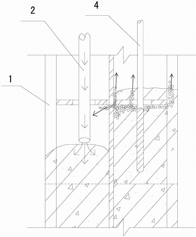
图6为本混凝土浇筑方法中,型钢柱相邻两个浇筑区域内分别进行捣入混凝土和振捣混凝土时的原理示意图。Fig. 6 is a schematic diagram of the principle of pouring concrete and vibrating concrete respectively in two adjacent pouring areas of the steel column in the concrete pouring method.
图7为本混凝土浇筑方法中,振动棒在型钢柱加劲肋钢板的板面对四个浇筑区域内的混凝土进行平衡第二次复振的原理示意图。Fig. 7 is a schematic diagram of the principle of the vibrating rod balancing the concrete in the four pouring areas on the slab face of the steel column stiffener steel plate in the concrete pouring method for the second re-vibration.
图8为本混凝土浇筑方法中,在型钢梁一侧捣入混凝土并进行振捣时的原理示意图。Fig. 8 is a schematic diagram of the principle when concrete is poured into one side of the shaped steel beam and vibrated in the concrete pouring method.
图9为本混凝土浇筑方法中,对型钢梁内的混凝土进行最终振捣时的原理示意图。Fig. 9 is a schematic diagram of the principle of final vibration of the concrete in the steel beam in the concrete pouring method.
具体实施方式 Detailed ways
下面结合实施例及附图,对本发明作进一步的详细说明,但本发明的实施方式不限于此。The present invention will be further described in detail below in conjunction with the embodiments and the accompanying drawings, but the embodiments of the present invention are not limited thereto.
实施例Example
本实施例一种高层建筑型钢混凝土组合结构用的混凝土浇筑方法,包括以下步骤:The concrete pouring method that a kind of high-rise building steel-concrete composite structure of the present embodiment is used comprises the following steps:
(1)安装型钢柱、型钢梁、钢筋和模板;(1) Install shaped steel columns, shaped steel beams, steel bars and templates;
(2)如图1所示,在型钢柱1中安装混凝土浇筑串筒2;(2) As shown in Figure 1, install the
(3)在型钢柱的柱底注入厚度为50~100mm的水泥砂浆;(3) Inject cement mortar with a thickness of 50~100mm at the bottom of the steel column;
(4)按照型钢柱的截面分格,采用同时浇筑进度错位推进的方式,按各分格顺序通过混凝土浇筑串筒2向型钢柱中捣入混凝土,同时通过振动棒4对混凝土进行振捣,直至型钢柱内的混凝土高度比型钢梁的底面高出10~20mm为止;具体为:(4) According to the cross-section division of the steel column, adopt the method of shifting the pouring progress at the same time, pour concrete into the steel column through the
(4-1)如图2所示,根据十字结构,型钢柱的截面分为4格,分别与加劲肋钢板3的4个区域对应,如图1所示,相邻两个加劲肋钢板3之间的型钢柱段内分成4个浇筑区域;(4-1) As shown in Figure 2, according to the cross structure, the section of the steel column is divided into 4 grids, corresponding to the 4 regions of the
(4-2)如图6所示,针对一个型钢柱段,先通过混凝土浇筑串筒2向第一个浇筑区域捣入高度为400~500mm的混凝土;(4-2) As shown in Figure 6, for a section of steel section, first pour concrete with a height of 400~500mm into the first pouring area through the
(4-3)第一个浇筑区域内捣入混凝土后,通过振动棒4对第一个浇筑区域内的混凝土进行振捣,同时通过混凝土浇筑串筒2向第二个浇筑区域捣入高度为400~500mm的混凝土;(4-3) After the concrete is poured into the first pouring area, vibrate the concrete in the first pouring area with the vibrating
(4-4)振捣第二个浇筑区域内的混凝土和捣入第三个浇筑区域内的混凝土同时进行,振捣第三个浇筑区域内的混凝土和捣入第四个浇筑区域内的混凝土同时进行;(4-4) Vibrate the concrete in the second pouring area and the concrete in the third pouring area at the same time, vibrate the concrete in the third pouring area and the concrete in the fourth pouring area Simultaneously;
(4-5)第四个浇筑区域内的混凝土捣入完成后,通过振动棒对第四个浇筑区域内的混凝土进行振捣;(4-5) After the concrete in the fourth pouring area is rammed in, vibrate the concrete in the fourth pouring area with a vibrating rod;
(4-6)通过振动棒分别对四个浇筑区域及型钢柱四个侧面各区之间混凝土流动结合处的混凝土进行第二次复振动;(4-6) Vibrating rods are used to carry out the second complex vibration of the concrete in the four pouring areas and the concrete flow joints between the four sides of the steel column;
(4-7)如图7所示,重复步骤(4-2)至(4-6),直至型钢柱内的混凝土高度比型钢柱段面的加劲肋钢板板面高出100~150mm为止,然后在加劲肋钢板的板面对混凝土第二次复振动;(4-7) As shown in Figure 7, repeat steps (4-2) to (4-6) until the height of the concrete inside the steel column is 100~150mm higher than that of the steel plate with stiffeners on the section surface of the steel column. Then the concrete is vibrated for the second time on the face of the stiffened steel plate;
(4-8)重复步骤(4-2)至(4-7),直至型钢柱内的混凝土高度比型钢梁的底面高出10~20mm为止;(4-8) Repeat steps (4-2) to (4-7) until the concrete height in the steel column is 10~20mm higher than the bottom surface of the steel beam;
步骤(4-2)至(4-5)的过程中,型钢柱浇筑时各浇筑区域内混凝土的流动方向如图4中的箭头所示;In the process of steps (4-2) to (4-5), the flow direction of concrete in each pouring area when the steel column is poured is shown by the arrow in Figure 4;
步骤(4-6)过程中,型钢柱浇筑时第二次振捣是每浇筑完一节高度为400~500mm混凝土时按截面分格区的混凝土第二次复振动,在柱的侧面各个区域混凝土流动结合位置来回振捣和将截面各区域混凝土振捣平衡,并确认混凝土内的气体已全部排出,如图5所示,其中5及其相应箭头为第二次复振动第一遍振捣的路线,6及其相应箭头为第二次复振动的第二遍振捣的路线;In the process of step (4-6), the second vibration during the pouring of the steel column is the second complex vibration of the concrete divided by the cross-section when each section of concrete with a height of 400~500mm is poured. In each area on the side of the column Vibrate back and forth at the joint position of the concrete flow and vibrate the concrete in each area of the section to balance, and confirm that the gas in the concrete has been completely discharged, as shown in Figure 5, where 5 and its corresponding arrows are the first vibration of the second complex vibration The route of , 6 and its corresponding arrows are the route of the second vibration of the second complex vibration;
步骤(4-7)中,型钢柱内的混凝土高度比型钢柱内加劲肋钢板面高出100~150mm时,对加劲肋钢板的板面进行第二次复振动。如图7所示,通过振动棒4对型钢柱的截面的4个区域内加劲肋钢板的浇筑孔12及柱侧面各个分区混凝土流动结合位置来回反复振动,将截面各个区域内的混凝土振捣平衡,并确认型钢柱加劲肋钢板底方阴角处混凝土内的气体已全部排出。In step (4-7), when the height of the concrete inside the shaped steel column is 100-150 mm higher than the surface of the stiffened steel plate in the shaped steel column, the second complex vibration is performed on the plate surface of the stiffened steel plate. As shown in Figure 7, the pouring
检查混凝土内的气体是否全部排出是在振动时,通过观察混凝土面是否还有气体水泡出现,直到在振动时混凝土面的气体水气泡排出干净消失为止,混凝土的密实度达到质量要求;Check whether all the gas in the concrete is discharged during vibration, by observing whether there are gas bubbles on the concrete surface, until the gas water bubbles on the concrete surface are completely discharged and disappear during vibration, and the compactness of the concrete meets the quality requirements;
(5)如图3所示,沿型钢梁7的纵轴线方向,按型钢梁的纵向分格,型钢梁的两侧分别为第一侧8和第二侧9,如图8所示,先在型钢梁的第一侧8底边捣入高度为300~400mm的混凝土,并采用振动棒4振捣混凝土,使混凝土通过型钢梁的底部流动至型钢梁的第二侧9底边,检查并确认混凝土内的气体已全部排出;采用高低错位的方式,交替在第二侧9和第一侧8内捣入混凝土并振动,同时重复检查并确认混凝土内的气体已全部排出,直至第一侧8和第二侧9内的混凝土均高出型钢梁13的梁面钢板面30mm~50mm为止,重复对混凝土振动检查并确认型钢梁面钢板底部与梁腹板及加劲肋钢板合成的方阴角处混凝土内的气体已全部排出为止;(5) As shown in Figure 3, along the direction of the longitudinal axis of the shaped steel beam 7, according to the longitudinal division of the shaped steel beam, the two sides of the shaped steel beam are respectively the first side 8 and the second side 9, as shown in Figure 8 As shown, concrete with a height of 300~400mm is pounded into the bottom edge of the first side 8 of the shaped steel beam first, and the vibrating rod 4 is used to vibrate the concrete, so that the concrete flows through the bottom of the shaped steel beam to the second side of the shaped steel beam 9 bottom edge, check and confirm that all the gas in the concrete has been discharged; adopt the method of high and low dislocation, alternately pour concrete into the second side 9 and the first side 8 and vibrate, and at the same time repeatedly check and confirm that the gas in the concrete has been completely discharged until the concrete in the first side 8 and the second side 9 is 30mm~50mm higher than the beam surface steel plate surface of the shaped steel beam 13, repeat the vibration inspection of the concrete and confirm that the bottom of the shaped steel beam surface steel plate and the beam web and Until all the gas in the concrete at the corners of the squares made of stiffened steel plates has been exhausted;
该过程具体为:The process is specifically:
(5-1)沿型钢梁的纵轴线方向,型钢梁的截面纵向分为左右2格,分别与型钢梁截面的“工”字形两侧区域相对应;(5-1) Along the longitudinal axis of the steel beam, the section of the steel beam is longitudinally divided into two grids on the left and right, corresponding to the two sides of the "I" shape of the steel beam section;
(5-2)如图8所示,先在型钢梁的第一侧8底边捣入高度为300~400mm的混凝土,并采用振动棒振捣混凝土,使混凝土通过型钢梁的底部流动至型钢梁的第二侧9底边,检查并确认混凝土内的气体已全部排出;(5-2) As shown in Figure 8, first pour concrete with a height of 300~400mm into the bottom of the
(5-3)采用高低错位的方式,交替在第二侧9和第一侧8内捣入混凝土并振动,同时重复检查并确认混凝土内的气体已全部排出,直至第一侧8和第二侧9内的混凝土均高出型钢梁的梁面30mm~50mm为止;如图9所示,最后可两侧同时进行振捣,重复对混凝土振捣并检查确认型钢梁面钢板底部与梁腹板及加劲肋钢板合成的方阴角处混凝土内的气体已全部排出为止;(5-3) Use the method of high and low dislocation, alternately pour concrete into the
检查混凝土内的气体是否全部排出时,是在振捣时观察混凝土表面是否还有气体水泡出现,直到在振捣时混凝土表面的气体水气泡排出干净消失为止,混凝土的密实度达到质量要求。When checking whether the gas in the concrete is completely discharged, it is to observe whether there are gas bubbles on the surface of the concrete during vibration, until the gas and water bubbles on the surface of the concrete are completely discharged and disappear during vibration, and the compactness of the concrete meets the quality requirements.
上述施工方法中,步骤(2)中混凝土浇筑串筒2用薄钢板制成,直径D1比型钢柱加劲肋钢板上预留的浇筑孔直径D小约40cm,即D=150~200mm,D1=110~160mm。混凝土浇筑串筒的长度可达4~6m,上端为活动连接的漏斗型入料口,可从入料口直接将混凝土浇灌入串筒2。操作时用长钢丝绳扣紧串筒上端两侧吊环,将串筒2垂直穿过型钢柱加劲肋钢板预留浇筑孔12插入至混凝土浇筑位置。当柱节是两至三楼层高时在中间层浇筑混凝土,可将泵送混凝土泵管的出料口软管从型钢柱侧面翼缘钢板开口处插入混凝土浇筑串筒2的活接口将混凝土灌入串筒2内。In the above construction method, in step (2), the concrete pouring
步骤(3)中,水泥砂浆中各成份的含量与混凝土中所含水泥砂浆各成份的含量相同。In step (3), the content of each component in the cement mortar is the same as the content of each component of the cement mortar contained in the concrete.
步骤(4)中,同时浇筑进度错位推进方式为:混凝土浇筑和跟随着的混凝土振动按照型钢柱的截面分格的顺序进行,在柱截面的前一个分格内通过混凝土浇筑串筒2捣入混凝土,同时在后一个分格内通过振动棒4对混凝土进行振捣的工艺。In step (4), the dislocation advancement method of simultaneous pouring progress is as follows: concrete pouring and subsequent concrete vibration are carried out in the order of the section divisions of the steel column, and the
步骤(5)中所述高低错位的方式为:先在型钢梁的第一侧8底边捣入高度为300~400mm的混凝土,并振捣使混凝土通过型钢梁的底部流动至型钢梁的第二侧9底边,并确认底部混凝土内的气体已全部排出;然后在型钢梁的第二侧9捣入混凝土并振动,同时重复检查并确认底部混凝土内的气体已全部排出,直至第二侧9的混凝土高度比第一侧8高出100mm;再在型钢梁的第一侧8捣入混凝土并振动,同时重复检查并确认底部混凝土内的气体已全部排出,直至第一侧的混凝土高度比第二侧高出100mm;重复在第二侧9和第一侧8轮流捣入混凝土并振动,直至第一侧8和第二侧9内的混凝土均高出型钢梁的梁面30mm~50mm为止,最后可两侧同时进行振捣,重复对混凝土振动,检查并确认型钢梁面钢板底部与梁腹板及加劲肋钢板合成的方阴角处混凝土内的气体已全部排出为止。The method of height dislocation described in step (5) is as follows: first, pour concrete with a height of 300~400mm into the bottom edge of the
如图1所示,所述型钢柱1中部为2个腹钢板相互垂直构成的十字结构10,十字结构的4个端部分别设置翼缘钢板11,型钢梁与翼缘钢板垂直连接;型钢柱内设有多个加劲肋钢板3,各加劲肋钢板分别与十字结构垂直设置,十字结构将加劲肋钢板分成的4个区域内分别预留有混凝土浇筑串筒孔12。As shown in Figure 1, the middle part of the shaped
如图3所示,所述型钢梁7的截面为“工”字形,包括顶板13、腹板14和底板15,顶板和底板分别设于腹板的上下两侧,腹板的上部和下部设置螺栓孔,螺栓孔处通过螺栓与型钢柱固定连接,底板下方通过梁定位牛腿与型钢柱进行定位。(螺栓孔及梁定位牛腿在图中未示出)。As shown in Figure 3, the cross-section of the shaped
所述步骤(5)中,型钢梁的混凝土浇筑是在型钢柱的混凝土浇筑完成后,隔1~1.5小时待型钢柱内混凝土沉实后再进行。In the step (5), the concrete pouring of the shaped steel beam is performed after the concrete pouring of the shaped steel column is completed, and then the concrete in the shaped steel column is settled after 1-1.5 hours.
本高层建筑型钢混凝土组合结构的混凝土浇筑方法主要针对型钢柱和型钢梁分别浇筑。对型钢柱进行浇筑时,采用同时浇筑进度错位推进的方式将型钢柱进行分区域浇筑和振捣;对型钢梁进行浇筑时,采用纵向分格的方式将型钢梁分两侧进行高低错位浇筑和振捣。从而使型钢梁和型钢柱内的阴角处气体完全排出,保证混凝土的密实度。The concrete pouring method of the steel-concrete composite structure of the high-rise building is mainly aimed at pouring the steel columns and the steel beams respectively. When pouring the steel columns, the steel columns are poured and vibrated in different areas by dislocation of the pouring progress at the same time; when the steel beams are poured, the steel beams are divided into two sides for high and low displacement by longitudinal division Pouring and vibrating. In this way, the gas at the corners of the shaped steel beams and shaped steel columns can be completely discharged to ensure the compactness of the concrete.
如上所述,便可较好地实现本发明,上述实施例仅为本发明的较佳实施例,并非用来限定本发明的实施范围;即凡依本发明内容所作的均等变化与修饰,都为本发明权利要求所要求保护的范围所涵盖。As mentioned above, the present invention can be better realized. The above-mentioned embodiment is only a preferred embodiment of the present invention, and is not used to limit the scope of the present invention; Covered by the scope of protection required by the claims of the present invention.
Claims (9)
Priority Applications (1)
| Application Number | Priority Date | Filing Date | Title |
|---|---|---|---|
| CN201210220397.6A CN102777034B (en) | 2012-06-28 | 2012-06-28 | Concrete pouring method for combined structural steel and concrete structure of high-rise building |
Applications Claiming Priority (1)
| Application Number | Priority Date | Filing Date | Title |
|---|---|---|---|
| CN201210220397.6A CN102777034B (en) | 2012-06-28 | 2012-06-28 | Concrete pouring method for combined structural steel and concrete structure of high-rise building |
Publications (2)
| Publication Number | Publication Date |
|---|---|
| CN102777034A true CN102777034A (en) | 2012-11-14 |
| CN102777034B CN102777034B (en) | 2014-06-25 |
Family
ID=47122128
Family Applications (1)
| Application Number | Title | Priority Date | Filing Date |
|---|---|---|---|
| CN201210220397.6A Expired - Fee Related CN102777034B (en) | 2012-06-28 | 2012-06-28 | Concrete pouring method for combined structural steel and concrete structure of high-rise building |
Country Status (1)
| Country | Link |
|---|---|
| CN (1) | CN102777034B (en) |
Cited By (5)
| Publication number | Priority date | Publication date | Assignee | Title |
|---|---|---|---|---|
| CN102936953A (en) * | 2012-11-23 | 2013-02-20 | 中国建筑第八工程局有限公司 | Construction method of bridging-arm stiffened steel structure template |
| CN103510702A (en) * | 2013-09-29 | 2014-01-15 | 广州建筑股份有限公司 | Concrete-filled steel tube column needle type concrete pouring construction method |
| CN109795020A (en) * | 2019-03-21 | 2019-05-24 | 徐州工程学院 | A kind of preparation method of high carbonation resistance reinforced concrete |
| CN110005053A (en) * | 2019-04-18 | 2019-07-12 | 中南大学 | A sub-structure assembled frame structure and its construction method |
| CN115717480A (en) * | 2022-12-09 | 2023-02-28 | 中国建筑第二工程局有限公司 | Concrete pouring method for narrow space of cavity wall |
Citations (9)
| Publication number | Priority date | Publication date | Assignee | Title |
|---|---|---|---|---|
| JPH0657956A (en) * | 1992-07-31 | 1994-03-01 | Maeda Corp | Construction of concrete structure |
| JPH06146394A (en) * | 1992-11-11 | 1994-05-27 | Shimizu Corp | Structure of reinforced concrete column and construction method thereof |
| JPH11303397A (en) * | 1998-04-22 | 1999-11-02 | Fujita Corp | Construction method of reinforced concrete building |
| CN201172968Y (en) * | 2008-04-17 | 2008-12-31 | 河南泰宏房屋营造有限公司 | Grid conductor for slant concrete placement |
| CN201268850Y (en) * | 2008-09-03 | 2009-07-08 | 中冶成工建设有限公司工程技术分公司 | Concrete non-return apparatus for steel column reverse pouring concrete casting construction |
| CN101845889A (en) * | 2009-12-24 | 2010-09-29 | 上海市第七建筑有限公司 | Concrete casting and tamping method of steel tube concrete structure column |
| CN201695697U (en) * | 2010-05-25 | 2011-01-05 | 中建三局建设工程股份有限公司 | Beating and vibrating construction structure of special-shaped reinforced concrete member |
| CN102116052A (en) * | 2009-12-30 | 2011-07-06 | 贵阳铝镁设计研究院 | Method for pouring reinforced concrete beam of operating platform |
| CN202645011U (en) * | 2012-07-11 | 2013-01-02 | 上海建工五建集团有限公司 | Pumping device for super high-rise building steel tube concrete |
-
2012
- 2012-06-28 CN CN201210220397.6A patent/CN102777034B/en not_active Expired - Fee Related
Patent Citations (9)
| Publication number | Priority date | Publication date | Assignee | Title |
|---|---|---|---|---|
| JPH0657956A (en) * | 1992-07-31 | 1994-03-01 | Maeda Corp | Construction of concrete structure |
| JPH06146394A (en) * | 1992-11-11 | 1994-05-27 | Shimizu Corp | Structure of reinforced concrete column and construction method thereof |
| JPH11303397A (en) * | 1998-04-22 | 1999-11-02 | Fujita Corp | Construction method of reinforced concrete building |
| CN201172968Y (en) * | 2008-04-17 | 2008-12-31 | 河南泰宏房屋营造有限公司 | Grid conductor for slant concrete placement |
| CN201268850Y (en) * | 2008-09-03 | 2009-07-08 | 中冶成工建设有限公司工程技术分公司 | Concrete non-return apparatus for steel column reverse pouring concrete casting construction |
| CN101845889A (en) * | 2009-12-24 | 2010-09-29 | 上海市第七建筑有限公司 | Concrete casting and tamping method of steel tube concrete structure column |
| CN102116052A (en) * | 2009-12-30 | 2011-07-06 | 贵阳铝镁设计研究院 | Method for pouring reinforced concrete beam of operating platform |
| CN201695697U (en) * | 2010-05-25 | 2011-01-05 | 中建三局建设工程股份有限公司 | Beating and vibrating construction structure of special-shaped reinforced concrete member |
| CN202645011U (en) * | 2012-07-11 | 2013-01-02 | 上海建工五建集团有限公司 | Pumping device for super high-rise building steel tube concrete |
Cited By (8)
| Publication number | Priority date | Publication date | Assignee | Title |
|---|---|---|---|---|
| CN102936953A (en) * | 2012-11-23 | 2013-02-20 | 中国建筑第八工程局有限公司 | Construction method of bridging-arm stiffened steel structure template |
| CN102936953B (en) * | 2012-11-23 | 2015-03-18 | 中国建筑第八工程局有限公司 | Construction method of a bridging-arm stiffened steel structure template |
| CN103510702A (en) * | 2013-09-29 | 2014-01-15 | 广州建筑股份有限公司 | Concrete-filled steel tube column needle type concrete pouring construction method |
| CN103510702B (en) * | 2013-09-29 | 2016-01-20 | 广州建筑股份有限公司 | Steel core concrete column pin type concrete pouring construction method |
| CN109795020A (en) * | 2019-03-21 | 2019-05-24 | 徐州工程学院 | A kind of preparation method of high carbonation resistance reinforced concrete |
| CN109795020B (en) * | 2019-03-21 | 2021-04-23 | 徐州工程学院 | A kind of preparation method of high carbonation resistance reinforced concrete |
| CN110005053A (en) * | 2019-04-18 | 2019-07-12 | 中南大学 | A sub-structure assembled frame structure and its construction method |
| CN115717480A (en) * | 2022-12-09 | 2023-02-28 | 中国建筑第二工程局有限公司 | Concrete pouring method for narrow space of cavity wall |
Also Published As
| Publication number | Publication date |
|---|---|
| CN102777034B (en) | 2014-06-25 |
Similar Documents
| Publication | Publication Date | Title |
|---|---|---|
| CN103924711B (en) | Construction Technology of Prefabricated Grid Shear Wall Structural System | |
| CN103510702B (en) | Steel core concrete column pin type concrete pouring construction method | |
| CN109083275B (en) | Prefabricated column and one-piece prefabricated beam-slab assembly node and its construction method | |
| CN103195247B (en) | Saddle-shaped hyperboloidal concrete slab construction method | |
| CN102777034B (en) | Concrete pouring method for combined structural steel and concrete structure of high-rise building | |
| CN105952061B (en) | Precast shear wall steel reinforcement cage component, column steel reinforcement cage component and manufacture assembly method | |
| CN102877649B (en) | Prefabricated concrete structure interlayer pouring construction method | |
| CN108222540A (en) | The load bearing wall that brick mix structure is changed to frame structure changes girder construction and construction method | |
| CN106013455A (en) | Prefabricated combination reinforcement cage member and reinforcement arrangement assembling method thereof | |
| CN111663659B (en) | Staggered floor synchronous construction method | |
| CN105332455B (en) | A kind of metal filled case of permeability type | |
| CN103590602A (en) | Method for constructing cast-in-site concrete hollow floor systems | |
| CN103850363A (en) | Prefabricated through-hole assembled reinforced concrete shear wall and its construction method | |
| CN108867860A (en) | A kind of precast reinforced concrete beam plate body system and prefabricated rod structure entirety assembling constructing method | |
| CN112832417A (en) | Honeycomb hollow grid tubular double steel plate concrete composite shear wall and preparation method thereof | |
| CN110905113A (en) | Construction method of large-span concrete dome structure | |
| CN103061509B (en) | Construction process for implementing post-cast strip casting by post-cast strip stiff steel pipe support system | |
| CN211499326U (en) | A synchronous construction structure of concrete infill wall and cast-in-place structure | |
| CN205894670U (en) | Template structure for concrete joint construction between floors | |
| CN113463653B (en) | A construction method for vertical section type dismantling of inner support | |
| CN204919605U (en) | Prefabricated assembled reinforced concrete utility tunnel and production mould thereof | |
| CN206053132U (en) | Precast reinforced cage component, shear wall and diaphram wall | |
| CN105239675B (en) | A kind of concrete filled steel tube switching node structure and its construction method | |
| CN112127527A (en) | A kind of cast-in-place lightweight partition wall and pouring method | |
| CN110748221A (en) | A prefabricated pool guide wall |
Legal Events
| Date | Code | Title | Description |
|---|---|---|---|
| C06 | Publication | ||
| PB01 | Publication | ||
| C10 | Entry into substantive examination | ||
| SE01 | Entry into force of request for substantive examination | ||
| C14 | Grant of patent or utility model | ||
| GR01 | Patent grant | ||
| CF01 | Termination of patent right due to non-payment of annual fee |
Granted publication date: 20140625 |
|
| CF01 | Termination of patent right due to non-payment of annual fee |