CN102811896A - Steering device - Google Patents

Steering device Download PDF

Info

Publication number
CN102811896A
CN102811896A CN2012800002167A CN201280000216A CN102811896A CN 102811896 A CN102811896 A CN 102811896A CN 2012800002167 A CN2012800002167 A CN 2012800002167A CN 201280000216 A CN201280000216 A CN 201280000216A CN 102811896 A CN102811896 A CN 102811896A
Authority
CN
China
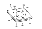
Prior art keywords
vehicle body
bracket
guide
guide pin
steering column
Prior art date
Legal status (The legal status is an assumption and is not a legal conclusion. Google has not performed a legal analysis and makes no representation as to the accuracy of the status listed.)
Granted
Application number
CN2012800002167A
Other languages
Chinese (zh)
Other versions
CN102811896B (en
Inventor
石井徹
田中嵩悠
Current Assignee (The listed assignees may be inaccurate. Google has not performed a legal analysis and makes no representation or warranty as to the accuracy of the list.)
NSK Ltd
Original Assignee
NSK Ltd
Priority date (The priority date is an assumption and is not a legal conclusion. Google has not performed a legal analysis and makes no representation as to the accuracy of the date listed.)
Filing date
Publication date
Application filed by NSK Ltd filed Critical NSK Ltd
Publication of CN102811896A publication Critical patent/CN102811896A/en
Application granted granted Critical
Publication of CN102811896B publication Critical patent/CN102811896B/en
Expired - Fee Related legal-status Critical Current
Anticipated expiration legal-status Critical

Links

Images

Classifications

    • BPERFORMING OPERATIONS; TRANSPORTING
    • B62LAND VEHICLES FOR TRAVELLING OTHERWISE THAN ON RAILS
    • B62DMOTOR VEHICLES; TRAILERS
    • B62D1/00Steering controls, i.e. means for initiating a change of direction of the vehicle
    • B62D1/02Steering controls, i.e. means for initiating a change of direction of the vehicle vehicle-mounted
    • B62D1/16Steering columns
    • B62D1/18Steering columns yieldable or adjustable, e.g. tiltable
    • B62D1/19Steering columns yieldable or adjustable, e.g. tiltable incorporating energy-absorbing arrangements, e.g. by being yieldable or collapsible
    • B62D1/195Yieldable supports for the steering column
    • BPERFORMING OPERATIONS; TRANSPORTING
    • B60VEHICLES IN GENERAL
    • B60RVEHICLES, VEHICLE FITTINGS, OR VEHICLE PARTS, NOT OTHERWISE PROVIDED FOR
    • B60R21/00Arrangements or fittings on vehicles for protecting or preventing injuries to occupants or pedestrians in case of accidents or other traffic risks
    • B60R21/02Occupant safety arrangements or fittings, e.g. crash pads
    • B60R21/09Control elements or operating handles movable from an operative to an out-of-the way position, e.g. pedals, switch knobs, window cranks

Landscapes

  • Engineering & Computer Science (AREA)
  • Mechanical Engineering (AREA)
  • Chemical & Material Sciences (AREA)
  • Combustion & Propulsion (AREA)
  • Transportation (AREA)
  • Steering Controls (AREA)
  • Power Steering Mechanism (AREA)

Abstract

A steering device is provided with: a steering column 46; a steering column 42 fitted in a destructively movable manner to a steering column 46; a bracket 21 fixed to the vehicle body so as to be able to be detached together with the steering column 42 by an impact force at the time of a secondary collision; a guide bracket 61 fixed to the steering column 46 and having a guide groove 63 formed therein; and a pin 71 fixed to the bracket 21, guided by the guide groove 63, and movable together with the bracket 21; wherein: the guide bracket 61 has a flat plate portion 61d not in contact with the bracket 21, and the flat plate portion 61d is formed with a guide groove 63; a head portion 713 having a larger diameter than the shaft portion at an upper end of the pin 71; the steering device includes a gap setting unit that comes into contact with the upper surface of the bracket 21 when the pin 71 is fixed to the bracket 21, and sets the length of the gap between the lower surface of the head 713 and the upper surface of the bracket 21 to a predetermined value. This makes it possible to provide a steering apparatus capable of highly accurately adjusting the separation force when the steering column 42 separates to the vehicle body front side by the impact force at the time of a secondary collision, and facilitating the adjustment work of the separation force.

Description

转向装置Steering device

技术领域 technical field

本实施方式涉及转向装置,特别涉及在二次碰撞时转向盘向车体前方侧毁损(collapse)移动而吸收冲击载荷的转向装置。The present embodiment relates to a steering device, and particularly relates to a steering device in which a steering wheel collapses and moves toward the front side of a vehicle body to absorb an impact load during a secondary collision.

背景技术 Background technique

作为在二次碰撞时转向盘向车体前方侧毁损移动而吸收冲击载荷的转向装置,有特开2005-219641号公报所示的转向装置。特开2005-219641号公报所示的转向装置,通过车体安装托架在车体上安装有上部转向柱和下部转向柱,并且通过二次碰撞时的预定的冲击力,使上部转向柱从车体安装托架脱离而向车体前方侧毁损移动。As a steering device in which the steering wheel is damaged and moves toward the front side of the vehicle body to absorb the impact load during a secondary collision, there is a steering device disclosed in JP-A-2005-219641. In the steering device shown in JP-A-2005-219641, the upper steering column and the lower steering column are installed on the vehicle body through the vehicle body mounting bracket, and through the predetermined impact force during the secondary collision, the upper steering column is moved from The vehicle body mounting bracket is detached and damaged and moved to the front side of the vehicle body.

现有技术文献prior art literature

专利文献patent documents

专利文献1:特开2005-219641号公报Patent Document 1: JP-A-2005-219641

发明内容 Contents of the invention

发明所要解决的问题The problem to be solved by the invention

在特开2005-219641号公报所示的转向装置中,经由摩擦系数小的镀膜板在车体安装托架上紧固上部转向柱的倾斜托架,通过二次碰撞时的预定的冲击力,使上部转向柱以及倾斜托架顺利地从车体安装托架脱离。但是,因为是通过螺栓在车体安装托架上固定镀膜板,所以根据螺栓的紧固转矩,上部转向柱以及倾斜托架的脱离力变化。因此,需要将螺栓的紧固转矩调整为预定的值,存在下述问题:组装时间变长,并且镀膜板的组装要求熟练。In the steering device shown in JP-A-2005-219641, the tilt bracket of the upper steering column is fastened to the vehicle body mounting bracket via a coated plate with a small friction coefficient, and through a predetermined impact force at the time of a secondary collision, Smoothly disengage the upper steering column and tilt bracket from the body mounting bracket. However, since the coating plate is fixed to the vehicle body mounting bracket with bolts, the detachment force of the upper steering column and the tilt bracket changes according to the tightening torque of the bolts. Therefore, it is necessary to adjust the tightening torque of the bolts to a predetermined value, and there are problems in that assembly time becomes longer and skill is required for assembly of the coated plate.

用于解决问题的方案solutions to problems

本发明的目的在于提供能够高精度地调整上部转向柱因二次碰撞时的冲击力而向车体前方侧脱离时的脱离力、且脱离力的调整作业容易的转向装置。It is an object of the present invention to provide a steering device that can accurately adjust the disengagement force when the upper steering column disengages toward the front side of the vehicle body due to the impact force of a secondary collision, and that facilitates adjustment of the disengagement force.

上述目的通过下面的技术方案解决。即,本发明提供一种转向装置,该转向装置具备:下部转向柱,其车体前方侧能够固定于车体;上部转向柱,其能够向车体前方侧毁损移动地嵌合于所述下部转向柱,并且将安装有转向盘的转向轴轴支撑得能够转动;上部托架,其能够以可脱离的方式安装于车体,所述脱离的方式是能够通过二次碰撞时的预定的冲击力与所述上部转向柱一起向车体前方侧脱离;引导托架,其将车体前方侧固定于所述下部转向柱,沿着所述下部转向柱向车体后方侧延伸,形成有在二次碰撞时对所述上部转向柱的毁损移动进行引导的引导槽;以及引导销,其固定于所述上部托架,由所述引导槽对轴部的外周面进行引导而能够与上部托架一起移动;其特征在于:所述引导托架具有与所述上部托架不接触的平板部,在该平板部形成有所述引导槽;所述引导销在该引导销的轴部的上端具有直径比该轴部大的头部;该转向装置具备间隙设定部,该间隙设定部在已将所述引导销固定于所述上部托架时,与所述上部托架的上表面接触而将所述头部的下表面与上部托架的上表面之间的间隙的长度设定为预定的值。The above object is solved by the following technical solutions. That is, the present invention provides a steering device including: a lower steering column capable of being fixed to the vehicle body at the front side of the vehicle body; The steering column, which supports the steering shaft on which the steering wheel is mounted so as to be rotatable; the upper bracket, which can be installed on the vehicle body in a detachable manner through a predetermined impact during a secondary collision together with the upper steering column to the front side of the vehicle body; the guide bracket, which fixes the front side of the vehicle body to the lower steering column, extends to the rear side of the vehicle body along the lower steering column, forming a a guide groove for guiding damage and movement of the upper steering column during a secondary collision; The guide bracket moves together; it is characterized in that: the guide bracket has a flat plate that is not in contact with the upper bracket, and the guide groove is formed on the flat plate; the guide pin is on the upper end of the shaft portion of the guide pin having a head with a diameter larger than the shaft portion; the steering device is provided with a gap setting portion which, when the guide pin is fixed to the upper bracket, is in contact with the upper surface of the upper bracket contact to set the length of the gap between the lower surface of the head and the upper surface of the upper bracket to a predetermined value.

根据本发明的优选的方式,提供一种转向装置,其特征在于:具备合成树脂制的分隔件,该分隔件外嵌于所述引导销的轴部外周面,该分隔件的外周面与所述引导槽接触而能够毁损移动;在所述分隔件的外周面,形成有与所述引导槽接触而能够毁损移动的圆筒部。According to a preferred aspect of the present invention, there is provided a steering device characterized by comprising a spacer made of synthetic resin fitted on the outer peripheral surface of the shaft portion of the guide pin, and the outer peripheral surface of the spacer is in contact with the outer peripheral surface of the guide pin. The guide groove can be damaged and moved; and the outer peripheral surface of the separator is formed with a cylindrical part that can be damaged and moved in contact with the guide groove.

根据本发明的优选的方式,提供一种转向装置,其特征在于:在所述分隔件的外周面,形成有与所述引导槽接触而能够毁损移动且相互平行的2个平面部。According to a preferred aspect of the present invention, there is provided a steering device characterized in that on the outer peripheral surface of the separator, two planar portions parallel to each other are formed in contact with the guide groove so as to be destructible and movable.

根据本发明的优选的方式,提供一种转向装置,其特征在于:具备形成于所述分隔件的上端、直径比分隔件的外周面大的凸缘部。According to a preferred aspect of the present invention, there is provided a steering device characterized by comprising a flange portion formed on an upper end of the partition and having a diameter larger than an outer peripheral surface of the partition.

根据本发明的优选的方式,提供一种转向装置,其特征在于:所述分隔件的凸缘部形成为圆盘状。According to a preferred aspect of the present invention, there is provided a steering device characterized in that the flange portion of the separator is formed in a disk shape.

根据本发明的优选的方式,提供一种转向装置,其特征在于:所述分隔件的凸缘部形成为矩形形状。According to a preferred aspect of the present invention, there is provided a steering device characterized in that the flange portion of the separator is formed in a rectangular shape.

根据本发明的优选的方式,提供一种转向装置,其特征在于:具备凸部,该凸部向车体上方侧突出地形成于所述凸缘部的上表面,被所述头部的下表面按压而能够塑性变形。According to a preferred aspect of the present invention, there is provided a steering device characterized by comprising a convex portion formed on the upper surface of the flange portion so as to protrude toward the upper side of the vehicle body and received by the lower portion of the head portion. The surface can be plastically deformed by pressing.

根据本发明的优选的方式,提供一种转向装置,其特征在于:所述凸缘部的所述凸部的用与所述分隔件的中心轴线正交的平面切断出的剖面面积向车体上方侧变小。According to a preferred aspect of the present invention, there is provided a steering device characterized in that a cross-sectional area of the convex portion of the flange portion cut on a plane perpendicular to the central axis of the partition faces toward the vehicle body. The upper side becomes smaller.

根据本发明的优选的方式,提供一种转向装置,其特征在于:所述引导槽的车体前方侧的槽宽形成得比车体后方端的槽宽宽。According to a preferred aspect of the present invention, there is provided a steering device characterized in that the groove width of the vehicle body front side of the guide groove is formed wider than the groove width of the vehicle body rear end.

根据本发明的优选的方式,提供一种转向装置,其特征在于:通过折边加工,使所述引导托架的所述引导槽的周缘立起。According to a preferred aspect of the present invention, there is provided a steering device characterized in that the periphery of the guide groove of the guide bracket is raised by hemming.

根据本发明的优选的方式,提供一种转向装置,其特征在于:所述间隙设定部是一体形成于所述引导销的轴部的台阶面;所述引导销的沿着中心轴线的所述头部的下表面与所述台阶面的间隔,比所述分隔件的沿着中心轴线的长度大。According to a preferred aspect of the present invention, there is provided a steering device, characterized in that: the gap setting part is a stepped surface integrally formed on the shaft part of the guide pin; The distance between the lower surface of the head and the stepped surface is greater than the length of the partition along the central axis.

根据本发明的优选的方式,提供一种转向装置,其特征在于:所述间隙设定部是中空圆筒状的轴套,该轴套外嵌于所述引导销的轴部外周面,所述分隔件外嵌于该轴套的外周面;所述轴套的沿着中心轴线的长度比所述分隔件的沿着中心轴线的长度大。According to a preferred aspect of the present invention, there is provided a steering device, wherein the gap setting portion is a hollow cylindrical bushing, and the bushing is fitted on the outer peripheral surface of the shaft portion of the guide pin, so that The spacer is embedded on the outer peripheral surface of the shaft sleeve; the length of the shaft sleeve along the central axis is greater than the length of the spacer along the central axis.

本发明的转向装置具备:引导槽,其与毁损移动方向平行地形成于引导托架;引导销,其固定于上部托架,由引导槽对轴部的外周面进行引导而能够与上部托架一起移动直到车体前方侧的毁损移动端;头部,其以直径比引导销的轴部大的方式形成于轴部的上端,与引导托架的上表面抵接以限制上部托架的相对于毁损移动方向正交的方向的间隙;和间隙设定部,其在已将引导销固定于上部托架时,与上部托架的上表面抵接而将头部的下表面与上部托架的上表面之间的间隙的长度设定为预定的值。The steering device of the present invention is provided with: a guide groove, which is formed on the guide bracket parallel to the damage movement direction; Move together until the damaged moving end on the front side of the vehicle body; the head, which is formed on the upper end of the shaft portion with a diameter larger than the shaft portion of the guide pin, abuts against the upper surface of the guide bracket to limit the relative movement of the upper bracket A gap in a direction perpendicular to the damage movement direction; and a gap setting part, which abuts against the upper surface of the upper bracket when the guide pin has been fixed to the upper bracket to connect the lower surface of the head to the upper bracket. The length of the gap between the upper surfaces is set to a predetermined value.

因此,通过间隙设定部,能够限制上部托架相对于引导托架的、相对于毁损移动方向正交的方向的间隙,减小上部托架从引导托架脱离的载荷并且将该载荷设定为一定。Therefore, the gap setting part can limit the gap between the upper bracket and the guide bracket in the direction perpendicular to the damage movement direction, reduce the load of the upper bracket detached from the guide bracket and set the load. For sure.

另外,具备:合成树脂制的分隔件,该分隔件外嵌于引导销的轴部外周面,该分隔件的外周面与引导槽接触而能够毁损移动;凸缘部,该凸缘部形成于分隔件的上端,直径比分隔件的外周面大;和凸部,该凸部向车体上方侧突出地形成于凸缘部的上表面,被头部的下表面按压而能够塑性变形。In addition, it is equipped with: a spacer made of synthetic resin, the spacer is fitted on the outer peripheral surface of the shaft portion of the guide pin, the outer peripheral surface of the spacer is in contact with the guide groove and can be damaged and moved; a flange portion is formed on the The upper end of the spacer is larger in diameter than the outer peripheral surface of the spacer; and a convex portion is formed on the upper surface of the flange portion so as to protrude toward the upper side of the vehicle body and can be plastically deformed by being pressed by the lower surface of the head.

因此,仅通过将引导销固定于上部托架,引导销的头部的下表面按压凸部使其塑性变形、溃损,限制了相对于毁损移动方向正交的方向上的上部托架的间隙,所以不需要间隙的调整作业,组装不需要熟练,缩短了组装时间。Therefore, only by fixing the guide pin to the upper bracket, the lower surface of the head portion of the guide pin presses the convex portion to plastically deform and crumble, and the clearance of the upper bracket in the direction perpendicular to the moving direction of the damage is limited. , so there is no need to adjust the gap, and the assembly does not require skill, which shortens the assembly time.

另外,分隔件由合成树脂形成,所以能够减小引导槽与引导销之间的摩擦系数。因此,二次碰撞时的冲击能量的吸收性能稳定,能够高精度地设定冲击载荷的吸收特性。In addition, since the spacer is formed of synthetic resin, the coefficient of friction between the guide groove and the guide pin can be reduced. Therefore, the absorption performance of the impact energy at the time of the secondary collision is stable, and the absorption characteristic of the impact load can be set with high precision.

附图说明 Description of drawings

图1是表示采用本发明的第1实施方式或者第2实施方式的转向装置的整体的立体图。FIG. 1 is a perspective view showing the whole of a steering device according to a first embodiment or a second embodiment of the present invention.

图2是表示本发明的第1实施方式的转向装置的要部的立体图,是从车体后方侧的右上部观察的立体图。2 is a perspective view showing main parts of the steering device according to the first embodiment of the present invention, and is a perspective view viewed from the upper right portion on the rear side of the vehicle body.

图3是图2是引导托架的车体后方侧周边的俯视图。Fig. 3 is a plan view of the periphery of the vehicle body rear side of the guide bracket shown in Fig. 2 .

图4A是表示树脂制的分隔件与引导槽的接触部的图3的4A-4A剖视图,图4B是表示图4A的引导销单体的主视图。4A is a cross-sectional view taken along line 4A-4A of FIG. 3 showing the contact portion between the resin spacer and the guide groove, and FIG. 4B is a front view showing the guide pin alone of FIG. 4A .

图5是表示本发明的第1实施方式中的树脂制的分隔件的立体图。5 is a perspective view showing a resin-made separator in the first embodiment of the present invention.

图6是表示本发明的第1实施方式的变形例1中的树脂制的分隔件的立体图。6 is a perspective view showing a resin separator in Modification 1 of the first embodiment of the present invention.

图7是表示本发明的第1实施方式的变形例2中的树脂制的分隔件的立体图。7 is a perspective view showing a resin separator in Modification 2 of the first embodiment of the present invention.

图8A以及图8B是表示本发明的第1实施方式的变形例3中的树脂制的分隔件的立体图,图8A是从凸缘部的上表面侧观察的立体图,图8B是从图8A的下方侧观察的立体图。8A and 8B are perspective views showing a resin separator in Modification 3 of the first embodiment of the present invention, FIG. 8A is a perspective view viewed from the upper surface side of the flange portion, and FIG. Perspective view from the bottom side.

图9A以及图9B是表示本发明的第1实施方式的变形例4中的树脂制的分隔件的立体图,图9A是从凸缘部的上表面侧观察的立体图,图9B是从图9A的下方侧观察的立体图。9A and 9B are perspective views showing a resin separator in Modification 4 of the first embodiment of the present invention, FIG. 9A is a perspective view viewed from the upper surface side of the flange portion, and FIG. Perspective view from the bottom side.

图10是表示本发明的第1实施方式的变形例5中树脂制的分隔件与引导槽的接触部的与图4相当的图。10 is a view corresponding to FIG. 4 showing a contact portion between a resin-made spacer and a guide groove in Modification 5 of the first embodiment of the present invention.

图11A是表示本发明的第1实施方式的变形例6中树脂制的分隔件与引导槽的接触部的与图4相当的图,图11B是表示图11A的引导销单体的主视图。11A is a view corresponding to FIG. 4 showing a contact portion between a resin spacer and a guide groove in Modification 6 of the first embodiment of the present invention, and FIG. 11B is a front view showing the guide pin alone of FIG. 11A .

图12A是表示本发明的第1实施方式的变形例7中树脂制的分隔件与引导槽的接触部的与图4相当的图,图12B是表示图12A的引导销单体的主视图。12A is a view corresponding to FIG. 4 showing the contact portion between the resin spacer and the guide groove in Modification 7 of the first embodiment of the present invention, and FIG. 12B is a front view showing the guide pin alone of FIG. 12A .

图13A是表示本发明的第1实施方式的变形例8中树脂制的分隔件与引导槽的接触部的与图4相当的图,图13B是表示图13A的引导销单体的正视图,图13C是表示图13A的轴套单体的剖视图。13A is a view corresponding to FIG. 4 showing the contact portion between the resin spacer and the guide groove in Modification 8 of the first embodiment of the present invention, and FIG. 13B is a front view showing the guide pin alone of FIG. 13A , Fig. 13C is a cross-sectional view showing the sleeve of Fig. 13A alone.

图14是表示本发明的第2实施方式的转向装置的要部的立体图,是从车体后方侧的右上部观察的立体图。14 is a perspective view showing main parts of a steering device according to a second embodiment of the present invention, and is a perspective view viewed from the upper right portion on the rear side of the vehicle body.

图15是图14的引导托架的车体后方侧周边的俯视图。Fig. 15 is a plan view of the vehicle body rear side periphery of the guide bracket of Fig. 14 .

图16是图15的引导托架的引导槽的车体后方端附近的放大俯视图。16 is an enlarged plan view of the vicinity of the vehicle body rear end of the guide groove of the guide bracket of FIG. 15 .

图17是表示引导销与引导槽的接触部的图15的17A-17A剖视图Fig. 17 is a sectional view taken along line 17A-17A of Fig. 15 showing the contact portion between the guide pin and the guide groove

图18是表示本发明的第2实施方式的变形例1中的引导槽的与图16相当的图。FIG. 18 is a view corresponding to FIG. 16 showing a guide groove in Modification 1 of the second embodiment of the present invention.

图19是表示本发明的第2实施方式的变形例2中的引导槽的与图16相当的图。FIG. 19 is a diagram corresponding to FIG. 16 showing a guide groove in Modification 2 of the second embodiment of the present invention.

图20是表示本发明的第2实施方式的变形例3中的引导槽的与图16相当的图。FIG. 20 is a view corresponding to FIG. 16 showing a guide groove in Modification 3 of the second embodiment of the present invention.

图21是表示本发明的第2实施方式的变形例4中的引导槽的与图16相当的图。FIG. 21 is a view corresponding to FIG. 16 showing a guide groove in Modification 4 of the second embodiment of the present invention.

图22是表示本发明的第2实施方式的变形例5中的引导销与引导槽的接触部的与图17相当的图。22 is a view corresponding to FIG. 17 showing a contact portion between a guide pin and a guide groove in Modification 5 of the second embodiment of the present invention.

图23是表示本发明的第2实施方式的变形例6中的引导销与引导槽的接触部的与图17相当的图。23 is a view corresponding to FIG. 17 showing a contact portion between a guide pin and a guide groove in Modification 6 of the second embodiment of the present invention.

具体实施方式 Detailed ways

下面,基于附图对本发明的第1实施方式及其变形例1~8进行说明。Next, the first embodiment of the present invention and Modifications 1 to 8 thereof will be described based on the drawings.

<第1实施方式><First Embodiment>

图1是表示采用本发明的第1实施方式或者第2实施方式的转向装置的整体的立体图。如图1所示,本发明的第1实施方式以及第2实施方式的转向装置是转向柱辅助型的动力转向装置。图1所示的转向柱辅助型齿轮齿条式动力转向装置是下述方式的动力转向装置:为了减轻对转向盘101的手操作力,将安装于转向柱组件105的电动辅助机构102的转向辅助力赋予输出轴107,经由中间轴106,使齿轮齿条式的转向齿轮组件103的齿条往复移动,经由横拉杆104操纵转向盘。FIG. 1 is a perspective view showing the whole of a steering device according to a first embodiment or a second embodiment of the present invention. As shown in FIG. 1 , the steering devices according to the first embodiment and the second embodiment of the present invention are steering column assist type power steering devices. The steering-column-assisted rack-and-pinion power steering device shown in FIG. 1 is a power steering device in which the steering of the electric auxiliary mechanism 102 mounted on the steering column assembly 105 is turned to reduce the manual operation force on the steering wheel 101 . The assist force is applied to the output shaft 107 , and the rack of the rack-and-pinion steering gear assembly 103 is reciprocated via the intermediate shaft 106 , and the steering wheel is steered via the tie rods 104 .

图2是表示本发明的第1实施方式的转向装置的要部的立体图,是从车体后方侧的右上部观察的立体图。图3是图2是引导托架的车体后方侧周边的俯视图。图4A是表示树脂制的分隔件与引导槽的接触部的图3的4A-4A剖视图,图4B是表示图4A的引导销单体的主视图。图5是表示本发明的第1实施方式中的树脂制的分隔件的立体图。2 is a perspective view showing main parts of the steering device according to the first embodiment of the present invention, and is a perspective view viewed from the upper right portion on the rear side of the vehicle body. Fig. 3 is a plan view of the periphery of the vehicle body rear side of the guide bracket shown in Fig. 2 . 4A is a cross-sectional view taken along line 4A-4A of FIG. 3 showing the contact portion between the resin spacer and the guide groove, and FIG. 4B is a front view showing the guide pin alone of FIG. 4A . 5 is a perspective view showing a resin-made separator in the first embodiment of the present invention.

如图2至图5所示,转向柱组件105由作为外转向柱的上部转向柱42和上部转向柱42的车体前方侧的作为内转向柱的下部转向柱46构成。在车体后方侧安装有图1所示的转向盘101的未图示的转向轴,由圆筒状的上部转向柱42轴支撑得能够旋转。上部转向柱42能够由倾斜调整用长槽121、121引导而调整倾斜,该倾斜调整用长槽121、121形成于作为上部车体安装托架的上部托架21的侧板21b、21b。As shown in FIGS. 2 to 5 , the steering column assembly 105 includes an upper steering column 42 as an outer steering column and a lower steering column 46 as an inner steering column on the vehicle body front side of the upper steering column 42 . An unillustrated steering shaft of a steering wheel 101 shown in FIG. 1 is attached to the rear side of the vehicle body, and is pivotally supported by a cylindrical upper steering column 42 so as to be rotatable. The upper steering column 42 can be adjusted inclination by being guided by long inclination adjustment grooves 121, 121 formed in side plates 21b, 21b of the upper bracket 21 serving as an upper vehicle body attachment bracket.

在上部转向柱42的作为图2的右侧的车体前方侧部分,能够在轴向上伸缩移动地内嵌有下部转向柱46,在下部转向柱46的车体前方侧,安装有电动辅助机构102的齿轮箱47。在该齿轮箱47的车体上方,安装有固定于未图示的车体的作为下部车体安装托架的下部托架44,该下部托架44被轴支撑得能够以倾斜中心轴45为中心调整倾斜。A lower steering column 46 is embedded in the vehicle body front side part of the upper steering column 42 as the right side in FIG. 2 so as to be telescopically movable in the axial direction. Gearbox 47 of mechanism 102 . Above the vehicle body of this gear case 47, a lower bracket 44 as a lower vehicle body mounting bracket fixed to a vehicle body not shown is attached, and the lower bracket 44 is pivotally supported so that the tilting central axis 45 can be used as the axis. Center adjust tilt.

另外,在上部转向柱42的上表面形成有贯通于上部转向柱42的内周面的槽421。进而,上部转向柱42一体地具备形成了伸缩调整用长槽422、422的构件,所述伸缩调整用长槽422形成为长轴方向与上部转向柱42的中心轴线平行地延伸。In addition, a groove 421 penetrating through the inner peripheral surface of the upper steering column 42 is formed on the upper surface of the upper steering column 42 . Furthermore, the upper steering column 42 is integrally provided with members formed with telescopic adjustment long grooves 422 , 422 formed such that the major axis direction extends parallel to the central axis of the upper steering column 42 .

在倾斜调整用长槽121、121以及伸缩调整用长槽422、422中,插通有紧固杆51。在该紧固杆51的端部,安装有操作杆52,通过由该操作杆52操作的未图示的可动凸轮与固定凸轮,构成凸轮锁紧结构。The fastening rod 51 is inserted through the long grooves 121 and 121 for tilt adjustment and the long grooves 422 and 422 for telescopic adjustment. An operating lever 52 is attached to an end of the tightening lever 51 , and a cam lock structure is formed by a movable cam (not shown) and a fixed cam operated by the operating lever 52 .

通过操作杆52的摆动操作,由上部托架21的侧板21b、21b紧固上部转向柱42的侧面。通过该紧固/紧固解除操作,由上部托架21将上部转向柱42夹紧/松开,在松开时进行上部转向柱42的倾斜位置的调整。另外,通过该紧固/紧固解除操作,上部转向柱42的直径缩小,上部转向柱42的内周面夹紧/松开下部转向柱46的外周面,在松开时进行上部转向柱42的伸缩位置的调整。The side surfaces of the upper steering column 42 are fastened by the side plates 21b, 21b of the upper bracket 21 by the swing operation of the operating lever 52 . Through this tightening/unclamping operation, the upper steering column 42 is clamped/unclamped by the upper bracket 21 , and the tilt position of the upper steering column 42 is adjusted during the clamping. In addition, by this tightening/unfastening operation, the diameter of the upper steering column 42 is reduced, the inner peripheral surface of the upper steering column 42 clamps/loosens the outer peripheral surface of the lower steering column 46, and the upper steering column 42 is tightened when loosening. Adjustment of telescopic position.

从齿轮箱47向车体前方侧突出的图1的输出轴107经由中间轴106,连结于转向齿轮组件103的与齿条轴啮合的齿轮,将转向盘101的旋转操作传递到转向装置。Output shaft 107 in FIG. 1 protruding from gear box 47 toward the front side of the vehicle body is connected to a gear meshing with a rack shaft of steering gear unit 103 via intermediate shaft 106 to transmit the rotational operation of steering wheel 101 to the steering device.

上部托架21以在二次碰撞时能够脱离的方式固定于未图示的车体。上部托架21如图4所示由下述构件构成:上述的侧板21b、21b;在车体上方将这些侧板连结为一体的上板21c;和固定设置于上板21c的上表面、在左右方向上延伸的凸缘部21a、21a。车体与上部托架21的安装结构如图3所示由下述构件构成:左右一对两个切槽23、23,其形成于凸缘部21a、21a;和盒形件(capsula)24、24,其嵌入切槽23、23的左右两侧边缘部。切槽23、23具有相对于上部转向柱42的中心轴线在图3的上下方向即车宽方向上对称的结构。另外,盒形件24、24从车体上下方向夹持凸缘部21a、21a。The upper bracket 21 is fixed to a vehicle body (not shown) so as to be detachable during a secondary collision. The upper bracket 21 is composed of the following members as shown in FIG. Flange parts 21a, 21a extending in the left-right direction. The installation structure of the vehicle body and the upper bracket 21 is composed of the following members as shown in FIG. , 24, which are embedded in the left and right edge portions of the cut grooves 23, 23. The notches 23 , 23 have a symmetrical structure with respect to the central axis of the upper steering column 42 in the vertical direction in FIG. 3 , that is, in the vehicle width direction. In addition, the boxes 24, 24 sandwich the flange portions 21a, 21a from the vertical direction of the vehicle body.

上部托架21以及上部转向柱42由金属等导电性材料构成,切槽23、23向凸缘部21a的车体后方侧开口。切槽23、23的图3的上下方向即车宽方向的槽宽形成为从车体前方侧向车体后方侧逐渐变宽,在二次碰撞时,上部托架21容易从盒形件24、24脱离。The upper bracket 21 and the upper steering column 42 are made of a conductive material such as metal, and the cutouts 23 and 23 are opened toward the vehicle body rear side of the flange portion 21a. The slots 23 and 23 in the vertical direction in FIG. 3 , that is, the groove width in the vehicle width direction are formed to gradually become wider from the front side of the vehicle body to the rear side of the vehicle body. , 24 break away.

嵌入于切槽23、23的盒形件24、24由铝、锌合金压铸件等作为轻合金的金属等导电性材料构成。盒形件24、24分别通过4根剪断销24a与凸缘部21a结合。另外,盒形件24、24通过插通于形成于盒形件24的螺栓孔24b的未图示的螺栓而固定于车体。The boxes 24 , 24 fitted in the notches 23 , 23 are made of a conductive material such as a light alloy metal such as aluminum or zinc alloy die-casting. The boxes 24, 24 are coupled to the flange portion 21a via four shear pins 24a, respectively. In addition, the boxes 24 , 24 are fixed to the vehicle body by unillustrated bolts inserted through bolt holes 24 b formed in the box 24 .

如果因二次碰撞时的冲击使驾驶者碰撞转向盘101,向车体前方侧施加强大的冲击力,则剪断销24a剪断,上部托架21的凸缘部21a从盒形件24脱离,向图2、图3的右侧即车体前方侧毁损移动。于是,上部转向柱42沿着下部转向柱46向车体前方侧毁损移动,将能量吸收构件毁损而吸收碰撞时的冲击能量。另外,将在二次碰撞时上部转向柱42、上部托架21等一边将能量吸收构件毁损一边移动的情况,在本说明书中称为毁损移动。能量吸收构件与本发明没有直接关系,所以将详细的说明省略。If the driver hits the steering wheel 101 due to the impact of the secondary collision, and a strong impact force is applied to the front side of the vehicle body, the shear pin 24a is sheared, and the flange portion 21a of the upper bracket 21 is separated from the box-shaped member 24 to the front side of the vehicle body. The right side of Fig. 2 and Fig. 3, that is, the front side of the car body, is damaged and moved. Then, the upper steering column 42 is damaged and moved toward the front side of the vehicle body along the lower steering column 46, and the energy absorbing member is damaged to absorb the impact energy at the time of the collision. In addition, the movement of the upper steering column 42 , the upper bracket 21 , etc. while damaging the energy absorbing member at the time of the secondary collision is referred to as damage movement in this specification. The energy absorbing member is not directly related to the present invention, so a detailed description thereof will be omitted.

如图2所示,在下部托架44上,通过螺栓62固定有形成于引导托架61的车体前方端的安装部61a。引导托架61是将金属板材弯折而成形的。安装部61a沿着下部托架44形成于车体上下方向,在安装部61a的车体下方侧的端部形成有向车体后方侧弯折成L字形的引导部61b。在安装部61a与引导部61b的连接部,形成有连结安装部61a与引导部61b的三角形的肋61c、61c,以提高引导托架61的刚性。As shown in FIG. 2 , an attachment portion 61 a formed at the vehicle body front end of the guide bracket 61 is fixed to the lower bracket 44 by bolts 62 . The guide bracket 61 is formed by bending a metal plate. The attachment portion 61a is formed along the lower bracket 44 in the vertical direction of the vehicle body, and a guide portion 61b bent in an L-shape towards the rear side of the vehicle body is formed at the end portion of the attachment portion 61a on the lower side of the vehicle body. Triangular ribs 61c, 61c for connecting the attachment portion 61a and the guide portion 61b are formed at the connection portion between the attachment portion 61a and the guide portion 61b to increase the rigidity of the guide bracket 61 .

引导部61b配置得比上部托架21的凸缘部21a稍靠车体上方侧,从安装部61a沿着下部转向柱46与该下部转向柱46平行地向车体后方侧延伸,具有到达凸缘部21a的车体后方端附近的长度。如图2以及图4A所示,在引导部61b的车宽方向的中央位置,设有向车体上方侧隆起而形成为平面的平板部61d。平板部61d从车体前方侧安装部61a的车体下方侧的端部向车体后方侧延伸,在该平板部61d与上部托架21的凸缘部21a之间形成有预定的间隙。在平板部61d的车宽方向的中央位置,与下部转向柱46的中心轴线平行地形成有用于对上部托架21的毁损移动进行引导的引导槽63。The guide portion 61b is arranged slightly above the vehicle body than the flange portion 21a of the upper bracket 21, extends from the mounting portion 61a along the lower steering column 46 parallel to the lower steering column 46 toward the rear of the vehicle body, and has a reaching protrusion. The length of the edge portion 21a in the vicinity of the rear end of the vehicle body. As shown in FIG. 2 and FIG. 4A , at the center position in the vehicle width direction of the guide portion 61 b, there is provided a flat plate portion 61 d that protrudes toward the upper side of the vehicle body and is formed flat. The flat plate portion 61d extends from the vehicle body lower side end portion of the vehicle body front mounting portion 61a toward the vehicle body rear side, and a predetermined gap is formed between the flat plate portion 61d and the flange portion 21a of the upper bracket 21 . A guide groove 63 for guiding the damage movement of the upper bracket 21 is formed parallel to the central axis of the lower steering column 46 at the central position in the vehicle width direction of the flat plate portion 61d.

假设如果要在平板部61d与凸缘部21a之间没有间隙的状态下将后述的引导销71安装于上部托架21,则如果引导托架61和/或上部托架21的板厚具有尺寸误差,则不能进行引导销71的适当的紧固。因此在第1实施方式中,通过在平板部61d与凸缘部21a之间设置间隙,即使在引导托架61等具有尺寸误差,也能够将误差消除,进行引导销71的适当的紧固。另外,通过在平板部61d与凸缘部21a之间设置间隙,能够减小引导托架61与上部托架21的接触面积,并且能够在引导销71附近位置使引导托架61与上部托架21不接触,所以能够减小引导托架61与上部托架21的摩擦阻力。Assuming that the guide pin 71 to be described later is attached to the upper bracket 21 in a state where there is no gap between the flat plate portion 61d and the flange portion 21a, if the thickness of the guide bracket 61 and/or the upper bracket 21 is If there is any dimensional error, proper fastening of the guide pin 71 cannot be performed. Therefore, in the first embodiment, by providing a gap between the flat plate portion 61d and the flange portion 21a, even if there is a dimensional error in the guide bracket 61 or the like, the error can be eliminated and the guide pin 71 can be properly fastened. In addition, by providing a gap between the flat plate portion 61d and the flange portion 21a, the contact area between the guide bracket 61 and the upper bracket 21 can be reduced, and the guide bracket 61 and the upper bracket can be aligned at a position near the guide pin 71. 21 does not contact, so the frictional resistance between the guide bracket 61 and the upper bracket 21 can be reduced.

引导槽63形成为相对于下部转向柱46的中心轴线平行地延伸。另外,如图4A所示,在上部托架21的凸缘部21a,在车宽方向的中央位置形成有阴螺纹22。从车体上方侧通过引导槽63插入图4B的引导销71,将引导销71下端的阳螺纹711拧入阴螺纹22而将引导销71固定于凸缘部21a。The guide groove 63 is formed to extend parallel to the central axis of the lower steering column 46 . In addition, as shown in FIG. 4A , a female thread 22 is formed at the center position in the vehicle width direction on the flange portion 21 a of the upper bracket 21 . The guide pin 71 of FIG. 4B is inserted through the guide groove 63 from the upper side of the vehicle body, and the male screw 711 at the lower end of the guide pin 71 is screwed into the female screw 22 to fix the guide pin 71 to the flange portion 21a.

引导销71是将下述构件形成为一体而构成的:阳螺纹711;圆柱状的轴部712,其形成于阳螺纹711的上部,直径比阳螺纹711大;和圆盘状的头部713,其形成于轴部712的上部,直径比轴部712大。引导销71的头部713从上方按压引导托架61,限制相对于毁损移动方向正交的方向上的上部托架21的间隙。引导销71为铁等金属制的。在轴部712的外周面,外嵌有合成树脂制的中空圆筒状的分隔件72。分隔件72由摩擦系数小、机械性质优异的缩写为POM的聚甲醛成型。在分隔件72,在车体下方侧形成有圆筒部721,在圆筒部721的上端形成有直径比圆筒部721大的圆盘状的凸缘部722。The guide pin 71 is formed by integrally forming the following members: a male thread 711; a cylindrical shaft portion 712 formed on an upper portion of the male thread 711 and having a larger diameter than the male thread 711; and a disc-shaped head 713. , which is formed on the upper portion of the shaft portion 712 and has a larger diameter than the shaft portion 712 . The head portion 713 of the guide pin 71 presses the guide bracket 61 from above, and limits the clearance of the upper bracket 21 in the direction perpendicular to the movement direction of the damage. The guide pin 71 is made of metal such as iron. A hollow cylindrical spacer 72 made of synthetic resin is fitted on the outer peripheral surface of the shaft portion 712 . The separator 72 is molded from polyoxymethylene abbreviated as POM which has a small friction coefficient and excellent mechanical properties. In the partition 72 , a cylindrical portion 721 is formed on the lower side of the vehicle body, and a disc-shaped flange portion 722 having a larger diameter than the cylindrical portion 721 is formed at the upper end of the cylindrical portion 721 .

当将引导销71的阳螺纹711拧入阴螺纹22时,轴部712的车体下方侧的台阶面714抵接于凸缘部21a的上表面211a而停止。其结果,引导销71的头部713的下表面715按压分隔件72的凸缘部722的上表面723。因此,如果将引导销71的头部713的下表面715与台阶面714之间的长度L制造为预定的长度,则下表面715与上表面211a之间的间隙的长度便被确定。一体形成于轴部712的台阶面714构成本发明的第1实施方式中的间隙设定部,将头部713的下表面715与上表面211a之间的间隙的长度设定为预定的值。When the male thread 711 of the guide pin 71 is screwed into the female thread 22 , the stepped surface 714 on the lower side of the vehicle body of the shaft portion 712 comes into contact with the upper surface 211 a of the flange portion 21 a and stops. As a result, the lower surface 715 of the head portion 713 of the guide pin 71 presses the upper surface 723 of the flange portion 722 of the partition 72 . Therefore, if the length L between the lower surface 715 of the head portion 713 of the guide pin 71 and the stepped surface 714 is made to a predetermined length, the length of the gap between the lower surface 715 and the upper surface 211a is determined. The stepped surface 714 integrally formed on the shaft portion 712 constitutes a gap setting portion in the first embodiment of the present invention, and sets the length of the gap between the lower surface 715 of the head portion 713 and the upper surface 211a to a predetermined value.

另外,上述长度L被设定为比分隔件72的沿着中心轴线的长度大。详细地说,长度L,基于引导托架61的平板部61d与上部托架21的凸缘部21a的间隙的长度、平板部61d的板厚以及分隔件72的凸缘部722的厚度而设计,使得:在将引导销71紧固到台阶面714与凸缘部21a的上表面211a抵接时,向平板部61d施加预定的按压力、同时上部托架21以及上部转向柱42因二次碰撞时的冲击力而向车体前方侧脱离时的脱离力变为所希望的值。In addition, the above-mentioned length L is set to be larger than the length of the partition 72 along the central axis. Specifically, the length L is designed based on the length of the gap between the flat plate portion 61d of the guide bracket 61 and the flange portion 21a of the upper bracket 21, the thickness of the flat plate portion 61d, and the thickness of the flange portion 722 of the spacer 72. , so that: when the guide pin 71 is fastened until the stepped surface 714 abuts against the upper surface 211a of the flange portion 21a, a predetermined pressing force is applied to the flat plate portion 61d, and at the same time, the upper bracket 21 and the upper steering column 42 are pressed twice. The detachment force at the time of detachment from the impact force at the time of the collision to the front side of the vehicle body becomes a desired value.

如上所述,通过使引导销71的台阶面714与凸缘部21a的上表面211a抵接为止而将头部713的下表面715与凸缘部21a的上表面211a的间隙设定为预定的值,能够高精度地调整上述脱离力。另外,引导销71的紧固调整变得容易,即该脱离力的调整作业容易,所以能够实现组装时间的缩短化。另外,通过如上所述将引导销71紧固到台阶面714与凸缘部21a的上表面211a抵接为止,还能够确保引导销71的轴向力,同时防止由振动等引起的阳螺纹711的锁紧。As described above, the gap between the lower surface 715 of the head portion 713 and the upper surface 211a of the flange portion 21a is set to a predetermined value by bringing the stepped surface 714 of the guide pin 71 into contact with the upper surface 211a of the flange portion 21a. value, the above separation force can be adjusted with high precision. In addition, the fastening adjustment of the guide pin 71 becomes easy, that is, the adjustment operation of the release force is easy, so that the assembly time can be shortened. In addition, by tightening the guide pin 71 until the step surface 714 abuts against the upper surface 211a of the flange portion 21a as described above, the axial force of the guide pin 71 can also be secured while preventing the male thread 711 from being damaged by vibration or the like. of the lock.

另外,通过如上所述引导销71的头部713以预定的按压力按压分隔件72的凸缘部722的上表面,上部托架21被无松动地安装于引导托架61,能够将上部托架21的毁损载荷设定为预定的载荷。另外,分隔件72还起到防止引导销71与引导托架61的平板部61d由于振动等而直接干涉而产生噪音的作用。另外,分隔件72还能够消除由引导托架61的微小变形、引导槽63的尺寸误差、在引导托架61的冲压制造时产生的引导槽63部分的冲切毛刺等引起毁损载荷的不均匀。另外,分隔件72还起到降低上部托架21的拧扭载荷、即向上部托架21以引导销71为中心转动的方向施加的载荷的作用。In addition, by pressing the upper surface of the flange portion 722 of the spacer 72 with the head portion 713 of the guide pin 71 with a predetermined pressing force as described above, the upper bracket 21 is attached to the guide bracket 61 without looseness, and the upper bracket 21 can be mounted on the upper surface. The damage load of the frame 21 is set to a predetermined load. In addition, the spacer 72 also functions to prevent the generation of noise due to direct interference between the guide pin 71 and the flat plate portion 61d of the guide bracket 61 due to vibration or the like. In addition, the spacer 72 can also eliminate the unevenness of the damage load caused by the slight deformation of the guide bracket 61, the dimensional error of the guide groove 63, and the punching burrs of the guide groove 63 produced during the stamping of the guide bracket 61. . In addition, the spacer 72 also functions to reduce the twisting load of the upper bracket 21 , that is, the load applied in the direction in which the upper bracket 21 turns around the guide pin 71 .

如图5所示,在分隔件72的凸缘部722的上表面723形成有向图5的上侧即车体上方侧突出的凸部724。凸部724在上表面723的同一圆周上以60度的间隔形成有6个。凸部724形成为,圆周上的长度短,并且用通过分隔件72的中心轴线的垂直平面切断出的剖面为梯形,车体上方侧的上底的长度比上表面723侧的下底的长度短。因此,凸部724形成为,用与分隔件72的中心轴线正交的平面切断出的剖面面积从上表面723向车体上方侧变小。其结果,凸部724将与引导销71的头部713的下表面715接触的面积设定得较小,形成为容易通过小的按压力而塑性变形。As shown in FIG. 5 , on the upper surface 723 of the flange portion 722 of the spacer 72 , a convex portion 724 protruding toward the upper side in FIG. 5 , that is, the upper side of the vehicle body, is formed. Six convex portions 724 are formed at intervals of 60 degrees on the same circumference of the upper surface 723 . The convex portion 724 is formed to have a short length on the circumference and a trapezoidal cross section cut by a plane perpendicular to the central axis of the partition 72, and the length of the upper bottom on the upper side of the vehicle body is longer than the length of the lower bottom on the upper surface 723 side. short. Therefore, the convex portion 724 is formed such that the cross-sectional area cut along a plane perpendicular to the central axis of the partition 72 becomes smaller from the upper surface 723 toward the upper side of the vehicle body. As a result, the convex portion 724 has a small contact area with the lower surface 715 of the head portion 713 of the guide pin 71 and is formed to be easily plastically deformed by a small pressing force.

当将引导销71的阳螺纹711拧入阴螺纹22时,引导销71的头部713的下表面715按压凸部724的上表面,使凸部724塑性变形、溃损。仅通过将引导销71固定于上部托架21,引导销71的头部713的下表面715按压凸部724使其塑性变形、溃损,限制了相对于毁损移动方向正交的方向上的上部托架21的间隙,所以不需要间隙的调整作业,组装不需要熟练,缩短了组装时间。When the male thread 711 of the guide pin 71 is screwed into the female thread 22 , the lower surface 715 of the head 713 of the guide pin 71 presses the upper surface of the protrusion 724 , causing the protrusion 724 to be plastically deformed and damaged. Only by fixing the guide pin 71 to the upper bracket 21, the lower surface 715 of the head portion 713 of the guide pin 71 presses the convex portion 724 to plastically deform and collapse, and limits the upper part in the direction perpendicular to the direction of movement of the damage. There is no gap between the brackets 21, so the adjustment work of the gap is not required, and the assembly does not require skill, which shortens the assembly time.

即,即使各部即上部托架21、引导托架61等的车体上下方向的高度尺寸具有制造误差,凸部724溃损而吸收各部的制造误差。因此,上部托架21被无间隙地、即无相对于毁损移动方向正交的方向上的上部托架21的松动地安装于引导托架61,。另外,通过凸部724溃损,抑制了头部713的下表面715按压凸部724的上表面的按压力,所以能够减小上部托架21从引导托架61脱离的载荷并且将其设定为一定。That is, even if there is a manufacturing error in the height dimension of the upper bracket 21, the guide bracket 61, etc. in the vehicle body vertical direction of each part, the convex part 724 is damaged and absorbs the manufacturing error of each part. Therefore, the upper bracket 21 is attached to the guide bracket 61 without a gap, that is, without looseness of the upper bracket 21 in the direction perpendicular to the damage movement direction. In addition, since the convex portion 724 is broken, the pressing force with which the lower surface 715 of the head portion 713 presses the upper surface of the convex portion 724 is suppressed, so it is possible to reduce and set the load for the upper bracket 21 to be detached from the guide bracket 61. For sure.

当因二次碰撞时的冲击而使驾驶者碰撞转向盘101,向车体前方侧施加强大冲击力时,剪断销24a剪断,上部托架21的凸缘部21a从盒形件24脱离,向车体前方侧(图2、图3的右侧)毁损移动。于是,引导销71与分隔件72一起向车体前方侧毁损移动。When the driver collides with the steering wheel 101 due to the impact of the secondary collision, and a strong impact is applied to the front side of the vehicle body, the shear pin 24a is sheared, and the flange portion 21a of the upper bracket 21 is separated from the box-shaped member 24 to the front side of the vehicle body. The front side of the car body (the right side in Fig. 2 and Fig. 3) is damaged and moved. Then, the guide pin 71 is damaged and moved toward the vehicle body front side together with the partition 72 .

当二次碰撞时的冲击载荷作用于上部转向柱42时,头部713的下表面715按压凸部724的上表面的按压力小并且被设定为一定,上部托架21被无间隙地安装于引导托架61,所以上部转向柱42的毁损移动开始时的工作(動き出し)载荷小并且变为一定。When an impact load at the time of a secondary collision acts on the upper steering column 42, the lower surface 715 of the head 713 presses the upper surface of the convex portion 724 with a small and constant pressing force, and the upper bracket 21 is mounted without a gap. Because of the guide bracket 61, the work load at the start of the damage movement of the upper steering column 42 is small and constant.

进而,分隔件72由合成树脂形成,所以没有引导槽63与引导销71的金属接触,能够减小引导槽63与分隔件72的圆筒部721之间的摩擦系数。因此,二次碰撞时的冲击能量的吸收性能稳定,能够高精度地设定冲击载荷的吸收特性。Furthermore, since the spacer 72 is made of synthetic resin, there is no metal contact between the guide groove 63 and the guide pin 71 , and the coefficient of friction between the guide groove 63 and the cylindrical portion 721 of the spacer 72 can be reduced. Therefore, the absorption performance of the impact energy at the time of the secondary collision is stable, and the absorption characteristic of the impact load can be set with high precision.

<第1实施方式的变形例1><Modification 1 of the first embodiment>

接下来,对本发明的第1实施方式的变形例1进行说明。图6是表示本发明的第1实施方式的变形例1中的树脂制的分隔件的立体图。在下面的说明中,仅对与上述第1实施方式不同的结构部分进行说明,省略重复的说明。另外,对于相同部件标注相同符号进行说明。本变形例1是第1实施方式中的树脂制的分隔件的变形例,是对从凸缘部的上表面向车体上方侧突出的凸部的形状进行变更了的例子。Next, Modification 1 of the first embodiment of the present invention will be described. 6 is a perspective view showing a resin separator in Modification 1 of the first embodiment of the present invention. In the following description, only the structural parts different from those of the above-mentioned first embodiment will be described, and redundant description will be omitted. In addition, the same reference numerals will be assigned to the same components for description. Modification 1 is a modification of the resin-made spacer in the first embodiment, and is an example in which the shape of the convex portion protruding from the upper surface of the flange portion toward the upper side of the vehicle body is changed.

如图6所示,在本变形例1中的合成树脂制且中空圆筒状的分隔件73,在车体下方侧形成有圆筒部731,在圆筒部731的上端形成有直径比圆筒部731大的圆盘状的凸缘部732。As shown in FIG. 6 , in the synthetic resin hollow cylindrical spacer 73 in Modification 1, a cylindrical portion 731 is formed on the lower side of the vehicle body, and a diameter ratio circle is formed on the upper end of the cylindrical portion 731 . The cylindrical portion 731 is a large disk-shaped flange portion 732 .

在分隔件73的凸缘部732的上表面733形成有向图6的上侧即车体上方侧突出的凸部734。凸部734在上表面733的同一圆周上以36度的间隔形成有10个。凸部734具有底面为小直径的圆形且车体上方侧的顶点附近被切断了的圆锥体形状。因此,凸部734将与引导销71的头部713的下表面715接触的面积设定得小,形成为容易通过小的按压力而塑性变形。On the upper surface 733 of the flange portion 732 of the spacer 73 , a convex portion 734 protruding toward the upper side in FIG. 6 , that is, the upper side of the vehicle body, is formed. Ten convex portions 734 are formed at intervals of 36 degrees on the same circumference of the upper surface 733 . The convex portion 734 has a cone shape in which the bottom surface is circular with a small diameter and the vicinity of the apex on the upper side of the vehicle body is cut. Therefore, the convex portion 734 has a small contact area with the lower surface 715 of the head portion 713 of the guide pin 71 and is formed to be easily plastically deformed by a small pressing force.

因此,仅通过将引导销71固定于上部托架21,限制了相对于毁损移动方向正交的方向上的上部托架21的间隙,所以不需要间隙的调整作业,组装不需要熟练,缩短了组装时间。通过凸部734溃损,抑制了头部713的下表面715按压凸部734的上表面的按压力,所以能够减小上部托架21从引导托架61脱离的载荷并且将其设定为一定。进而,分隔件73由合成树脂形成,所以能够减小引导槽63与分隔件73的圆筒部731之间的摩擦系数。Therefore, only by fixing the guide pin 71 to the upper bracket 21, the gap of the upper bracket 21 in the direction perpendicular to the movement direction of the damage is limited, so adjustment work of the gap is not required, assembly skills are not required, and shortened Assembly time. The crumbling of the convex portion 734 suppresses the pressing force with which the lower surface 715 of the head portion 713 presses the upper surface of the convex portion 734, so the load on which the upper bracket 21 is detached from the guide bracket 61 can be reduced and set constant. . Furthermore, since the spacer 73 is formed of synthetic resin, the coefficient of friction between the guide groove 63 and the cylindrical portion 731 of the spacer 73 can be reduced.

<第1实施方式的变形例2><Modification 2 of the first embodiment>

接下来,对本发明的第1实施方式的变形例2进行说明。图7是表示本发明的第1实施方式的变形例2中的树脂制的分隔件的立体图。在下面的说明中,仅对与上述第1实施方式不同的结构部分进行说明,省略重复的说明。另外,对于相同的部件标注相同的符号进行说明。本变形例2是第1实施方式中的树脂制的分隔件的变形例,是对从凸缘部的上表面向车体上方侧突出的凸部的形状进行变更了的例子。Next, Modification 2 of the first embodiment of the present invention will be described. 7 is a perspective view showing a resin separator in Modification 2 of the first embodiment of the present invention. In the following description, only the structural parts different from those of the above-mentioned first embodiment will be described, and redundant description will be omitted. In addition, the same code|symbol is attached|subjected and demonstrated about the same component. This modification 2 is a modification of the resin spacer in the first embodiment, and is an example in which the shape of the convex portion protruding from the upper surface of the flange portion toward the upper side of the vehicle body is changed.

如图7所示,在本变形例2中的合成树脂制且中空圆筒状的分隔件74,在车体下方侧形成有圆筒部741,在圆筒部741的上端形成有直径比圆筒部741大的圆盘状的凸缘部742。As shown in FIG. 7 , in the synthetic resin hollow cylindrical spacer 74 in Modification 2, a cylindrical portion 741 is formed on the lower side of the vehicle body, and a diameter ratio circle is formed on the upper end of the cylindrical portion 741 . The cylindrical portion 741 is a large disk-shaped flange portion 742 .

在分隔件74的凸缘部742的上表面743形成有向图7的上侧即车体上方侧突出的凸部744。凸部744与凸缘部742同心按环状形成1个。凸部744形成为,用通过分隔件74的中心轴线的垂直平面切断出的剖面为梯形,车体上方侧的上底的长度比上表面743侧的下底的长度短。因此,凸部744将与引导销71的头部713的下表面715接触的面积设定得小,形成为容易通过小的按压力而塑性变形。On the upper surface 743 of the flange portion 742 of the spacer 74 , a convex portion 744 protruding toward the upper side in FIG. 7 , that is, the upper side of the vehicle body, is formed. One convex portion 744 is formed in an annular shape concentrically with the flange portion 742 . The convex portion 744 is formed to have a trapezoidal cross section cut on a plane perpendicular to the center axis of the partition 74 , and the length of the upper bottom on the upper side of the vehicle body is shorter than the length of the lower bottom on the upper surface 743 side. Therefore, the convex portion 744 has a small contact area with the lower surface 715 of the head portion 713 of the guide pin 71 and is formed so as to be easily plastically deformed by a small pressing force.

因此,仅通过将引导销71固定于上部托架21,限制了相对于毁损移动方向正交的方向上的上部托架21的间隙,所以不需要间隙的调整作业,组装不需要熟练,缩短了组装时间。通过凸部744溃损,抑制了头部713的下表面715按压凸部744的上表面的按压力,所以能够减小上部托架21从引导托架61脱离的载荷并且将其设定为一定。进而,分隔件74由合成树脂形成,所以能够减小引导槽63与分隔件74的圆筒部741之间的摩擦系数。Therefore, only by fixing the guide pin 71 to the upper bracket 21, the gap of the upper bracket 21 in the direction perpendicular to the movement direction of the damage is limited, so adjustment work of the gap is not required, assembly skills are not required, and shortened Assembly time. The crumbling of the convex portion 744 suppresses the pressing force with which the lower surface 715 of the head portion 713 presses the upper surface of the convex portion 744, so the load on which the upper bracket 21 is detached from the guide bracket 61 can be reduced and set constant. . Furthermore, since the spacer 74 is formed of synthetic resin, the coefficient of friction between the guide groove 63 and the cylindrical portion 741 of the spacer 74 can be reduced.

<第1实施方式的变形例3><Modification 3 of the first embodiment>

接下来,对本发明的第1实施方式的变形例3进行说明。图8是表示本发明的第1实施方式的变形例3中的树脂制的分隔件的立体图,图8A是从凸缘部的上表面侧观察的立体图,图8B是从图8A的下方侧观察的立体图。在下面的说明中,仅对与上述第1实施方式不同的结构部分进行说明,省略重复的说明。另外,对于相同的部件标注相同的符号进行说明。本变形例3是第1实施方式中的树脂制的分隔件的变形例,是在分隔件的外周面形成有能够与引导槽63接触而毁损移动的2个平行的平面部的例子。Next, Modification 3 of the first embodiment of the present invention will be described. 8 is a perspective view showing a resin-made spacer in Modification 3 of the first embodiment of the present invention, FIG. 8A is a perspective view viewed from the upper surface side of the flange portion, and FIG. 8B is viewed from the lower side of FIG. 8A stereogram. In the following description, only the structural parts different from those of the above-mentioned first embodiment will be described, and redundant description will be omitted. In addition, the same code|symbol is attached|subjected and demonstrated about the same component. This modification 3 is a modification of the resin separator in the first embodiment, and is an example in which two parallel planar portions capable of being damaged and moved in contact with the guide groove 63 are formed on the outer peripheral surface of the separator.

如图8所示,在本变形例3中的合成树脂制且中空圆筒状的分隔件75,在车体下方侧形成有矩形筒部751,在矩形筒部751的上端形成有直径比矩形筒部751大的圆盘状的凸缘部752。在矩形筒部751,形成有互相平行的平面部755、755,平面部755、755的宽度W1形成为具有很小的间隙地与引导槽63嵌合的尺寸。As shown in FIG. 8 , in the hollow cylindrical spacer 75 made of synthetic resin in Modification 3, a rectangular tube portion 751 is formed on the lower side of the vehicle body, and a rectangular tube portion 751 with a diameter ratio is formed on the upper end of the rectangular tube portion 751 . The cylindrical portion 751 is a large disk-shaped flange portion 752 . In the rectangular cylindrical portion 751 , mutually parallel planar portions 755 , 755 are formed, and the width W1 of the planar portions 755 , 755 is formed so as to fit into the guide groove 63 with a small gap.

通过平面部755、755,引导槽63与分隔件75的接触面的面积变宽,所以能够减小接触面的表面压力。因此,能够抑制在上部托架21从引导托架61脱离时以及上部托架21沿着引导托架61毁损移动时、上部托架21卡住。The area of the contact surface between the guide groove 63 and the separator 75 is widened by the flat parts 755 and 755 , so that the surface pressure on the contact surface can be reduced. Therefore, it is possible to suppress the upper bracket 21 from being caught when the upper bracket 21 is detached from the guide bracket 61 or when the upper bracket 21 is damaged and moved along the guide bracket 61 .

在分隔件75的凸缘部752的上表面753形成有向图8A的上侧即车体上方侧突出的凸部754。凸部754在上表面753的同一圆周上以60度的间隔形成有6个。凸部754形成为,圆周上的长度短,并且用通过分隔件75的中心轴线的垂直平面切断出的剖面为梯形,车体上方侧的上底的长度比上表面753侧的下底的长度短。因此,凸部754将与引导销71的头部713的下表面715接触的面积设定得小,形成为容易通过小的按压力而塑性变形。On the upper surface 753 of the flange portion 752 of the spacer 75 , a convex portion 754 protruding toward the upper side in FIG. 8A , that is, the upper side of the vehicle body, is formed. Six convex portions 754 are formed at intervals of 60 degrees on the same circumference of the upper surface 753 . The convex portion 754 is formed to have a shorter length on the circumference and a trapezoidal cross-section cut by a plane perpendicular to the central axis of the partition 75, and the length of the upper bottom on the upper side of the vehicle body is longer than the length of the lower bottom on the upper surface 753 side. short. Therefore, the convex portion 754 has a small contact area with the lower surface 715 of the head portion 713 of the guide pin 71 and is formed to be easily plastically deformed by a small pressing force.

因此,仅通过将引导销71固定于上部托架21,限制了相对于毁损移动方向正交的方向上的上部托架21的间隙,所以不需要间隙的调整作业,组装不需要熟练,缩短了组装时间。通过凸部754溃损,抑制了头部713的下表面715按压凸部754的上表面的按压力,所以能够减小上部托架21从引导托架61脱离的载荷并且将其设定为一定。进而,分隔件75由合成树脂形成,所以能够减小引导槽63与分隔件75的平面部755、755之间的摩擦系数。Therefore, only by fixing the guide pin 71 to the upper bracket 21, the gap of the upper bracket 21 in the direction perpendicular to the movement direction of the damage is limited, so adjustment work of the gap is not required, assembly skills are not required, and shortened Assembly time. The crumbling of the convex portion 754 suppresses the pressing force with which the lower surface 715 of the head portion 713 presses the upper surface of the convex portion 754, so the load on which the upper bracket 21 is detached from the guide bracket 61 can be reduced and set constant. . Furthermore, since the spacer 75 is formed of synthetic resin, the coefficient of friction between the guide groove 63 and the planar parts 755 , 755 of the spacer 75 can be reduced.

<第1实施方式的变形例4><Modification 4 of the first embodiment>

接下来,对本发明的第1实施方式的变形例4进行说明。图9是表示本发明的第1实施方式的变形例4中的树脂制的分隔件的立体图,图9A是从凸缘部的上表面侧观察的立体图,图9B是从图9A的下方侧观察的立体图。在下面的说明中,仅对与上述第1实施方式不同的结构部分进行说明,省略重复的说明。另外,对于相同的部件标注相同的符号进行说明。本变形例4是第1实施方式中的树脂制的分隔件的变形例,是在分隔件的外周面形成有能够与引导槽63接触而毁损移动的2个平行的平面部765、765并且将分隔件的凸缘部的形状形成为矩形状的例子。Next, Modification 4 of the first embodiment of the present invention will be described. 9 is a perspective view showing a resin separator in Modification 4 of the first embodiment of the present invention, FIG. 9A is a perspective view viewed from the upper surface side of the flange portion, and FIG. 9B is viewed from the lower side of FIG. 9A stereogram. In the following description, only the structural parts different from those of the above-mentioned first embodiment will be described, and redundant description will be omitted. In addition, the same code|symbol is attached|subjected and demonstrated about the same component. This modification 4 is a modification of the resin-made separator in the first embodiment, in which two parallel planar portions 765, 765 that can be damaged and moved by contacting the guide groove 63 are formed on the outer peripheral surface of the separator, and An example in which the shape of the flange portion of the separator is formed in a rectangular shape.

如图9A以及图9B所示,在本变形例4中的合成树脂制且中空圆筒状的分隔件76,在车体下方侧形成有矩形筒部761,在矩形筒部761的上端形成有纵横的边的长度比矩形筒部761长的矩形状的凸缘部762。在矩形筒部761,形成有互相平行的2个平面部765、765,平面部765、765的宽度W2形成为具有很小的间隙地与引导槽63嵌合的尺寸。As shown in FIGS. 9A and 9B , in the synthetic resin hollow cylindrical spacer 76 in Modification 4, a rectangular cylindrical portion 761 is formed on the lower side of the vehicle body, and a rectangular cylindrical portion 761 is formed on the upper end of the rectangular cylindrical portion 761 . A rectangular flange portion 762 whose vertical and horizontal sides are longer than the rectangular cylindrical portion 761 . Two flat surfaces 765 and 765 parallel to each other are formed on the rectangular cylindrical portion 761 , and the width W2 of the flat surfaces 765 and 765 is formed in a size to fit into the guide groove 63 with a small gap.

引导槽63与平面部765、765的接触面的面积变宽,所以能够减小接触面的表面压力。因此,能够抑制在上部托架21从引导托架61脱离时以及上部托架21沿着引导托架61毁损移动时、上部托架21卡住。Since the area of the contact surface between the guide groove 63 and the flat parts 765 , 765 is widened, the surface pressure on the contact surface can be reduced. Therefore, it is possible to suppress the upper bracket 21 from being caught when the upper bracket 21 is detached from the guide bracket 61 or when the upper bracket 21 is damaged and moved along the guide bracket 61 .

在分隔件76的凸缘部762的上表面763形成有向图9A的上侧即车体上方侧突出的凸部764。凸部764在上表面763的同一圆周上以60度的间隔形成有6个。凸部764形成为,圆周上的长度短,并且用通过分隔件76的中心轴线的垂直平面切断出的剖面为梯形,车体上方侧的上底的长度比上表面763侧的下底的长度短。因此,凸部764将与引导销71的头部713的下表面715接触的面积设定得小,形成为容易通过小的按压力而塑性变形。On the upper surface 763 of the flange portion 762 of the spacer 76 , a convex portion 764 protruding toward the upper side in FIG. 9A , that is, the upper side of the vehicle body is formed. Six convex portions 764 are formed at intervals of 60 degrees on the same circumference of the upper surface 763 . The protruding portion 764 is formed to have a shorter length on the circumference and a trapezoidal cross section cut on a plane perpendicular to the central axis of the partition 76, and the length of the upper bottom on the upper side of the vehicle body is longer than the length of the lower bottom on the upper surface 763 side. short. Therefore, the convex portion 764 has a small contact area with the lower surface 715 of the head portion 713 of the guide pin 71 and is formed to be easily plastically deformed by a small pressing force.

因此,仅通过将引导销71固定于上部托架21,限制了相对于毁损移动方向正交的方向上的上部托架21的间隙,所以不需要间隙的调整作业,组装不需要熟练,缩短了组装时间。通过凸部764溃损,抑制了头部713的下表面715按压凸部764的上表面的按压力,所以能够减小上部托架21从引导托架61脱离的载荷并且将其设定为一定。进而,分隔件765由合成树脂形成,所以能够减小引导槽63与分隔件76的平面部765、765之间的摩擦系数。Therefore, only by fixing the guide pin 71 to the upper bracket 21, the gap of the upper bracket 21 in the direction perpendicular to the movement direction of the damage is limited, so adjustment work of the gap is not required, assembly skills are not required, and shortened Assembly time. The crumbling of the convex portion 764 suppresses the pressing force with which the lower surface 715 of the head portion 713 presses the upper surface of the convex portion 764, so the load on which the upper bracket 21 is detached from the guide bracket 61 can be reduced and set constant. . Furthermore, since the spacer 765 is formed of synthetic resin, the coefficient of friction between the guide groove 63 and the planar parts 765 , 765 of the spacer 76 can be reduced.

<第1实施方式的变形例5><Modification 5 of the first embodiment>

接下来,对本发明的第1实施方式的变形例5进行说明。图10是表示本发明的第1实施方式的变形例5中树脂制的分隔件与引导槽的接触部的与图4相当的图。在下面的说明中,仅对与上述第1实施方式不同的结构部分进行说明,省略重复的说明。另外,对于相同的部件标注相同的符号进行说明。本变形例5是第1实施方式的变形例,是将引导槽的周缘弯折、为使分隔件72的圆筒部721与引导槽63的接触面的面积形成得较大的例子。Next, Modification 5 of the first embodiment of the present invention will be described. 10 is a view corresponding to FIG. 4 showing a contact portion between a resin-made spacer and a guide groove in Modification 5 of the first embodiment of the present invention. In the following description, only the structural parts different from those of the above-mentioned first embodiment will be described, and redundant description will be omitted. In addition, the same code|symbol is attached|subjected and demonstrated about the same component. This modification 5 is a modification of the first embodiment, and is an example in which the peripheral edge of the guide groove is bent to increase the area of the contact surface between the cylindrical portion 721 of the separator 72 and the guide groove 63 .

如图10所示,在引导托架61的引导部61b上,在引导部61b的车宽方向的中央位置,形成有用于对上部托架21的毁损移动进行引导的引导槽63。进而,通过折边加工将引导槽63的周缘弯折而形成向车体下方侧的立起部64,将引导槽63与分隔件72的圆筒部721的接触面的面积形成得较大。As shown in FIG. 10 , in the guide portion 61 b of the guide bracket 61 , a guide groove 63 for guiding the damage movement of the upper bracket 21 is formed at the center position of the guide portion 61 b in the vehicle width direction. Furthermore, the peripheral edge of the guide groove 63 is bent by hemming to form the raised portion 64 toward the lower side of the vehicle body, and the area of the contact surface between the guide groove 63 and the cylindrical portion 721 of the separator 72 is formed to be large.

通过折边加工将引导槽63与分隔件72的圆筒部721的接触面的面积形成得较大,所以引导槽63与圆筒部721的接触面的表面压力下降。另外,不是将冲压切断面作为与圆筒部721接触的接触面使用,所以与圆筒部721接触的接触面变得光滑。因此,通过与合成树脂制的分隔件72同时使用,二次碰撞时的冲击能量的吸收性能稳定,能够高精度地设定冲击载荷的吸收特性。Since the area of the contact surface between the guide groove 63 and the cylindrical portion 721 of the separator 72 is increased by the hemming process, the surface pressure on the contact surface between the guide groove 63 and the cylindrical portion 721 is reduced. In addition, since the punched cut surface is not used as the contact surface with the cylindrical part 721, the contact surface with the cylindrical part 721 becomes smooth. Therefore, by using it together with the synthetic resin spacer 72 , the impact energy absorption performance at the time of the secondary collision is stabilized, and the impact load absorption characteristics can be set with high precision.

<第1实施方式的变形例6><Modification 6 of the first embodiment>

接下来,对本发明的第1实施方式的变形例6进行说明。图11A是表示本发明的第1实施方式的变形例6中树脂制的分隔件与引导槽的接触部的与图4相当的图,图11B是表示图11A的引导销单体的主视图。在下面的说明中,仅对与上述第1实施方式不同的结构部分进行说明,省略重复的说明。另外,对于相同的部件标注相同的符号进行说明。本变形例6是第1实施方式的变形例,是进行铆接(カシメ)加工而将引导销71固定于上部托架21的例子。Next, Modification 6 of the first embodiment of the present invention will be described. 11A is a view corresponding to FIG. 4 showing a contact portion between a resin spacer and a guide groove in Modification 6 of the first embodiment of the present invention, and FIG. 11B is a front view showing the guide pin alone of FIG. 11A . In the following description, only the structural parts different from those of the above-mentioned first embodiment will be described, and redundant description will be omitted. In addition, the same code|symbol is attached|subjected and demonstrated about the same component. This modification 6 is a modification of the first embodiment, and is an example in which the guide pin 71 is fixed to the upper bracket 21 by performing caulking.

如图11A所示,在上部托架21的凸缘部21a上,在车宽方向的中央位置形成有贯通孔25。从车体上方侧通过引导槽63插入引导销71,将引导销71的下端的小直径轴部716插入贯通孔25。小直径轴部716的轴向的长度形成得比第1实施方式中的阳螺纹711长。接下来,通过铆接加工使从贯通孔25突出的小直径轴部716的下端塑性变形而形成半球状头部717,将引导销71固定于凸缘部21a。As shown in FIG. 11A , a through hole 25 is formed in the center position in the vehicle width direction in the flange portion 21 a of the upper bracket 21 . The guide pin 71 is inserted through the guide groove 63 from the upper side of the vehicle body, and the small-diameter shaft portion 716 at the lower end of the guide pin 71 is inserted into the through hole 25 . The axial length of the small-diameter shaft portion 716 is formed longer than that of the male thread 711 in the first embodiment. Next, the lower end of the small-diameter shaft portion 716 protruding from the through hole 25 is plastically deformed by caulking to form a hemispherical head portion 717, and the guide pin 71 is fixed to the flange portion 21a.

引导销71一体形成有:小直径轴部716;圆柱状的轴部712,其形成于小直径轴部716的上部,直径比小直径轴部716大;和圆盘状的头部713,其形成于轴部712的上端,直径比轴部712大。引导销71为铁等金属制的。在轴部712的外周面上,外嵌有分隔件72。分隔件72为与第1实施方式相同的结构,所以省略详细的说明。The guide pin 71 is integrally formed with: a small-diameter shaft portion 716; a cylindrical shaft portion 712 formed on the upper portion of the small-diameter shaft portion 716 and having a larger diameter than the small-diameter shaft portion 716; and a disc-shaped head portion 713 whose It is formed on the upper end of the shaft portion 712 and has a larger diameter than the shaft portion 712 . The guide pin 71 is made of metal such as iron. The spacer 72 is fitted on the outer peripheral surface of the shaft portion 712 . The separator 72 has the same structure as that of the first embodiment, so detailed description thereof will be omitted.

当对引导销71的小直径轴部716的下端进行铆接加工而使其塑性变形、将引导销71固定于凸缘部21a时,轴部712的车体下方侧的台阶面714与凸缘部21a的上表面211a抵接而停止。其结果,引导销71的头部713的下表面715按压分隔件72的凸缘部722的上表面。通过引导销71单体的尺寸精度,抑制了凸部因塑性变形而溃损的量的变动,所以组装不需要熟练,缩短了组装时间。When the lower end of the small-diameter shaft portion 716 of the guide pin 71 is riveted and plastically deformed to fix the guide pin 71 to the flange portion 21a, the stepped surface 714 on the lower side of the vehicle body of the shaft portion 712 and the flange portion The upper surface 211a of 21a abuts and stops. As a result, the lower surface 715 of the head portion 713 of the guide pin 71 presses the upper surface of the flange portion 722 of the partition 72 . Due to the dimensional accuracy of the guide pin 71 alone, fluctuations in the amount of damage caused by plastic deformation of the convex portion are suppressed, so assembly skills are not required, and assembly time is shortened.

<第1实施方式的变形例7><Modification 7 of the first embodiment>

接下来,对本发明的第1实施方式的变形例7进行说明。图12A是表示本发明的第1实施方式的变形例7中树脂制的分隔件与引导槽的接触部的与图4相当的图,图12B是表示图12A的引导销单体的主视图。在下面的说明中,仅对与上述第1实施方式不同的结构部分进行说明,省略重复的说明。另外,对于相同的部件标注相同的符号进行说明。本变形例7是第1实施方式的变形例,是将螺母718拧在引导销71的阳螺纹上而固定于上部托架21的例子。Next, Modification 7 of the first embodiment of the present invention will be described. 12A is a view corresponding to FIG. 4 showing the contact portion between the resin spacer and the guide groove in Modification 7 of the first embodiment of the present invention, and FIG. 12B is a front view showing the guide pin alone of FIG. 12A . In the following description, only the structural parts different from those of the above-mentioned first embodiment will be described, and redundant description will be omitted. In addition, the same code|symbol is attached|subjected and demonstrated about the same component. This modification 7 is a modification of the first embodiment, and is an example in which a nut 718 is screwed onto the male thread of the guide pin 71 to fix it to the upper bracket 21 .

如图12A所示,在上部托架21的凸缘部21a上,在车宽方向的中央位置形成有贯通孔25。从车体上方侧通过引导槽63插入引导销71,将引导销71的下端的阳螺纹711插入贯通孔25。阳螺纹711的轴向的长度形成得比第1实施方式中的阳螺纹711长。接下来,在从贯通孔25突出的阳螺纹711上拧上螺母718,将螺母718紧固于凸缘部21a的下表面而将引导销71固定于凸缘部21a。As shown in FIG. 12A , a through hole 25 is formed in the center position in the vehicle width direction in the flange portion 21 a of the upper bracket 21 . The guide pin 71 is inserted through the guide groove 63 from the upper side of the vehicle body, and the male thread 711 at the lower end of the guide pin 71 is inserted into the through hole 25 . The axial length of the male thread 711 is formed longer than that of the male thread 711 in the first embodiment. Next, a nut 718 is screwed onto the male thread 711 protruding from the through hole 25, and the nut 718 is fastened to the lower surface of the flange portion 21a to fix the guide pin 71 to the flange portion 21a.

引导销71一体形成有:阳螺纹711;圆柱状的轴部712,其形成于阳螺纹711的上部,直径比阳螺纹711大;和圆盘状的头部713,其形成于轴部712的上端,直径比轴部712大。引导销71为铁等金属制的。在轴部712的外周面,外嵌有分隔件72。分隔件72为与第1实施方式相同的结构,所以省略详细的说明。The guide pin 71 is integrally formed with: a male thread 711; a cylindrical shaft portion 712 formed on the upper portion of the male thread 711 and having a larger diameter than the male thread 711; and a disc-shaped head 713 formed on the shaft portion 712. The upper end has a larger diameter than the shaft portion 712 . The guide pin 71 is made of metal such as iron. The spacer 72 is fitted on the outer peripheral surface of the shaft portion 712 . The separator 72 has the same structure as that of the first embodiment, so detailed description thereof will be omitted.

当将螺母718拧在引导销71的阳螺纹711的下端,将引导销71固定于凸缘部21a时,轴部712的车体下方侧的台阶面714与凸缘部21a的上表面211a抵接而停止。其结果,引导销71的头部713的下表面715按压分隔件72的凸缘部722的上表面。通过引导销71单体的尺寸精度,抑制了凸部因塑性变形而溃损的量的变动,所以组装不需要熟练,缩短了组装时间。When the nut 718 is screwed on the lower end of the male thread 711 of the guide pin 71 to fix the guide pin 71 to the flange portion 21a, the stepped surface 714 on the lower side of the vehicle body of the shaft portion 712 abuts against the upper surface 211a of the flange portion 21a. Then stop. As a result, the lower surface 715 of the head portion 713 of the guide pin 71 presses the upper surface of the flange portion 722 of the partition 72 . Due to the dimensional accuracy of the guide pin 71 alone, fluctuations in the amount of damage caused by plastic deformation of the convex portion are suppressed, so assembly skills are not required, and assembly time is shortened.

<第1实施方式的变形例8><Modification 8 of the first embodiment>

接下来,对本发明的第1实施方式的变形例8进行说明。图13A是表示本发明的第1实施方式的变形例8中树脂制的分隔件与引导槽的接触部的与图4相当的图,图13B是表示图13A的引导销单体的主视图,图13C是表示图13A的轴套单体的剖视图。在下面的说明中,仅对与上述第1实施方式不同的结构部分进行说明,省略重复的说明。另外,对于相同的部件标注相同的符号进行说明。Next, Modification 8 of the first embodiment of the present invention will be described. 13A is a view corresponding to FIG. 4 showing the contact portion between the resin spacer and the guide groove in Modification 8 of the first embodiment of the present invention, and FIG. 13B is a front view showing the guide pin alone of FIG. 13A , Fig. 13C is a cross-sectional view showing the sleeve of Fig. 13A alone. In the following description, only the structural parts different from those of the above-mentioned first embodiment will be described, and redundant description will be omitted. In addition, the same code|symbol is attached|subjected and demonstrated about the same component.

本变形例8是第1实施方式的变形例,是作为将头部713的下表面715与上表面211a之间的间隙的长度设定为预定的值的间隙设定部,采用中空圆筒状的轴套77的例子。The eighth modification is a modification of the first embodiment, and adopts a hollow cylindrical shape as a gap setting part that sets the length of the gap between the lower surface 715 of the head 713 and the upper surface 211a to a predetermined value. Example of bushing 77.

如图13A所示,在上部托架21的凸缘部21a上,在车宽方向的中央位置形成有阴螺纹22。从车体上方侧通过引导槽63插入引导销71,将引导销71的下端的阳螺纹711拧入阴螺纹22而将引导销71固定于凸缘部21a。As shown in FIG. 13A , a female thread 22 is formed at a central position in the vehicle width direction on a flange portion 21 a of the upper bracket 21 . The guide pin 71 is inserted through the guide groove 63 from the upper side of the vehicle body, and the male screw 711 at the lower end of the guide pin 71 is screwed into the female screw 22 to fix the guide pin 71 to the flange portion 21a.

在引导销71上,一体形成有:阳螺纹711;圆柱状的轴部719,其形成于阳螺纹711的上部,直径与阳螺纹711大致相同;和圆盘状的头部713,其形成于轴部719的上端,直径比轴部719大。引导销71为铁等金属制的。在轴部719的外周面,外嵌有中空圆筒状的轴套77。轴套77为铁等金属制的。在轴套77的外周面,外嵌有分隔件72。分隔件72为与第1实施方式相同的结构,所以省略详细的说明。On the guide pin 71, integrally formed with: male thread 711; Cylindrical shaft portion 719, which is formed on the top of the male thread 711, the diameter is approximately the same as the male thread 711; and disc-shaped head 713, which is formed on the The upper end of the shaft portion 719 has a larger diameter than the shaft portion 719 . The guide pin 71 is made of metal such as iron. A hollow cylindrical boss 77 is fitted on the outer peripheral surface of the shaft portion 719 . The bushing 77 is made of metal such as iron. The spacer 72 is fitted on the outer peripheral surface of the sleeve 77 . The separator 72 has the same structure as that of the first embodiment, so detailed description thereof will be omitted.

当将引导销71的阳螺纹711拧入阴螺纹22时,轴套77的车体下方侧的端面771与凸缘部21a的上表面211a抵接而停止。其结果,引导销71的头部713的下表面715按压分隔件72的凸缘部722的上表面。如果将轴套77的轴向的长度L制造为预定的长度,则头部713的下表面715与上表面211a之间的间隙的长度就确定的。中空圆筒状的轴套77构成第1实施方式的变形例8中的间隙设定部,将头部713的下表面715与上表面211a之间的间隙的长度设定为预定的值。When the male thread 711 of the guide pin 71 is screwed into the female thread 22, the end surface 771 of the boss 77 on the lower side of the vehicle body comes into contact with the upper surface 211a of the flange portion 21a and stops. As a result, the lower surface 715 of the head portion 713 of the guide pin 71 presses the upper surface of the flange portion 722 of the partition 72 . If the length L in the axial direction of the sleeve 77 is manufactured to a predetermined length, the length of the gap between the lower surface 715 of the head 713 and the upper surface 211a is determined. The hollow cylindrical boss 77 constitutes the gap setting portion in Modification 8 of the first embodiment, and sets the length of the gap between the lower surface 715 of the head 713 and the upper surface 211a to a predetermined value.

另外,轴套77的长度L设计得比沿着分隔件72的中心轴线的长度大。更详细地说,轴套77的长度L,基于引导托架61的平板部61d与上部托架21的凸缘部21a的间隙的长度、平板部61d的板厚以及分隔件72的凸缘部722的厚度而设计,使得:在紧固引导销71直至头部713的下表面715与轴套77的上表面接触、轴套77的下表面与凸缘部21a的上表面211a抵接为止时,向平板部61d施加预定的按压力,同时上部托架21以及上部转向柱42因二次碰撞时的冲击力而向车体前方侧脱离时的脱离力变为所希望的值。In addition, the length L of the sleeve 77 is designed to be larger than the length along the central axis of the partition 72 . More specifically, the length L of the boss 77 is based on the length of the gap between the flat plate portion 61d of the guide bracket 61 and the flange portion 21a of the upper bracket 21, the thickness of the flat plate portion 61d, and the flange portion of the spacer 72. 722 so that: when the guide pin 71 is tightened until the lower surface 715 of the head 713 contacts the upper surface of the bushing 77 and the lower surface of the bushing 77 abuts on the upper surface 211a of the flange portion 21a The detachment force when the upper bracket 21 and the upper steering column 42 are detached toward the vehicle body front side due to the impact force of the secondary collision while applying a predetermined pressing force to the flat plate portion 61d becomes a desired value.

当将引导销71的阳螺纹711拧入阴螺纹22时,引导销71的头部713的下表面715按压分隔件7的凸部的上表面,使凸部724塑性变形、溃损。仅通过将外嵌有轴套77的引导销71固定于上部托架21,就限制了相对于毁损移动方向正交的方向上的上部托架21的间隙,所以不需要间隙的调整作业,组装不需要熟练,缩短了组装时间。When the male thread 711 of the guide pin 71 is screwed into the female thread 22 , the lower surface 715 of the head 713 of the guide pin 71 presses the upper surface of the convex part of the separator 7 , causing the convex part 724 to be plastically deformed and damaged. Only by fixing the guide pin 71 fitted with the bushing 77 to the upper bracket 21, the clearance of the upper bracket 21 in the direction perpendicular to the movement direction of the damage is limited, so no clearance adjustment work is required, and assembly No proficiency is required, shortening the assembly time.

在上述第1实施方式及其变形例1~8中,对于将本发明应用于进行转向柱的倾斜位置与伸缩位置双方的调整的倾斜·伸缩式的转向装置的例子进行了说明,但也可以将本发明应用于倾斜式的转向装置、伸缩式的转向装置、既不能调整倾斜位置也不能调整伸缩位置的转向装置。In the above-mentioned first embodiment and its modified examples 1 to 8, an example in which the present invention is applied to a tilt-telescopic steering device for adjusting both the tilt position and the telescopic position of the steering column has been described. The present invention is applied to a tilt-type steering device, a telescopic steering device, and a steering device that cannot adjust either a tilt position or a telescopic position.

另外,本发明的第1实施方式及其变形例1~8中的引导托架61的引导槽63的形状并不限定于上述的形状,也可以设为下面的第2实施方式及其变形例1~6所示的形状。由此,能够实现这样的转向装置:减小毁损移动时的引导销71与引导槽63之间的摩擦阻力并且使其稳定,而能够高精度地设定二次碰撞时的冲击吸收载荷。In addition, the shape of the guide groove 63 of the guide bracket 61 in the first embodiment of the present invention and its modified examples 1 to 8 is not limited to the above-mentioned shape, and may be the following second embodiment and its modified examples. Shapes shown in 1 to 6. Accordingly, it is possible to realize a steering device in which the frictional resistance between the guide pin 71 and the guide groove 63 is reduced and stabilized during the damage movement, and the impact absorption load at the time of the secondary collision can be set with high precision.

下面,基于附图对本发明的第2实施方式及其变形例1~6进行说明。Next, a second embodiment of the present invention and Modifications 1 to 6 thereof will be described based on the drawings.

<第2实施方式><Second embodiment>

图14是表示本发明的第2实施方式的转向装置的要部的立体图,是从车体后方侧的右上部观察的立体图。图15是图14的引导托架的车体后方侧周边的俯视图。图16是图15的引导托架的引导槽的车体后方端附近的放大俯视图。图17是表示引导销与引导槽的接触部的图15的17A-17A剖视图。14 is a perspective view showing main parts of a steering device according to a second embodiment of the present invention, and is a perspective view viewed from the upper right portion on the rear side of the vehicle body. Fig. 15 is a plan view of the vehicle body rear side periphery of the guide bracket of Fig. 14 . 16 is an enlarged plan view of the vicinity of the vehicle body rear end of the guide groove of the guide bracket of FIG. 15 . Fig. 17 is a cross-sectional view taken along line 17A-17A of Fig. 15 showing a contact portion between the guide pin and the guide groove.

如图14至图17所示,转向柱组件105由作为外转向柱的上部转向柱42与上部转向柱42的车体前方侧的作为内转向柱的下部转向柱46构成。在车体后方侧安装有图1所示的转向盘101的未图示的转向轴,由圆筒状的上部转向柱42轴支撑得能够旋转。上部转向柱42能够倾斜调整用长槽121、121引导而调整倾斜,该倾斜调整用长槽121、121形成于作为上部车体安装托架的上部托架21的侧板21b、21b。As shown in FIGS. 14 to 17 , the steering column assembly 105 includes an upper steering column 42 as an outer steering column and a lower steering column 46 as an inner steering column on the vehicle body front side of the upper steering column 42 . An unillustrated steering shaft of a steering wheel 101 shown in FIG. 1 is attached to the rear side of the vehicle body, and is pivotally supported by a cylindrical upper steering column 42 so as to be rotatable. The upper steering column 42 can be adjusted inclination by being guided by long slots 121, 121 for tilt adjustment formed in the side plates 21b, 21b of the upper bracket 21 serving as an upper vehicle body mounting bracket.

在上部转向柱42的图14的右侧即车体前方侧部分,能够在轴向上伸缩移动地内嵌有下部转向柱46,在下部转向柱46的车体前方侧,安装有电动辅助机构102的齿轮箱47。在该齿轮箱47的车体上方,安装有固定于未图示的车体的作为下部车体安装托架的下部托架44,该下部托架44被轴支撑得能够以倾斜中心轴45为中心来调整倾斜。On the right side of the upper steering column 42 in FIG. 14 , that is, on the front side of the vehicle body, a lower steering column 46 is embedded so that it can move telescopically in the axial direction. On the front side of the lower steering column 46 , an electric auxiliary mechanism is installed. 102 of the gearbox 47 . Above the vehicle body of this gear case 47, a lower bracket 44 as a lower vehicle body mounting bracket fixed to a vehicle body not shown is attached, and the lower bracket 44 is pivotally supported so that the tilting central axis 45 can be used as the axis. center to adjust the tilt.

另外,在上部转向柱42的上表面上,形成有贯通到上部转向柱42的内周面的槽421。进而,上部转向柱42一体地具备形成了伸缩调整用长槽422、422的构件,所述伸缩调整用长槽422形成为长轴方向与上部转向柱42的中心轴线平行地延伸。In addition, on the upper surface of the upper steering column 42 , a groove 421 penetrating to the inner peripheral surface of the upper steering column 42 is formed. Furthermore, the upper steering column 42 is integrally provided with members formed with telescopic adjustment long grooves 422 , 422 formed such that the major axis direction extends parallel to the central axis of the upper steering column 42 .

在倾斜调整用长槽121、121以及伸缩调整用长槽422、422中,插通有紧固杆51。在该紧固杆51的端部,安装有操作杆52,通过由该操作杆52操作的未图示的可动凸轮与固定凸轮,构成凸轮锁紧结构。The fastening rod 51 is inserted through the long grooves 121 and 121 for tilt adjustment and the long grooves 422 and 422 for telescopic adjustment. An operating lever 52 is attached to an end of the tightening lever 51 , and a cam lock structure is formed by a movable cam (not shown) and a fixed cam operated by the operating lever 52 .

通过操作杆52的摆动操作,通过上部托架21的侧板21b、21b紧固上部转向柱42的侧面。通过该紧固/紧固解除操作,由上部托架21将上部转向柱42夹紧/松开,在松开时进行上部转向柱42的倾斜位置的调整。另外,通过该紧固/紧固解除操作,上部转向柱42的直径缩小,上部转向柱42的内周面夹紧/松开下部转向柱46的外周面,在松开时进行上部转向柱42的伸缩位置的调整。The side surfaces of the upper steering column 42 are fastened by the side plates 21 b , 21 b of the upper bracket 21 by the swing operation of the operating lever 52 . Through this tightening/unclamping operation, the upper steering column 42 is clamped/unclamped by the upper bracket 21 , and the tilt position of the upper steering column 42 is adjusted during the clamping. In addition, by this tightening/unfastening operation, the diameter of the upper steering column 42 is reduced, the inner peripheral surface of the upper steering column 42 clamps/loosens the outer peripheral surface of the lower steering column 46, and the upper steering column 42 is tightened when loosening. Adjustment of telescopic position.

从齿轮向47向车体前方侧突出的图1的输出轴107经由中间轴106,连结于转向齿轮组件103的与齿条轴啮合的齿轮,将转向盘101的旋转操作传递到转向装置。Output shaft 107 in FIG. 1 protruding from gear direction 47 toward the vehicle body front side is connected to a gear meshing with the rack shaft of steering gear assembly 103 via intermediate shaft 106, and transmits the rotational operation of steering wheel 101 to the steering device.

上部托架21以在二次碰撞时能够脱离的方式固定于未图示的车体。上部托架21如图17所示由下述构件构成:上述的侧板21b、21b;在车体上方将这些侧板连结为一体的上板21c;和固定设置于上板21c的上表面、在左右方向上延伸的凸缘部21a、21a。车体与上部托架21的安装结构如图15所示由下述构件构成:左右一对两个切槽23、23,其形成于凸缘部21a、21a;和盒形件24、24,其嵌入切槽23、23的左右两侧边缘部;该安装结构具有相对于上部转向柱42的中心轴线在作为图15的上下方向的车宽方向上对称的结构。另外,盒形件24、24从车体上下方向夹持凸缘部21a、21a。The upper bracket 21 is fixed to a vehicle body (not shown) so as to be detachable during a secondary collision. The upper bracket 21 is composed of the following members as shown in FIG. Flange parts 21a, 21a extending in the left-right direction. The installation structure of the vehicle body and the upper bracket 21 is composed of the following members as shown in FIG. It fits into the left and right side edge portions of the cut grooves 23 , 23 ; this mounting structure has a symmetrical structure with respect to the central axis of the upper steering column 42 in the vehicle width direction which is the vertical direction in FIG. 15 . In addition, the boxes 24, 24 sandwich the flange portions 21a, 21a from the vertical direction of the vehicle body.

上部托架21以及上部转向柱42由金属等导电性材料构成,切槽23、23向凸缘部21a的车体后方侧开口。切槽23、23的图15的上下方向即车宽方向的槽宽形成为从车体前方侧向车体后方侧逐渐变宽的锥状。盒形件24、24具有嵌入该锥状的切槽23、23的左右两侧边缘部的锥状的引导面241、241。通过该锥状的结构,在二次碰撞时,上部托架21容易从盒形件24、24脱离。The upper bracket 21 and the upper steering column 42 are made of a conductive material such as metal, and the cutouts 23 and 23 are opened toward the vehicle body rear side of the flange portion 21a. The vertical direction of FIG. 15 , that is, the groove width of the vehicle width direction of the cut grooves 23 , 23 is formed in a tapered shape gradually widening from the vehicle body front side to the vehicle body rear side. The box 24 , 24 has tapered guide surfaces 241 , 241 fitted into the left and right edge portions of the tapered cutout grooves 23 , 23 . Due to this tapered structure, the upper bracket 21 is easily detached from the boxes 24, 24 during a secondary collision.

嵌入于切槽23、23的盒形件24、24由铝、锌合金压铸件等作为轻合金的金属等导电性材料构成。盒形件24、24分别通过4根剪断销24a与凸缘部21a结合。另外,盒形件24、24通过插通于形成于盒形件24的螺栓孔24b的未图示的螺栓而固定于车体。The boxes 24 , 24 fitted in the notches 23 , 23 are made of a conductive material such as a light alloy metal such as aluminum or zinc alloy die-casting. The boxes 24, 24 are coupled to the flange portion 21a via four shear pins 24a, respectively. In addition, the boxes 24 , 24 are fixed to the vehicle body by unillustrated bolts inserted through bolt holes 24 b formed in the box 24 .

当因二次碰撞时的冲击使驾驶者碰撞转向盘101,向车体前方侧施加强大冲击力时,剪断销24a剪断,上部托架21的凸缘部21a从盒形件24脱离,向图14、图15的右侧即车体前方侧毁损移动。于是,上部转向柱42沿着下部转向柱46向车体前方侧毁损移动,将能量吸收构件毁损而吸收碰撞时的冲击能。When the driver collides with the steering wheel 101 due to the impact of the secondary collision, and a strong impact is applied to the front side of the vehicle body, the shear pin 24a is sheared, and the flange portion 21a of the upper bracket 21 is separated from the box-shaped member 24, and shown in FIG. 14. The right side in Figure 15, that is, the front side of the car body, is damaged and moved. Then, the upper steering column 42 is damaged and moved toward the front side of the vehicle body along the lower steering column 46, and the energy absorbing member is damaged to absorb the impact energy at the time of the collision.

如图14所示在下部托架44上,通过螺栓62固定有形成于引导托架61的车体前方端的安装部61a。引导托架61是将金属的板材弯折而成形的,在安装部61a的车体下方侧的端部,形成有向车体后方侧弯折成L字形的引导部61b。在安装部61a与引导部61b的连接部,形成有肋61c、61c以提高引导托架61的刚性。As shown in FIG. 14 , an attachment portion 61 a formed at the vehicle body front end of the guide bracket 61 is fixed to the lower bracket 44 by bolts 62 . The guide bracket 61 is formed by bending a metal plate, and a guide portion 61b bent in an L-shape toward the vehicle rear side is formed at an end portion of the attachment portion 61a on the vehicle body lower side. Ribs 61c, 61c are formed at the connecting portion between the attachment portion 61a and the guide portion 61b to increase the rigidity of the guide bracket 61 .

引导部61b配置得比上部托架21的凸缘部21a更靠车体上方侧,沿着下部转向柱46与该下部转向柱46平行地向车体后方侧延伸,具有到达凸缘部21a的车体后方端附近的长度。如图14以及图17所示,在引导部61b的车宽方向的中央位置,设有向车体上方侧隆起而形成为平面的平板部61d。平板部61d从车体前方侧安装部61a的车体下方侧的端部向车体后方侧延伸,在该平板部61d与上部托架21的凸缘部21a之间形成有预定的间隙。在平板部61d的车宽方向的中央位置,与下部转向柱46的中心轴线平行地形成有用于对上部托架21的毁损移动进行引导的引导槽63。The guide portion 61b is arranged on the upper side of the vehicle body than the flange portion 21a of the upper bracket 21, extends along the lower steering column 46 parallel to the lower steering column 46 toward the rear side of the vehicle body, and has an opening that reaches the flange portion 21a. The length near the rear end of the bodywork. As shown in FIGS. 14 and 17 , at the center position in the vehicle width direction of the guide portion 61 b, there is provided a flat plate portion 61 d that protrudes toward the upper side of the vehicle body to form a plane. The flat plate portion 61d extends from the vehicle body lower side end portion of the vehicle body front mounting portion 61a toward the vehicle body rear side, and a predetermined gap is formed between the flat plate portion 61d and the flange portion 21a of the upper bracket 21 . A guide groove 63 for guiding the damage movement of the upper bracket 21 is formed parallel to the central axis of the lower steering column 46 at the central position in the vehicle width direction of the flat plate portion 61d.

引导槽63形成为相对于下部转向柱46的中心轴线平行地延伸。另外,如图17所示,在上部托架21的凸缘部21a上,在车宽方向的中央位置形成有阴螺纹22。从车体上方侧通过引导槽63插入引导销71,将引导销71顶端的阳螺纹711拧入阴螺纹22而将引导销71固定于凸缘部21a。The guide groove 63 is formed to extend parallel to the central axis of the lower steering column 46 . In addition, as shown in FIG. 17 , a female thread 22 is formed at the center position in the vehicle width direction on the flange portion 21 a of the upper bracket 21 . The guide pin 71 is inserted through the guide groove 63 from the upper side of the vehicle body, and the male screw 711 at the tip of the guide pin 71 is screwed into the female screw 22 to fix the guide pin 71 to the flange portion 21a.

引导销71是将下述构件形成为一体而构成的:阳螺纹711;圆柱状的轴部712,其形成于阳螺纹711的上部,直径比阳螺纹711大;和圆盘状的头部713,其形成于轴部712的上端,直径比轴部712大。引导销71的头部713从上方按压引导托架61,限制相对于毁损移动方向正交的方向上的上部托架21的间隙。引导销71为铁等金属制的。在轴部712的外周面,外嵌有合成树脂制的圆筒状的分隔件72。分隔件72由摩擦系数小、机械性质优异的缩写为POM的聚甲醛成型。在分隔件72上,在车体下方侧形成有圆筒部721,在圆筒部721的上端形成有直径比圆筒部721大的圆盘状的凸缘部722。在分隔件72的凸缘部722的上表面723,与上述第1实施方式同样地,形成有6个向图17的上侧即车体上方侧突出的凸部724。The guide pin 71 is formed by integrally forming the following members: a male thread 711; a cylindrical shaft portion 712 formed on an upper portion of the male thread 711 and having a larger diameter than the male thread 711; and a disc-shaped head 713. , which is formed on the upper end of the shaft portion 712 and has a larger diameter than the shaft portion 712 . The head portion 713 of the guide pin 71 presses the guide bracket 61 from above, and limits the clearance of the upper bracket 21 in the direction perpendicular to the movement direction of the damage. The guide pin 71 is made of metal such as iron. A cylindrical spacer 72 made of synthetic resin is fitted on the outer peripheral surface of the shaft portion 712 . The separator 72 is molded from polyoxymethylene abbreviated as POM which has a small friction coefficient and excellent mechanical properties. A cylindrical portion 721 is formed on the lower side of the vehicle body in the partition 72 , and a disc-shaped flange portion 722 having a larger diameter than the cylindrical portion 721 is formed at the upper end of the cylindrical portion 721 . On the upper surface 723 of the flange portion 722 of the spacer 72, as in the first embodiment described above, six convex portions 724 protruding toward the upper side in FIG. 17, that is, the upper side of the vehicle body, are formed.

当将引导销71的阳螺纹711拧入阴螺纹22时,轴部712的车体下方侧的端面抵接于凸缘部21a的上表面211a而停止。因此,引导销71的头部713以预定的按压力按压分隔件72的凸缘部722的上表面。因此,上部托架21被无松动地安装于引导托架61,将上部托架21的毁损载荷设定为预定的载荷。When the male thread 711 of the guide pin 71 is screwed into the female thread 22 , the end surface of the shaft portion 712 on the lower side of the vehicle body comes into contact with the upper surface 211 a of the flange portion 21 a and stops. Accordingly, the head portion 713 of the guide pin 71 presses the upper surface of the flange portion 722 of the partition 72 with a predetermined pressing force. Therefore, the upper bracket 21 is attached to the guide bracket 61 without looseness, and the damage load of the upper bracket 21 is set to a predetermined load.

如图15、图16所示,第2实施方式中的引导槽63由车体后方端的槽宽W1的窄宽度槽部631和形成于窄宽度槽部631的车体前方侧的槽宽W2的宽宽度槽部632构成。宽宽度槽部632的槽宽W2形成得比窄宽度槽部631的槽宽W1宽。在窄宽度槽部631与宽宽度槽部632的连接部,形成有倾斜槽部633,该倾斜槽部633形成为槽宽从窄宽度槽部631向宽宽度槽部632连续变化。As shown in FIGS. 15 and 16 , the guide groove 63 in the second embodiment is composed of the narrow groove portion 631 of the groove width W1 at the rear end of the vehicle body and the groove width W2 formed on the vehicle body front side of the narrow groove portion 631 . The wide groove portion 632 is formed. The groove width W2 of the wide-width groove portion 632 is formed wider than the groove width W1 of the narrow-width groove portion 631 . At the connecting portion between the narrow groove portion 631 and the wide groove portion 632 , an inclined groove portion 633 is formed such that the groove width continuously changes from the narrow groove portion 631 to the wide groove portion 632 .

窄宽度槽部631的槽宽W1设定为具有微小的间隙地夹持分隔件72的圆筒部721的尺寸。宽宽度槽部632的槽宽W2设定得比分隔件72的凸缘部722的图4所示的外径尺寸D小。因此,即使上部托架21向车体前方侧毁损移动,引导销71、分隔件72也不会从宽宽度槽部632脱落。The groove width W1 of the narrow groove portion 631 is set to a size that sandwiches the cylindrical portion 721 of the separator 72 with a slight gap. The groove width W2 of the wide groove portion 632 is set smaller than the outer diameter dimension D shown in FIG. 4 of the flange portion 722 of the separator 72 . Therefore, even if the upper bracket 21 is damaged and moved toward the front side of the vehicle body, the guide pin 71 and the spacer 72 do not come off from the wide groove portion 632 .

当因二次碰撞时的冲击使驾驶者碰撞转向盘101,向车体前方侧施加强大的冲击力时,剪断销24a剪断,上部托架21的凸缘部21a从盒形件24脱离,向图14、图15的右侧即车体前方侧毁损移动。于是,引导销71与分隔件72一起向车体前方侧毁损移动。When the driver collides with the steering wheel 101 due to the impact of the secondary collision, and a strong impact force is applied to the front side of the vehicle body, the shear pin 24a is sheared, and the flange portion 21a of the upper bracket 21 is separated from the box-shaped member 24, The right side of Fig. 14 and Fig. 15, that is, the front side of the car body, is damaged and moved. Then, the guide pin 71 is damaged and moved toward the vehicle body front side together with the partition 72 .

如图15、图16的白箭头F所示,当二次碰撞时的冲击载荷F相对于上部转向柱42的中心轴线向车宽方向倾斜地进行作用时,分隔件72的圆筒部721的外周面被推到窄宽度槽部631上。在窄宽度槽部631的车体前方侧接近形成有倾斜槽部633,所以圆筒部721沿着倾斜槽部633平滑地到达宽宽度槽部632。因此,能够将毁损移动开始时的工作载荷抑制得较小。As shown by the white arrow F in FIGS. 15 and 16 , when the impact load F during a secondary collision acts obliquely in the vehicle width direction with respect to the central axis of the upper steering column 42 , the cylindrical portion 721 of the partition 72 The outer peripheral surface is pushed onto the narrow width groove portion 631 . Since the inclined groove portion 633 is formed near the vehicle body front side of the narrow groove portion 631 , the cylindrical portion 721 smoothly reaches the wide groove portion 632 along the inclined groove portion 633 . Therefore, the workload at the start of the damage movement can be suppressed to be small.

在毁损移动的途中,宽宽度槽部632相对于分隔件72的圆筒部721具有大的间隙,所以能够抑制毁损移动时的阻力的增大。进而,分隔件72由合成树脂形成,所以没有引导槽63与引导销71的金属接触,能够减小引导槽63与分隔件72的圆筒部721之间的摩擦系数。因此,二次碰撞时的冲击能量的吸收性能稳定,能够高精度地设定冲击载荷的吸收特性。During the movement of the damage, the wide groove portion 632 has a large gap with respect to the cylindrical portion 721 of the separator 72 , so that an increase in resistance during the movement of the damage can be suppressed. Furthermore, since the spacer 72 is made of synthetic resin, there is no metal contact between the guide groove 63 and the guide pin 71 , and the coefficient of friction between the guide groove 63 and the cylindrical portion 721 of the spacer 72 can be reduced. Therefore, the absorption performance of the impact energy at the time of the secondary collision is stable, and the absorption characteristic of the impact load can be set with high precision.

<第2实施方式的变形例1><Modification 1 of the second embodiment>

接下来,对本发明的第2实施方式的变形例1进行说明。图18是表示本发明的第2实施方式的变形例1中的引导槽的与图16相当的图。在下面的说明中,仅对与上述第2实施方式不同的结构部分进行说明,省略重复的说明。另外,对于相同的部件标注相同的符号进行说明。本变形例1是第2实施方式中的引导槽的变形例,是形成为槽宽从车体后方端向车体前方侧逐渐变宽的例子。Next, Modification 1 of the second embodiment of the present invention will be described. FIG. 18 is a view corresponding to FIG. 16 showing a guide groove in Modification 1 of the second embodiment of the present invention. In the following description, only the structural parts different from those of the above-mentioned second embodiment will be described, and redundant description will be omitted. In addition, the same code|symbol is attached|subjected and demonstrated about the same component. This modification 1 is a modification of the guide groove in the second embodiment, and is an example in which the groove width gradually increases from the rear end of the vehicle body toward the front side of the vehicle body.

如图18所示,本变形例1中的引导槽64形成为槽宽以角度α从车体后方端向车体前方侧逐渐变宽。即,引导槽64具有倾斜槽部642,该倾斜槽部642形成为从车体后方端的圆弧状闭合端部641向车体前方侧与分隔件72的圆筒部721的外周相切。引导槽64的最宽的部分的槽宽设定得比分隔件72的凸缘部722的外径尺寸D小。因此,即使上部托架21向车体前方侧毁损移动,引导销71、分隔件72也不会从引导槽64脱落。As shown in FIG. 18 , the guide groove 64 in Modification 1 is formed such that the groove width gradually increases from the vehicle body rear end to the vehicle body front side at an angle α. That is, the guide groove 64 has an inclined groove portion 642 formed to be tangent to the outer circumference of the cylindrical portion 721 of the partition 72 from the arc-shaped closed end portion 641 at the vehicle body rear end toward the vehicle body front side. The groove width of the widest part of the guide groove 64 is set smaller than the outer diameter dimension D of the flange portion 722 of the partition 72 . Therefore, even if the upper bracket 21 is damaged and moved toward the front side of the vehicle body, the guide pin 71 and the spacer 72 do not come off from the guide groove 64 .

因二次碰撞时的冲击使驾驶者碰撞转向盘101,上部托架21的凸缘部21a向图18的右侧即车体前方侧毁损移动。于是,引导销71与分隔件72一起向车体前方侧毁损移动。When the driver collides with the steering wheel 101 due to the impact of the secondary collision, the flange portion 21 a of the upper bracket 21 is damaged and moved to the right side in FIG. 18 , that is, the front side of the vehicle body. Then, the guide pin 71 is damaged and moved toward the vehicle body front side together with the partition 72 .

如图18的白箭头F所示,当二次碰撞时的冲击载荷F相对于上部转向柱42的中心轴线向车宽方向倾斜地进行作用时,分隔件72的圆筒部721的外周面被推到引导槽64的倾斜槽部642上。倾斜槽部642形成为以角度α倾斜,所以圆筒部721沿着倾斜槽部642平滑地毁损移动。因此,能够将毁损移动开始时的工作载荷抑制得较小。在毁损移动的途中,倾斜槽部642的槽宽相对于分隔件72的圆筒部721的外周面具有较大的间隙,所以能够抑制毁损移动时的阻力的增大。因此,二次碰撞时的冲击能量的吸收性能稳定,能够高精度地设定冲击载荷的吸收特性。As shown by the white arrow F in FIG. 18 , when the impact load F at the time of the secondary collision acts obliquely in the vehicle width direction with respect to the central axis of the upper steering column 42 , the outer peripheral surface of the cylindrical portion 721 of the separator 72 is compressed. Push it onto the inclined groove portion 642 of the guide groove 64 . The inclined groove portion 642 is formed to be inclined at an angle α, so that the cylindrical portion 721 is smoothly damaged and moved along the inclined groove portion 642 . Therefore, the workload at the start of the damage movement can be suppressed to be small. During the damage movement, the groove width of the inclined groove portion 642 has a large gap with respect to the outer peripheral surface of the cylindrical portion 721 of the separator 72 , so that the increase in resistance during the damage movement can be suppressed. Therefore, the absorption performance of the impact energy at the time of the secondary collision is stable, and the absorption characteristic of the impact load can be set with high precision.

<第2实施方式的变形例2><Modification 2 of the second embodiment>

接下来,对本发明的第2实施方式的变形例2进行说明。图19是表示本发明的第2实施方式的变形例2中的引导槽的与图16相当的图。在下面的说明中,仅对与上述第2实施方式不同的结构部分进行说明,省略重复的说明。另外,对于相同的部件标注相同的符号进行说明。本变形例2是第2实施方式中的引导槽的变形例,是对窄宽度槽部与倾斜槽部的形状进行变更了的例子。Next, Modification 2 of the second embodiment of the present invention will be described. FIG. 19 is a diagram corresponding to FIG. 16 showing a guide groove in Modification 2 of the second embodiment of the present invention. In the following description, only the structural parts different from those of the above-mentioned second embodiment will be described, and redundant description will be omitted. In addition, the same code|symbol is attached|subjected and demonstrated about the same component. This modification 2 is a modification of the guide groove in the second embodiment, and is an example in which the shapes of the narrow groove portion and the inclined groove portion are changed.

如图19所示,本变形例2中的引导槽65由车体后方端的槽宽W1的窄宽度槽部651和形成于窄宽度槽部651的车体前方侧的槽宽W2的宽宽度槽部652构成。第2实施方式中的夹持槽631形成为延伸到分隔件72的圆筒部721的车体前方端附近为止,但第2实施方式的变形例1中的夹持槽651形成为仅延伸到稍稍超过分隔件72的圆筒部721的中心的位置。As shown in FIG. 19 , the guide groove 65 in Modification 2 is composed of a narrow groove portion 651 with a groove width W1 at the rear end of the vehicle body and a wide groove with a groove width W2 formed on the vehicle body front side of the narrow groove portion 651 . Section 652 constitutes. The holding groove 631 in the second embodiment is formed to extend to the vicinity of the vehicle body front end of the cylindrical portion 721 of the separator 72 , but the holding groove 651 in Modification 1 of the second embodiment is formed to extend only to A position slightly beyond the center of the cylindrical portion 721 of the partition 72 .

宽宽度槽部652的槽宽W2形成得比窄宽度槽部651的槽宽W1宽。在窄宽度槽部651与宽宽度槽部652的连接部,形成有从窄宽度槽部651向车宽方向外侧弯折成直角的台阶槽部653,该台阶槽部653形成为槽宽从窄宽度槽部651向宽宽度槽部652急剧变化。The groove width W2 of the wide-width groove portion 652 is formed wider than the groove width W1 of the narrow-width groove portion 651 . At the connecting portion between the narrow groove portion 651 and the wide groove portion 652, a stepped groove portion 653 bent at a right angle from the narrow groove portion 651 outward in the vehicle width direction is formed, and the stepped groove portion 653 is formed so that the groove width is from The narrow groove portion 651 changes sharply to the wide groove portion 652 .

窄宽度槽部651的槽宽W1设定为具有微小的间隙地夹持分隔件72的圆筒部721的尺寸。宽宽度槽部652的槽宽W2设定得比分隔件72的凸缘部722的图19所示的外径尺寸D小。因此,即使上部托架21向车体前方侧毁损移动,引导销71、分隔件72也不会从宽宽度槽部652脱落。The groove width W1 of the narrow groove portion 651 is set to a size that sandwiches the cylindrical portion 721 of the separator 72 with a slight gap. The groove width W2 of the wide groove portion 652 is set smaller than the outer diameter dimension D shown in FIG. 19 of the flange portion 722 of the separator 72 . Therefore, even if the upper bracket 21 is damaged and moved toward the front side of the vehicle body, the guide pin 71 and the spacer 72 do not come off from the wide groove portion 652 .

因二次碰撞时的冲击使驾驶者碰撞转向盘101,上部托架21的凸缘部21a向图19的右侧即车体前方侧毁损移动。于是,引导销71与分隔件72一起向车体前方侧毁损移动。When the driver collides with the steering wheel 101 due to the impact of the secondary collision, the flange portion 21 a of the upper bracket 21 is damaged and moved to the right side in FIG. 19 , that is, to the front side of the vehicle body. Then, the guide pin 71 is damaged and moved toward the vehicle body front side together with the partition 72 .

如图19的白箭头F所示,当二次碰撞时的冲击载荷F相对于上部转向柱42的中心轴线向车宽方向倾斜地进行作用时,分隔件72的圆筒部721的外周面被推到窄宽度槽部651上。在窄宽度槽部651的车体前方侧接近地形成有台阶槽部653,所以圆筒部721沿着台阶槽部653平滑地到达宽宽度槽部652。因此,能够将毁损移动开始时的工作载荷抑制得较小。在毁损移动的途中,宽宽度槽部652相对于分隔件72的圆筒部721具有较大的间隙,所以能够抑制毁损移动时的阻力的增大。因此,二次碰撞时的冲击能量的吸收性能稳定,能够高精度地设定冲击载荷的吸收特性。As shown by the white arrow F in FIG. 19 , when the impact load F at the time of the secondary collision acts obliquely in the vehicle width direction with respect to the central axis of the upper steering column 42 , the outer peripheral surface of the cylindrical portion 721 of the separator 72 is compressed. Push it onto the narrow width groove part 651. Since the stepped groove portion 653 is formed close to the vehicle body front side of the narrow groove portion 651 , the cylindrical portion 721 smoothly reaches the wide groove portion 652 along the stepped groove portion 653 . Therefore, the workload at the start of the damage movement can be suppressed to be small. In the middle of the damage movement, the wide groove portion 652 has a large gap with respect to the cylindrical portion 721 of the separator 72, so that an increase in resistance during the damage movement can be suppressed. Therefore, the absorption performance of the impact energy at the time of the secondary collision is stable, and the absorption characteristic of the impact load can be set with high precision.

<第2实施方式的变形例3><Modification 3 of the second embodiment>

接下来,对本发明的第2实施方式的变形例3进行说明。图20是表示本发明的第2实施方式的变形例3中的引导槽的与图16相当的图。在下面的说明中,仅对与上述第2实施方式不同的结构部分进行说明,省略重复的说明。另外,对于相同的部件标注相同的符号进行说明。本变形例3是第2实施方式的变形例2的变形例,是将台阶槽部变更为倾斜槽部的例子。Next, Modification 3 of the second embodiment of the present invention will be described. FIG. 20 is a view corresponding to FIG. 16 showing a guide groove in Modification 3 of the second embodiment of the present invention. In the following description, only the structural parts different from those of the above-mentioned second embodiment will be described, and redundant description will be omitted. In addition, the same code|symbol is attached|subjected and demonstrated about the same component. This modification 3 is a modification of the modification 2 of the second embodiment, and is an example in which the stepped groove portion is changed to an inclined groove portion.

如图20所示,本变形例3中的引导槽66由车体后方端的槽宽W1的窄宽度槽部661与形成于窄宽度槽部661的车体前方侧的槽宽W2的宽宽度槽部662构成。本变形例3中的夹持槽661与第2实施方式的变形例2同样地,形成为仅延伸到稍稍超过分隔件72的圆筒部721的中心的位置。As shown in FIG. 20 , the guide groove 66 in Modification 3 is composed of a narrow groove portion 661 with a groove width W1 at the rear end of the vehicle body and a wide groove with a groove width W2 formed on the vehicle body front side of the narrow groove portion 661 . Section 662 constitutes. The clamping groove 661 in the third modification is formed so as to extend only slightly beyond the center of the cylindrical portion 721 of the separator 72 as in the second modification of the second embodiment.

宽宽度槽部662的槽宽W2形成得比窄宽度槽部661的槽宽W1宽。在窄宽度槽部661与宽宽度槽部662的连接部,形成有倾斜槽部663,该倾斜槽部663形成为槽宽从窄宽度槽部661向宽宽度槽部662连续变化。The groove width W2 of the wide-width groove portion 662 is formed wider than the groove width W1 of the narrow-width groove portion 661 . At the connecting portion between the narrow groove portion 661 and the wide groove portion 662 , an inclined groove portion 663 is formed such that the groove width continuously changes from the narrow groove portion 661 to the wide groove portion 662 .

窄宽度槽部661的槽宽W1设定为具有微小的间隙地夹持分隔件72的圆筒部721的尺寸。宽宽度槽部662的槽宽W2设定得比分隔件72的凸缘部722的图20所示的外径尺寸D小。因此,即使上部托架21向车体前方侧毁损移动,引导销71、分隔件72也不会从宽宽度槽部662脱落。The groove width W1 of the narrow groove portion 661 is set to a size that sandwiches the cylindrical portion 721 of the separator 72 with a slight gap. The groove width W2 of the wide groove portion 662 is set smaller than the outer diameter dimension D shown in FIG. 20 of the flange portion 722 of the separator 72 . Therefore, even if the upper bracket 21 is damaged and moved toward the front side of the vehicle body, the guide pin 71 and the spacer 72 do not come off from the wide groove portion 662 .

因二次碰撞时的冲击使驾驶者碰撞转向盘101,上部托架21的凸缘部21a向图20的右侧即车体前方侧毁损移动。于是,引导销71与分隔件72一起向车体前方侧毁损移动。When the driver collides with the steering wheel 101 due to the impact of the secondary collision, the flange portion 21 a of the upper bracket 21 is damaged and moved to the right side in FIG. 20 , that is, the front side of the vehicle body. Then, the guide pin 71 is damaged and moved toward the vehicle body front side together with the partition 72 .

如图20的白箭头F所示,当二次碰撞时的冲击载荷F相对于上部转向柱42的中心轴线向车宽方向倾斜地进行作用时,分隔件72的圆筒部721的外周面被推到窄宽度槽部661上。在窄宽度槽部661的车体前方侧接近地形成有倾斜槽部663,所以圆筒部721沿着倾斜槽部663平滑地到达宽宽度槽部662。因此,能够将毁损移动开始时的工作载荷抑制得较小。在毁损移动的途中,宽宽度槽部662相对于分隔件72的圆筒部721具有较大的间隙,所以能够抑制毁损移动时的阻力的增大。因此,二次碰撞时的冲击能量的吸收性能稳定,能够高精度地设定冲击载荷的吸收特性。As shown by the white arrow F in FIG. 20 , when the impact load F at the time of the secondary collision acts obliquely in the vehicle width direction with respect to the central axis of the upper steering column 42 , the outer peripheral surface of the cylindrical portion 721 of the separator 72 is compressed. Push it onto the narrow width groove part 661. Since the inclined groove portion 663 is formed close to the vehicle body front side of the narrow groove portion 661 , the cylindrical portion 721 smoothly reaches the wide groove portion 662 along the inclined groove portion 663 . Therefore, the workload at the start of the damage movement can be suppressed to be small. During the movement of the damage, the wide groove portion 662 has a large gap with respect to the cylindrical portion 721 of the separator 72 , so that an increase in resistance during the movement of the damage can be suppressed. Therefore, the absorption performance of the impact energy at the time of the secondary collision is stable, and the absorption characteristic of the impact load can be set with high precision.

<第2实施方式的变形例4><Modification 4 of the second embodiment>

接下来,对本发明的第2实施方式的变形例4进行说明。图21是表示本发明的第2实施方式的变形例4中的引导槽的与图16相当的图。在下面的说明中,仅对与上述第2实施方式不同的结构部分进行说明,省略重复的说明。另外,对于相同的部件标注相同的符号进行说明。本变形例4是第2实施方式中的引导槽的变形例,是形成为槽宽从车体后方端侧向车体前方侧急剧变宽了的例子。Next, Modification 4 of the second embodiment of the present invention will be described. FIG. 21 is a view corresponding to FIG. 16 showing a guide groove in Modification 4 of the second embodiment of the present invention. In the following description, only the structural parts different from those of the above-mentioned second embodiment will be described, and redundant description will be omitted. In addition, the same code|symbol is attached|subjected and demonstrated about the same component. This modification 4 is a modification of the guide groove in the second embodiment, and is an example in which the groove width increases rapidly from the vehicle body rear end side to the vehicle body front side.

如图21所示,本变形例4中的引导槽67形成为,槽宽从车体后方端向车体前方侧急剧变宽。即,引导槽67,其宽宽度槽部672的槽宽W2形成得比分隔件72的圆筒部721的直径大,车体后方端的圆弧状闭合端部671的直径形成为与宽宽度槽部672的槽宽W2相同的尺寸。圆弧状闭合端部671与分隔件72的圆筒部721的外周的车体后方侧相切。宽宽度槽部672的槽宽W2设定得比分隔件72的凸缘部722的图21所示的外径尺寸D小。因此,即使上部托架21向车体前方侧毁损移动,引导销71、分隔件72也不会从引导槽67脱落。As shown in FIG. 21 , the guide groove 67 in Modification 4 is formed such that the groove width rapidly increases from the vehicle body rear end to the vehicle body front side. That is, in the guide groove 67, the groove width W2 of the wide groove portion 672 is formed larger than the diameter of the cylindrical portion 721 of the spacer 72, and the diameter of the arc-shaped closed end portion 671 at the rear end of the vehicle body is formed to be larger than the diameter of the wide groove. The groove width W2 of the portion 672 is the same size. The arc-shaped closed end portion 671 is tangent to the vehicle body rear side of the outer periphery of the cylindrical portion 721 of the partition 72 . The groove width W2 of the wide groove portion 672 is set smaller than the outer diameter dimension D shown in FIG. 21 of the flange portion 722 of the separator 72 . Therefore, even if the upper bracket 21 is damaged and moved toward the front side of the vehicle body, the guide pin 71 and the spacer 72 do not come off from the guide groove 67 .

因二次碰撞时的冲击使驾驶者碰撞转向盘101,上部托架21的凸缘部21a向图21的右侧即车体前方侧毁损移动。于是,引导销71与分隔件72一起向车体前方侧毁损移动。When the driver collides with the steering wheel 101 due to the impact of the secondary collision, the flange portion 21 a of the upper bracket 21 is damaged and moved to the right side in FIG. 21 , that is, to the front side of the vehicle body. Then, the guide pin 71 is damaged and moved toward the vehicle body front side together with the partition 72 .

如图21的白箭头F所示,当二次碰撞时的冲击载荷F相对于上部转向柱42的中心轴线向车宽方向倾斜地进行作用时,分隔件72的圆筒部721的外周面被推到引导槽67的圆弧状闭合端部671上。圆弧状闭合端部671由平滑的曲线形成,所以圆筒部721沿着圆弧状闭合端部671平滑地毁损移动。因此,能够将毁损移动开始时的工作载荷抑制得较小。在毁损移动的途中,宽宽度槽部672的槽宽相对于分隔件72的圆筒部721的外周面具有较大的间隙,所以能够抑制毁损移动时的阻力的增大。因此,二次碰撞时的冲击能量的吸收性能稳定,能够高精度地设定冲击载荷的吸收特性。As shown by the white arrow F in FIG. 21 , when the impact load F at the time of the secondary collision acts obliquely in the vehicle width direction with respect to the central axis of the upper steering column 42 , the outer peripheral surface of the cylindrical portion 721 of the separator 72 is compressed. Push it onto the arc-shaped closed end 671 of the guide groove 67 . The arc-shaped closed end portion 671 is formed by a smooth curve, so the cylindrical portion 721 is smoothly damaged and moved along the arc-shaped closed end portion 671 . Therefore, the workload at the start of the damage movement can be suppressed to be small. During the damage movement, the groove width of the wide groove portion 672 has a large gap with respect to the outer peripheral surface of the cylindrical portion 721 of the separator 72, so that an increase in resistance during the damage movement can be suppressed. Therefore, the absorption performance of the impact energy at the time of the secondary collision is stable, and the absorption characteristic of the impact load can be set with high precision.

<第2实施方式的变形例5><Modification 5 of the second embodiment>

接下来,对本发明的第2实施方式的变形例5进行说明。图22是表示本发明的第2实施方式的变形例5中的引导销与引导槽的接触部与图17相当的图。在下面的说明中,仅对与上述第2实施方式不同的结构部分进行说明,省略重复的说明。另外,对于相同的部件标注相同的符号进行说明。本变形例5是第2实施方式的变形例,是省略了合成树脂制的分隔件72的例子。Next, Modification 5 of the second embodiment of the present invention will be described. FIG. 22 is a diagram corresponding to FIG. 17 showing a contact portion between a guide pin and a guide groove in Modification 5 of the second embodiment of the present invention. In the following description, only the structural parts different from those of the above-mentioned second embodiment will be described, and redundant description will be omitted. In addition, the same code|symbol is attached|subjected and demonstrated about the same component. This modification 5 is a modification of the second embodiment, and is an example in which the synthetic resin separator 72 is omitted.

如图22所示,在上部托架21的凸缘部21a,在车宽方向的中央位置形成有阴螺纹22。从车体上方侧通过引导槽63插入引导销71,将引导销71顶端的阳螺纹711拧入阴螺纹22而将引导销71固定于凸缘部21a。As shown in FIG. 22 , a female thread 22 is formed at a central position in the vehicle width direction on a flange portion 21 a of the upper bracket 21 . The guide pin 71 is inserted through the guide groove 63 from the upper side of the vehicle body, and the male screw 711 at the tip of the guide pin 71 is screwed into the female screw 22 to fix the guide pin 71 to the flange portion 21a.

引导销71是将下述构件形成为一体而构成的:阳螺纹711;圆柱状的轴部712,其形成于阳螺纹711的上部,直径比阳螺纹711大;和圆盘状的头部713,其形成于轴部712的上端,直径比轴部712大。引导销71为铁等金属制的。在本变形例5中,将外嵌于轴部712的外周面的合成树脂制的分隔件72省略。The guide pin 71 is formed by integrally forming the following members: a male thread 711; a cylindrical shaft portion 712 formed on an upper portion of the male thread 711 and having a larger diameter than the male thread 711; and a disc-shaped head 713. , which is formed on the upper end of the shaft portion 712 and has a larger diameter than the shaft portion 712 . The guide pin 71 is made of metal such as iron. In Modification 5, the synthetic resin spacer 72 fitted on the outer peripheral surface of the shaft portion 712 is omitted.

当将引导销71的阳螺纹711拧入阴螺纹22时,轴部712的车体下方侧的端面抵接于凸缘部21a的上表面211a而停止。因此,引导销71的头部713以预定的按压力按压引导托架61的平板部61d的上表面。因此,上部托架21被无松动地安装于引导托架61,将上部托架21的毁损载荷设定为预定的载荷。When the male thread 711 of the guide pin 71 is screwed into the female thread 22 , the end surface of the shaft portion 712 on the lower side of the vehicle body comes into contact with the upper surface 211 a of the flange portion 21 a and stops. Therefore, the head portion 713 of the guide pin 71 presses the upper surface of the flat plate portion 61d of the guide bracket 61 with a predetermined pressing force. Therefore, the upper bracket 21 is attached to the guide bracket 61 without looseness, and the damage load of the upper bracket 21 is set to a predetermined load.

即,即便省略了合成树脂制的分隔件72,但如果根据第2实施方式及其变形例1~4中说明了的引导槽63形成引导槽67,则二次碰撞时的冲击能量的吸收性能稳定,能够高精度地设定冲击载荷的吸收特性。另外,作为其他例子,也可以将引导销71设为合成树脂制而省略合成树脂制的分隔件72。That is, even if the synthetic resin spacer 72 is omitted, if the guide groove 67 is formed in accordance with the guide groove 63 described in the second embodiment and its modifications 1 to 4, the impact energy absorption performance at the time of the secondary collision will be improved. Stable, shock load absorption characteristics can be set with high precision. In addition, as another example, the guide pin 71 may be made of synthetic resin and the spacer 72 made of synthetic resin may be omitted.

另外,引导销71的头部713的下表面715与台阶面714之间的长度,基于引导托架61的平板部61d与上部托架21的凸缘部21a的间隙的长度以及平板部61d的板厚而设计,使得:在紧固引导销71直至台阶面714与凸缘部21a的上表面211a抵接时,向平板部61d施加预定的按压力,同时上部托架21以及上部转向柱42因二次碰撞时的冲击力而向车体前方侧脱离时的脱离力变为所希望的值。In addition, the length between the lower surface 715 of the head portion 713 of the guide pin 71 and the stepped surface 714 is based on the length of the gap between the flat plate portion 61d of the guide bracket 61 and the flange portion 21a of the upper bracket 21 and the length of the flat plate portion 61d. The plate thickness is designed so that when the guide pin 71 is tightened until the stepped surface 714 contacts the upper surface 211a of the flange portion 21a, a predetermined pressing force is applied to the flat plate portion 61d, and the upper bracket 21 and the upper steering column 42 The detachment force at the time of detachment to the front side of the vehicle body due to the impact force at the time of the secondary collision becomes a desired value.

<第2实施方式的变形例6><Modification 6 of the second embodiment>

接下来,对本发明的第2实施方式的变形例6进行说明。图23是表示本发明的第2实施方式的变形例6中的引导销与引导槽的接触部与图17相当的图。在下面的说明中,仅对与上述第2实施方式不同的结构部分进行说明,省略重复的说明。另外,对于相同的部件标注相同的符号进行说明。本变形例6是第2实施方式的变形例5的变形例,是将合成树脂制的分隔件72省略并且将引导槽的周缘弯折以将引导销71的轴部712与引导槽的接触面的面积形成得较大的例子。Next, Modification 6 of the second embodiment of the present invention will be described. 23 is a diagram corresponding to FIG. 17 showing a contact portion between a guide pin and a guide groove in Modification 6 of the second embodiment of the present invention. In the following description, only the structural parts different from those of the above-mentioned second embodiment will be described, and redundant description will be omitted. In addition, the same code|symbol is attached|subjected and demonstrated about the same component. This modification 6 is a modification of the modification 5 of the second embodiment, in which the spacer 72 made of synthetic resin is omitted and the peripheral edge of the guide groove is bent so that the contact surface between the shaft portion 712 of the guide pin 71 and the guide groove An example where the area is formed larger.

如图23所示,在引导托架61的平板部61d,在平板部61d的车宽方向的中央位置,形成有用于对上部托架21的毁损移动进行引导的引导槽63。引导槽63通过折边加工将引导槽63的周缘弯折、形成向车体下方侧的立起部68,将与分隔件72的轴部712的接触面的面积形成得较大。As shown in FIG. 23 , a guide groove 63 for guiding the damage movement of the upper bracket 21 is formed in the flat plate portion 61d of the guide bracket 61 at the center position in the vehicle width direction of the flat plate portion 61d. The guide groove 63 bends the periphery of the guide groove 63 by hemming to form a rising portion 68 toward the lower side of the vehicle body, and the area of the contact surface with the shaft portion 712 of the separator 72 is formed to be large.

在上部托架21的凸缘部21a,在车宽方向的中央位置形成有阴螺纹22。从车体上方侧通过引导槽63插入引导销71,将引导销71顶端的阳螺纹711拧入阴螺纹22,将引导销71固定于凸缘部21a。A female screw 22 is formed at the center position in the vehicle width direction on the flange portion 21 a of the upper bracket 21 . The guide pin 71 is inserted through the guide groove 63 from the upper side of the vehicle body, and the male screw 711 at the tip of the guide pin 71 is screwed into the female screw 22 to fix the guide pin 71 to the flange portion 21a.

引导销71是将下述构件形成为一体而构成的:阳螺纹711;圆柱状的轴部712,其形成于阳螺纹711的上部,直径比阳螺纹711大;和圆盘状的头部713,其形成于轴部712的上端,直径比轴部712大。引导销71为铁等金属制的。在本变形例6中,将外嵌于轴部712的外周面上的合成树脂制的分隔件72省略。The guide pin 71 is formed by integrally forming the following members: a male thread 711; a cylindrical shaft portion 712 formed on an upper portion of the male thread 711 and having a larger diameter than the male thread 711; and a disc-shaped head 713. , which is formed on the upper end of the shaft portion 712 and has a larger diameter than the shaft portion 712 . The guide pin 71 is made of metal such as iron. In Modification 6, the synthetic resin spacer 72 fitted on the outer peripheral surface of the shaft portion 712 is omitted.

在将引导销71的阳螺纹711拧入阴螺纹22时,轴部712的车体下方侧的端面接触凸缘部21a的上表面211a而停止。因此,引导销71的头部713以预定的按压力按压引导托架61的平板部61d的上表面。因此,因此,上部托架21被没有松动地安装于引导托架61,将上部托架21的毁损载荷设定为预定的载荷。When the male thread 711 of the guide pin 71 is screwed into the female thread 22 , the end surface of the shaft portion 712 on the lower side of the vehicle body comes into contact with the upper surface 211 a of the flange portion 21 a and stops. Therefore, the head portion 713 of the guide pin 71 presses the upper surface of the flat plate portion 61d of the guide bracket 61 with a predetermined pressing force. Therefore, the upper bracket 21 is attached to the guide bracket 61 without looseness, and the damage load of the upper bracket 21 is set to a predetermined load.

通过折边加工将引导槽63与引导销71的轴部712的接触面的面积形成得较大,所以引导槽63与轴部712的接触面的表面压力下降。另外,不是将冲压切断面设为与轴部712的接触面而使用,所以与轴部712的接触面变得光滑。因此,虽然省略合成树脂制的分隔件72,但形成第2实施方式及其变形例1~4中说明的引导槽63到引导槽67,二次碰撞时的冲击能量的吸收性能稳定,能够高精度地设定冲击载荷的吸收特性。Since the area of the contact surface between the guide groove 63 and the shaft portion 712 of the guide pin 71 is formed larger by the hemming process, the surface pressure on the contact surface between the guide groove 63 and the shaft portion 712 is reduced. In addition, since the punched cut surface is not used as the contact surface with the shaft part 712, the contact surface with the shaft part 712 becomes smooth. Therefore, although the spacer 72 made of synthetic resin is omitted, the guide groove 63 to the guide groove 67 described in the second embodiment and its modifications 1 to 4 are formed, and the impact energy absorption performance at the time of the secondary collision is stable, and high Precisely set the absorption characteristics of shock loads.

在通过锥状的切槽23与锥状的引导面241、在二次碰撞时、上部托架21容易从盒形件24脱离的上述构造中,如果上部托架21从盒形件24脱离,则在切槽23与引导面241之间出现车宽方向的间隙。因此,上部托架21容易相对于上部转向柱42的中心轴线向车宽方向倾斜,所以应用本发明的第2实施方式及其变形例1~6中的引导槽与引导销的效果较大。In the above-mentioned structure in which the upper bracket 21 is easily detached from the box-shaped part 24 during a secondary collision through the tapered cutout 23 and the tapered guide surface 241, if the upper bracket 21 is detached from the box-shaped part 24, A gap in the vehicle width direction then occurs between the slot 23 and the guide surface 241 . Therefore, since the upper bracket 21 tends to incline in the vehicle width direction with respect to the center axis of the upper steering column 42 , the effect of applying the guide grooves and guide pins in the second embodiment of the present invention and its modifications 1 to 6 is large.

在上述第2实施方式及其变形例1~6中,对于将本发明应用于进行转向柱的倾斜位置与伸缩位置双方的调整的倾斜·伸缩式的转向装置的例子进行了说明,但也可以将本发明应用于倾斜式的转向装置、伸缩式的转向装置、不能调整倾斜位置与伸缩位置的转向装置。In the above-mentioned second embodiment and its modified examples 1 to 6, an example in which the present invention is applied to a tilt-telescopic steering device for adjusting both the tilt position and the telescopic position of the steering column has been described. The present invention is applied to a tilting steering device, a telescopic steering device, and a steering device that cannot adjust the tilting position and the telescopic position.

在上述第2实施方式及其变形例1~6中,具备引导槽,其在下部托架上固定有车体前方侧,形成于沿着下部转向柱向车体后方侧延伸的引导托架,将引导销的轴部引导到车体前方侧的毁损移动端,引导槽的车体前方侧的槽宽形成得比车体后方侧的槽宽宽。In the above-mentioned second embodiment and Modifications 1 to 6, there is provided a guide groove which is fixed to the lower bracket on the front side of the vehicle body and formed on the guide bracket extending toward the rear side of the vehicle body along the lower steering column, The shaft portion of the guide pin is guided to the damaged moving end on the front side of the vehicle body, and the width of the guide groove on the front side of the vehicle body is formed wider than the groove width on the rear side of the vehicle body.

因此,在二次碰撞时的冲击载荷相对于上部转向柱的中心轴线向车宽方向倾斜地进行作用时,引导销的外周面被推到引导槽上。引导销向车体前方侧的槽宽较宽的引导槽侧移动,所以能够将毁损移动开始时的工作载荷抑制得较小。另外,在毁损移动的途中,引导槽相对于引导销的外周面具有较大的间隙,所以能够抑制毁损移动时的阻力的增大。因此,二次碰撞时的冲击能量的吸收性能稳定,能够高精度地设定冲击载荷的吸收特性。Therefore, when an impact load during a secondary collision acts obliquely in the vehicle width direction with respect to the central axis of the upper steering column, the outer peripheral surface of the guide pin is pushed onto the guide groove. Since the guide pin moves toward the side of the guide groove with a wider groove width on the front side of the vehicle body, the operating load at the start of the damage movement can be suppressed to be small. In addition, since the guide groove has a large gap with respect to the outer peripheral surface of the guide pin during the damage movement, an increase in resistance during the damage movement can be suppressed. Therefore, the absorption performance of the impact energy at the time of the secondary collision is stable, and the absorption characteristic of the impact load can be set with high precision.

Claims (12)

1.一种转向装置,具备:1. A steering device, comprising: 下部转向柱,其车体前方侧能够固定于车体;The lower steering column, the front side of which can be fixed to the vehicle body; 上部转向柱,其能够向车体前方侧毁损移动地嵌合于所述下部转向柱,并且将安装有转向盘的转向轴轴支撑得能够转动;an upper steering column that is fitted to the lower steering column so as to be destructively movable toward the front side of the vehicle body, and rotatably supports a steering shaft on which a steering wheel is mounted; 上部托架,其能够以可脱离的方式安装于车体,所述脱离的方式是通过二次碰撞时的预定的冲击力与所述上部转向柱一起向车体前方侧脱离;an upper bracket that can be detachably installed on the vehicle body, and the detachment method is to detach toward the front side of the vehicle body together with the upper steering column by a predetermined impact force during a secondary collision; 引导托架,其将车体前方侧固定于所述下部转向柱,沿着所述下部转向柱向车体后方侧延伸,形成有在二次碰撞时对所述上部转向柱的毁损移动进行引导的引导槽;以及a guide bracket that fixes the front side of the vehicle body to the lower steering column, extends toward the rear side of the vehicle body along the lower steering column, and is formed to guide the damage movement of the upper steering column during a secondary collision guide slots; and 引导销,固定于所述上部托架,其轴部的外周面由所述引导槽进行引导而能够与上部托架一起移动;A guide pin is fixed to the upper bracket, and the outer peripheral surface of its shaft is guided by the guide groove so as to be able to move together with the upper bracket; 所述转向装置的特征在于:The steering device is characterized in that: 所述引导托架具有与所述上部托架不接触的平板部,在该平板部形成所述引导槽;The guide bracket has a flat plate portion not in contact with the upper bracket, and the guide groove is formed on the flat plate portion; 所述引导销在该引导销的轴部的上端具有直径比该轴部大的头部;The guide pin has a head with a larger diameter than the shaft at the upper end of the shaft of the guide pin; 所述转向装置具备间隙设定部,其在已将所述引导销固定于所述上部托架时,与所述上部托架的上表面接触,而将所述头部的下表面与上部托架的上表面之间的间隙的长度设定为预定的值。The steering device includes a gap setting portion that contacts the upper surface of the upper bracket when the guide pin is fixed to the upper bracket, and connects the lower surface of the head to the upper bracket. The length of the gap between the upper surfaces of the racks is set to a predetermined value. 2.根据权利要求1所述的转向装置,其特征在于:2. The steering device according to claim 1, characterized in that: 具备合成树脂制的分隔件,所述分隔件外嵌于所述引导销的轴部外周面,所述分隔件的外周面与所述引导槽接触而能够毁损移动;A spacer made of synthetic resin is provided, the spacer is fitted on the outer peripheral surface of the shaft portion of the guide pin, and the outer peripheral surface of the spacer is in contact with the guide groove so as to be able to be damaged and moved; 在所述分隔件的外周面,形成有与所述引导槽接触而能够毁损移动的圆筒部。A cylindrical portion contacting the guide groove so as to be destructible and movable is formed on the outer peripheral surface of the separator. 3.根据权利要求2所述的转向装置,其特征在于:3. The steering device according to claim 2, characterized in that: 在所述分隔件的外周面,形成有与所述引导槽接触而能够毁损移动且相互平行的2个平面部。On the outer peripheral surface of the separator, two planar portions parallel to each other are formed in contact with the guide groove so as to be destructible and movable. 4.根据权利要求2所述的转向装置,其特征在于:4. The steering device according to claim 2, characterized in that: 具备形成于所述分隔件的上端且直径比分隔件的外周面大的凸缘部。A flange portion formed on the upper end of the separator and having a diameter larger than the outer peripheral surface of the separator is provided. 5.根据权利要求4所述的转向装置,其特征在于:5. The steering device according to claim 4, characterized in that: 所述分隔件的凸缘部形成为圆盘状。The flange portion of the separator is formed in a disk shape. 6.根据权利要求4所述的转向装置,其特征在于:6. The steering device according to claim 4, characterized in that: 所述分隔件的凸缘部形成为矩形形状。The flange portion of the partition is formed in a rectangular shape. 7.根据权利要求4所述的转向装置,其特征在于:7. The steering device according to claim 4, characterized in that: 具备凸部,所述凸部向车体上方侧突出地形成于所述凸缘部的上表面,被所述头部的下表面按压而能够塑性变形。A convex portion is provided, and the convex portion is formed on the upper surface of the flange portion so as to protrude toward the upper side of the vehicle body, and is pressed by the lower surface of the head portion so as to be plastically deformable. 8.根据权利要求7所述的转向装置,其特征在于:8. The steering device according to claim 7, characterized in that: 所述凸缘部的所述凸部,用与所述分隔件的中心轴线正交的平面切断出的剖面面积向车体上方侧变小。The convex portion of the flange portion has a cross-sectional area cut on a plane perpendicular to the center axis of the separator that becomes smaller toward the upper side of the vehicle body. 9.根据权利要求1到8中的任意一项所述的转向装置,其特征在于:9. The steering device according to any one of claims 1 to 8, characterized in that: 所述引导槽的车体前方侧的槽宽形成得比车体后方端的槽宽宽。The groove width of the vehicle body front side of the guide groove is formed wider than the groove width of the vehicle body rear end. 10.根据权利要求9所述的转向装置,其特征在于:10. The steering device according to claim 9, characterized in that: 通过折边加工,使所述引导托架的所述引导槽的周缘立起。The periphery of the guide groove of the guide bracket is raised by hemming processing. 11.根据权利要求2所述的转向装置,其特征在于:11. The steering device according to claim 2, characterized in that: 所述间隙设定部是一体形成于所述引导销的轴部的台阶面;The gap setting part is a stepped surface integrally formed on the shaft part of the guide pin; 所述引导销的沿着中心轴线的所述头部的下表面与所述台阶面的间隔,比所述分隔件的沿着中心轴线的长度大。A distance between a lower surface of the head portion of the guide pin along the central axis and the step surface is greater than a length of the partition along the central axis. 12.根据权利要求2所述的转向装置,其特征在于:12. The steering device according to claim 2, characterized in that: 所述间隙设定部是中空圆筒状的轴套,所述轴套外嵌于所述引导销的轴部外周面,所述分隔件外嵌于所述轴套的外周面;The gap setting part is a hollow cylindrical bushing, the bushing is fitted on the outer peripheral surface of the shaft portion of the guide pin, and the spacer is fitted on the outer peripheral surface of the bushing; 所述轴套的沿着中心轴线的长度比所述分隔件的沿着中心轴线的长度大。The length of the sleeve along the central axis is greater than the length of the partition along the central axis.
CN201280000216.7A 2011-03-18 2012-03-15 Steering device Expired - Fee Related CN102811896B (en)

Applications Claiming Priority (5)

Application Number Priority Date Filing Date Title
JP2011061258 2011-03-18
JP061253/2011 2011-03-18
JP2011061253 2011-03-18
JP061258/2011 2011-03-18
PCT/JP2012/056671 WO2012128171A1 (en) 2011-03-18 2012-03-15 Steering device

Publications (2)

Publication Number Publication Date
CN102811896A true CN102811896A (en) 2012-12-05
CN102811896B CN102811896B (en) 2015-01-21

Family

ID=46879321

Family Applications (1)

Application Number Title Priority Date Filing Date
CN201280000216.7A Expired - Fee Related CN102811896B (en) 2011-03-18 2012-03-15 Steering device

Country Status (5)

Country Link
US (1) US8540280B2 (en)
EP (1) EP2687422B1 (en)
JP (2) JP5545365B2 (en)
CN (1) CN102811896B (en)
WO (1) WO2012128171A1 (en)

Cited By (5)

* Cited by examiner, † Cited by third party
Publication number Priority date Publication date Assignee Title
CN105283367A (en) * 2013-01-30 2016-01-27 株式会社捷太格特 Steering-column device
CN105339235A (en) * 2013-06-28 2016-02-17 株式会社捷太格特 Steering device
CN105392687A (en) * 2013-07-18 2016-03-09 株式会社捷太格特 Steering device
CN111547125A (en) * 2019-02-12 2020-08-18 现代自动车株式会社 Steering column for vehicle
CN116534113A (en) * 2023-05-22 2023-08-04 浙江永励精密制造股份有限公司 Steering column assembly and vehicle

Families Citing this family (14)

* Cited by examiner, † Cited by third party
Publication number Priority date Publication date Assignee Title
JP5333417B2 (en) * 2009-12-11 2013-11-06 日本精工株式会社 Steering device
JP5604971B2 (en) * 2010-05-17 2014-10-15 日産自動車株式会社 Vehicle collision safety device
JP5429109B2 (en) * 2010-08-20 2014-02-26 日本精工株式会社 Steering device
US8596683B2 (en) * 2011-04-14 2013-12-03 Nsk Ltd. Steering apparatus
JP6107104B2 (en) * 2012-12-12 2017-04-05 日産自動車株式会社 Clutch device assembly method
CN103359154B (en) * 2013-07-31 2016-01-06 安徽江淮汽车股份有限公司 A kind of car steering tube column crumple endergonic structure
JP6192108B2 (en) * 2013-12-26 2017-09-06 株式会社ジェイテクト Pin assembly and steering device
JP6307881B2 (en) * 2014-01-06 2018-04-11 日本精工株式会社 Steering device
CN106715240B (en) * 2014-09-16 2018-08-28 日本精工株式会社 Transfer
CN107428360B (en) * 2016-03-15 2018-10-26 日本精工株式会社 Steering device
JP6976889B2 (en) * 2018-03-16 2021-12-08 富士機工株式会社 Steering column device
JP7079147B2 (en) * 2018-05-23 2022-06-01 株式会社ジェイテクト Steering column
EP3932708B1 (en) 2020-06-30 2024-07-03 Ningbo Geely Automobile Research & Development Co. Ltd. A vehicle door system and a method for improving durability of a door system
EP3932709B1 (en) 2020-06-30 2023-10-18 Ningbo Geely Automobile Research & Development Co. Ltd. A vehicle door system and a method for improving durability of a door system

Citations (7)

* Cited by examiner, † Cited by third party
Publication number Priority date Publication date Assignee Title
JPS5966670U (en) * 1982-10-28 1984-05-04 スズキ株式会社 Automotive steering mounting device
JPH10129504A (en) * 1996-10-31 1998-05-19 Fuji Kiko Co Ltd Steering column detachable structure
JP2004291691A (en) * 2003-03-25 2004-10-21 Koyo Seiko Co Ltd Steering device
US20060181070A1 (en) * 2003-05-14 2006-08-17 Kenji Imamura Shock absorbing steering apparatus
CN1824561A (en) * 2005-02-21 2006-08-30 马自达汽车株式会社 Steering device support structure
CN101570213A (en) * 2009-06-16 2009-11-04 奇瑞汽车股份有限公司 Energy-absorbing motor steering column
JP2010023622A (en) * 2008-07-17 2010-02-04 Nsk Ltd Steering device

Family Cites Families (18)

* Cited by examiner, † Cited by third party
Publication number Priority date Publication date Assignee Title
IT1021290B (en) * 1974-09-11 1978-01-30 Alfa Romeo Alfasud SAFETY DEVICE FOR VEHICLE STEERING SYSTEM
US4098141A (en) * 1976-11-15 1978-07-04 Nippon Seiko Kabushiki Kaisha Energy absorbing steering assembly
ES2033984T3 (en) * 1987-06-19 1993-04-01 Dr.Ing.H.C. F. Porsche Aktiengesellschaft FIXING A STEERING COLUMN FOR A CAR WITH A DEFORMING ELEMENT.
US4989898A (en) * 1989-09-07 1991-02-05 Nippon Seiko Kabushiki Kaisha Energy absorption type steering apparatus
US5082311A (en) * 1990-10-01 1992-01-21 Ford Motor Company Passive impact restraining vehicular steering column assembly
GB2368819B (en) * 2000-11-08 2003-10-29 Nastech Europ Ltd Collapsible steering column assembly for a vehicle
US6863306B2 (en) * 2002-11-08 2005-03-08 Daimlerchrysler Corporation Collapsing steering column with locking tilt mechanism
FR2857322B1 (en) * 2003-07-10 2006-08-11 Nacam INFINITELY MODULAR ENERGY ABSORPTION DEVICE OF A MOTOR VEHICLE STEERING COLUMN
JP4361335B2 (en) * 2003-09-17 2009-11-11 イワタボルト株式会社 Bolt nut mechanism
JP2005162072A (en) * 2003-12-04 2005-06-23 Nsk Ltd Steering column device
JP2005219641A (en) * 2004-02-05 2005-08-18 Nsk Ltd Steering column device
US7434839B2 (en) * 2004-05-27 2008-10-14 Jtekt Corporation Collapsible steering apparatus
JP4952875B2 (en) * 2004-06-04 2012-06-13 日本精工株式会社 Steering column device
JP4356559B2 (en) * 2004-08-25 2009-11-04 トヨタ自動車株式会社 Fastening structure for steering column fixing support
JP2006151001A (en) * 2004-11-25 2006-06-15 Nsk Ltd Steering device
JP4774877B2 (en) * 2005-09-08 2011-09-14 日本精工株式会社 Steering device
KR100836909B1 (en) * 2006-07-12 2008-06-11 현대자동차주식회사 Shock Absorption System for Vehicle Steering Column
JP5119862B2 (en) * 2007-10-31 2013-01-16 日本精工株式会社 Telescopic steering column device

Patent Citations (7)

* Cited by examiner, † Cited by third party
Publication number Priority date Publication date Assignee Title
JPS5966670U (en) * 1982-10-28 1984-05-04 スズキ株式会社 Automotive steering mounting device
JPH10129504A (en) * 1996-10-31 1998-05-19 Fuji Kiko Co Ltd Steering column detachable structure
JP2004291691A (en) * 2003-03-25 2004-10-21 Koyo Seiko Co Ltd Steering device
US20060181070A1 (en) * 2003-05-14 2006-08-17 Kenji Imamura Shock absorbing steering apparatus
CN1824561A (en) * 2005-02-21 2006-08-30 马自达汽车株式会社 Steering device support structure
JP2010023622A (en) * 2008-07-17 2010-02-04 Nsk Ltd Steering device
CN101570213A (en) * 2009-06-16 2009-11-04 奇瑞汽车股份有限公司 Energy-absorbing motor steering column

Cited By (9)

* Cited by examiner, † Cited by third party
Publication number Priority date Publication date Assignee Title
CN105283367A (en) * 2013-01-30 2016-01-27 株式会社捷太格特 Steering-column device
CN105283367B (en) * 2013-01-30 2017-12-08 株式会社捷太格特 Steering axle device
CN105339235A (en) * 2013-06-28 2016-02-17 株式会社捷太格特 Steering device
CN105392687A (en) * 2013-07-18 2016-03-09 株式会社捷太格特 Steering device
CN105392687B (en) * 2013-07-18 2017-04-19 株式会社捷太格特 Steering device
CN111547125A (en) * 2019-02-12 2020-08-18 现代自动车株式会社 Steering column for vehicle
CN111547125B (en) * 2019-02-12 2024-10-25 现代自动车株式会社 Steering column for a vehicle
CN116534113A (en) * 2023-05-22 2023-08-04 浙江永励精密制造股份有限公司 Steering column assembly and vehicle
CN116534113B (en) * 2023-05-22 2023-11-24 浙江永励精密制造股份有限公司 Steering column assembly and vehicle

Also Published As

Publication number Publication date
US20120319388A1 (en) 2012-12-20
EP2687422A1 (en) 2014-01-22
JP5545365B2 (en) 2014-07-09
JP5614486B2 (en) 2014-10-29
EP2687422B1 (en) 2016-08-24
EP2687422A4 (en) 2015-06-10
JP2014037231A (en) 2014-02-27
CN102811896B (en) 2015-01-21
JPWO2012128171A1 (en) 2014-07-24
WO2012128171A1 (en) 2012-09-27
US8540280B2 (en) 2013-09-24

Similar Documents

Publication Publication Date Title
CN102811896B (en) Steering device
JP5428582B2 (en) Steering device
JP5321688B2 (en) Steering device
JP5672397B2 (en) Steering device
EP2431257B1 (en) Steering device
JP5626350B2 (en) Steering device
JP5370520B2 (en) Steering device
JP5273089B2 (en) Steering device
US20190359245A1 (en) Steering column
JP5003040B2 (en) Steering device
JP2015205569A (en) Steering device
JP5712767B2 (en) Shock absorbing steering device
JP6503864B2 (en) Steering device

Legal Events

Date Code Title Description
C06 Publication
PB01 Publication
C10 Entry into substantive examination
SE01 Entry into force of request for substantive examination
C14 Grant of patent or utility model
GR01 Patent grant
CF01 Termination of patent right due to non-payment of annual fee

Granted publication date: 20150121