CN102812625A - Handheld electric tool - Google Patents
Handheld electric tool Download PDFInfo
- Publication number
- CN102812625A CN102812625A CN2011800169527A CN201180016952A CN102812625A CN 102812625 A CN102812625 A CN 102812625A CN 2011800169527 A CN2011800169527 A CN 2011800169527A CN 201180016952 A CN201180016952 A CN 201180016952A CN 102812625 A CN102812625 A CN 102812625A
- Authority
- CN
- China
- Prior art keywords
- tool
- electric tool
- outer casing
- shading ring
- commutator
- Prior art date
- Legal status (The legal status is an assumption and is not a legal conclusion. Google has not performed a legal analysis and makes no representation as to the accuracy of the status listed.)
- Pending
Links
Images

Classifications
-
- H—ELECTRICITY
- H02—GENERATION; CONVERSION OR DISTRIBUTION OF ELECTRIC POWER
- H02K—DYNAMO-ELECTRIC MACHINES
- H02K11/00—Structural association of dynamo-electric machines with electric components or with devices for shielding, monitoring or protection
- H02K11/01—Structural association of dynamo-electric machines with electric components or with devices for shielding, monitoring or protection for shielding from electromagnetic fields, i.e. structural association with shields
- H02K11/014—Shields associated with stationary parts, e.g. stator cores
- H02K11/0141—Shields associated with casings, enclosures or brackets
-
- H—ELECTRICITY
- H02—GENERATION; CONVERSION OR DISTRIBUTION OF ELECTRIC POWER
- H02K—DYNAMO-ELECTRIC MACHINES
- H02K7/00—Arrangements for handling mechanical energy structurally associated with dynamo-electric machines, e.g. structural association with mechanical driving motors or auxiliary dynamo-electric machines
- H02K7/14—Structural association with mechanical loads, e.g. with hand-held machine tools or fans
- H02K7/145—Hand-held machine tool
Landscapes
- Physics & Mathematics (AREA)
- Electromagnetism (AREA)
- Engineering & Computer Science (AREA)
- Power Engineering (AREA)
- Motor Or Generator Current Collectors (AREA)
- Motor Or Generator Frames (AREA)
Abstract
In the case of a handheld electrical tool (100) having a tool housing (105) in which a drive motor (180) with an associated commutator (185) is arranged, a screening ring (110), provided with metal, is provided in the area of the commutator (185) on the tool housing (105), in order to screen electromagnetic interference radiation.
Description
Technical field
The present invention relates to a kind of electric hand tool, have tool outer casing, drive motors is set therein, it has the commutator of subordinate.
By the known this electric hand tool of prior art; Wherein the drive motors of being furnished with commutator is set in the tool outer casing the inside of subordinate; Wherein commutator has current-collector; It is in sliding contact with the subordinate brush on the current-collector surface of revolution, make required current of electric be transported to drive motors through brush.Rotate with respect to the brush that is used for motor commutation that is fixed on the tool outer casing the inside still at this electric tool epitrochanterian current-collector that is fixed on usually by drive motor drives in service.
The defective of prior art is that at the interference emission line of electric tool generation electromagnetism in service, they are launched by electric tool commutator when alternately commutating.
Summary of the invention
Therefore the objective of the invention is, a novel electric hand tool is provided, wherein can reduce at least at the electric tool electromagnetic interference (EMI) emissions by the electric tool emission in service.
This problem realizes that through an electric hand tool it has tool outer casing, and the drive motors of the commutator with subordinate is set therein.On said tool outer casing, be provided with at the commutator position one be furnished with metal shading ring, be used to shield the interference emission of electromagnetism.
Therefore the present invention can use simple and cost shading ring favourable, that be used to reduce the electromagnetic interference (EMI) emissions that electric tool launches, and interference emission is produced when alternately commutating by commutator.
Be arranged on according to the said drive motors of an embodiment inside the motor housing of subordinate, it is fixed on the tool outer casing the inside.
Therefore the present invention can be fast and is reduced the interference emission by the electromagnetism of electric tool emission reliably, the electric tool of not only so-called for having " open frame structure ", and the electric tool of so-called for having " jar (can) structure ".
Preferred being connected of conduction not between the metal parts of said shielding part and drive motors.
Therefore can guarantee the shield effectiveness of required shading ring through simple mode and method.
Be arranged on the tool outer casing to the preferred shell-like of said shading ring.
Therefore can on tool outer casing, be provided with compact shading ring with slight relatively weight.
Have a current-collector according to the said commutator of an embodiment, it is in sliding contact with the brush of subordinate on the current-collector rotary surface, and wherein said current-collector rotary surface portion's section ground conductively-closed ring at least surrounds.
Therefore the present invention can provide cost favourable shading ring, and it has relatively little size.
Preferably said at least brush conductively-closed ring surrounds.
Therefore can realize the safety and the reliable shading ring of brush.
Be made of plastics according to the said tool outer casing of an embodiment.
Therefore the present invention can provide a cost beneficial tools shell, and it has light relatively weight.
Has steel, copper, aluminium, iron, zinc and/or manganese according to the said shading ring of an embodiment.
Therefore compact shading ring can be provided, the interference emission of the electromagnetism that can reduce effectively to launch through it.
Said shading ring preferably has quadrangle or circular cross section.
Therefore simple and stable shading ring can be provided.
Constitute according to an embodiment said shading ring helical spring shape or grill-shaped ground.
Therefore the shading ring with relative light weight can be provided.
Be designed to according to the said shading ring of an embodiment, can reduce the interference emission at the electromagnetism of electric tool emission in service at least, they produce when commutator alternately commutates.
Description of drawings
By means of the embodiment illustrated in detail the present invention in the following description shown in the accompanying drawings.In the accompanying drawing:
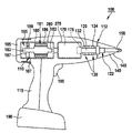
Fig. 1 letter illustrates the electric hand tool according to first embodiment,
Fig. 2 letter illustrates the electric tool according to Fig. 1 of second embodiment.
Embodiment
Fig. 1 illustrates the electric hand tool 100 according to first embodiment.It for example has the tool outer casing 105 that has handle 115, and can mechanically be connected with batteries 190 with electricity ground in order not rely on mains supply.Electric tool 100 examples ground is made up of the storage battery auger machine in Fig. 1.But point out that the present invention is not limited to the storage battery auger machine, but can in different, especially battery-driven electric tool, use, wherein make instrument place rotation, for example for storage battery driver, storage battery percussion drill etc.The present invention can use in the electric tool that electrical network drives equally in addition.
According to an embodiment at least portion's section ground by plastics, for example PC, PA, tool outer casing 105 the insides that ABS and/or PA/ABS process are provided with by batteries drive motors 180 and speed changer 170 190 power supplies, electricity.Drive motors 180 is connected with driving shaft 120 through speed changer 170.Driving shaft 120 can be rotated to support on tool outer casing 105 the insides and is furnished with tool chuck 140 through bearing arrangement 130, and end face 112 positions and example ground that it is arranged on tool outer casing 105 have a drill chuck head 145.For example be fixed on the tool outer casing 105 at this bearing arrangement 130.
Tool chuck 149 is used for receiving tool 150 and can be formed on the driving shaft 120 perhaps being connected with driving shaft to sleeve shaped.Sleeve shaped ground, tool chuck 140 examples ground constitutes and is fixed on the driving shaft through the fixture 122 that is positioned on the driving shaft 120 in Fig. 1.
Constitute with so-called " open frame " structure according to an embodiment drive motors 180.Directly as motor housing, that is, the corresponding stator component of motor 180 and rotor part 181 or 182 can directly support or be fixed on the tool outer casing 105 at the tool outer casing 105 of this electric tool 100.
The drive motors of schematically handling through hand switch 195 180 for example is a direct current machine, and it has commutator 185 and at least in part through parts 186 formations of metal, in Fig. 1, it is not shown at length for view is clear in order to commutate.Commutator 185 has current-collector 183; It sets up sliding contact with two or more brush 187, for example carbon brush on the current-collector rotary surface 189 of subordinate, thus motor 180 is carried the current of electric that are fit to through brushes 187 and current-collector 185 in that electric tool 100 is in service.Can control or regulate drive motors 180 like this at this, not only can realize contrary operation, and can given desired rotating speed.By the operation principle and the structure of the drive motors that is fit to of the known fully commutator that has a subordinate of prior art, save detailed description in order to simplify to describe here.
According to an embodiment be provided with at current-collector 185 positions one be furnished with metal shading ring 110, it is fixed on the tool outer casing 105 and in Fig. 1 and illustrates with analysing and observe.Shading ring 110 preferred shell-like ground constitute and are arranged on circumferential groove 107 the insides that on tool outer casing 105, constitute or are fixed on groove the inside, for example die casting.
Have quadrangle or circular cross section according to an embodiment shading ring 110, and have steel, copper, aluminium, iron, zinc and/or manganese.Therefore shading ring 110 for example can film shape and/or filate ground formation.In addition shading ring 110 can be as stated shell-like and/or portion's section ground helical spring shape ground and/or grill-shaped ground constitute at least.
Fig. 2 illustrates the electric hand tool 100 according to Fig. 1 of second embodiment, and wherein drive motors 180 is different with Fig. 1 constitutes according to so-called " jar " structure.Correspondingly drive motors 180 is arranged on motor housing 280 the insides of subordinate at least.Motor housing 280 is provided with or is fixed on tool outer casing 05 the inside of electric tool 100.
Claims (11)
1. the electric hand tool (100) that has tool outer casing (105); The drive motors (180) of the commutator (185) with subordinate is set therein; It is characterized in that; Upward be provided with the shielding (110) of being furnished with metal at said tool outer casing (105), be used to shield the interference emission of electromagnetism at commutator (185) position.
2. electric tool as claimed in claim 1 is characterized in that, said drive motors (180) is arranged on motor housing (280) the inside of subordinate, and this motor housing is fixed on tool outer casing (105) the inside.
3. according to claim 1 or claim 2 electric tool is characterized in that, being connected of conduction not between the metal parts (186) of said shielding (110) and drive motors (180).
4. like each described electric tool in the above-mentioned claim, it is characterized in that, be arranged on the tool outer casing (105) to said shading ring (110) shell-like.
5. like each described electric tool in the above-mentioned claim; It is characterized in that; Said commutator (185) has current-collector (183); Its brush (187) last at current-collector rotary surface (189) and subordinate is in sliding contact, and wherein said current-collector rotary surface (189) portion's section ground conductively-closed (110) at least surrounds.
6. electric tool as claimed in claim 5 is characterized in that, said at least brush (187) conductively-closed ring (110) surrounds.
7. like each described electric tool in the above-mentioned claim, it is characterized in that said tool outer casing (105) is made of plastics.
8. like each described electric tool in the above-mentioned claim, it is characterized in that said shading ring (110) has steel, copper, aluminium, iron, zinc and/or manganese.
9. like each described electric tool in the above-mentioned claim, it is characterized in that said shading ring (110) has quadrangle or circular cross section.
10. like each described electric tool in the above-mentioned claim, it is characterized in that said shading ring (110) helical spring shape or grill-shaped ground constitute.
11. as each described electric tool in the above-mentioned claim; It is characterized in that; Said shading ring (110) is designed to, and can reduce the interference emission at the electromagnetism of electric tool (100) emission in service at least, and it produces when alternately commutating at commutator (185).
Applications Claiming Priority (3)
| Application Number | Priority Date | Filing Date | Title |
|---|---|---|---|
| DE102010003583A DE102010003583A1 (en) | 2010-04-01 | 2010-04-01 | Hand-held power tool |
| DE102010003583.1 | 2010-04-01 | ||
| PCT/EP2011/055007 WO2011121072A2 (en) | 2010-04-01 | 2011-03-31 | Handheld electric tool |
Publications (1)
| Publication Number | Publication Date |
|---|---|
| CN102812625A true CN102812625A (en) | 2012-12-05 |
Family
ID=44625701
Family Applications (1)
| Application Number | Title | Priority Date | Filing Date |
|---|---|---|---|
| CN2011800169527A Pending CN102812625A (en) | 2010-04-01 | 2011-03-31 | Handheld electric tool |
Country Status (5)
| Country | Link |
|---|---|
| US (1) | US20130106209A1 (en) |
| EP (1) | EP2553794A2 (en) |
| CN (1) | CN102812625A (en) |
| DE (1) | DE102010003583A1 (en) |
| WO (1) | WO2011121072A2 (en) |
Families Citing this family (2)
| Publication number | Priority date | Publication date | Assignee | Title |
|---|---|---|---|---|
| DE102010028299A1 (en) * | 2010-04-28 | 2011-11-03 | Robert Bosch Gmbh | Hand-held power tool |
| GB2586016A (en) | 2019-07-26 | 2021-02-03 | Black & Decker Inc | Electromagnetic Interference suppression |
Citations (3)
| Publication number | Priority date | Publication date | Assignee | Title |
|---|---|---|---|---|
| CN1689763A (en) * | 2004-04-24 | 2005-11-02 | 罗伯特·博世有限公司 | Hand held machine tool with a rotary/impact driving mechanism |
| JP2008221349A (en) * | 2007-03-08 | 2008-09-25 | Matsushita Electric Works Ltd | Power tool |
| CN101656454A (en) * | 2008-06-26 | 2010-02-24 | 创科电动工具科技有限公司 | Power tool including hybrid electric motor design |
Family Cites Families (9)
| Publication number | Priority date | Publication date | Assignee | Title |
|---|---|---|---|---|
| DE3318362A1 (en) * | 1983-05-20 | 1984-11-22 | SWF Auto-Electric GmbH, 7120 Bietigheim-Bissingen | ELECTRIC MOTOR, ESPECIALLY WINDOW WIPER MOTOR |
| US5458159A (en) * | 1993-12-17 | 1995-10-17 | Cooper Industries, Inc. | Shielded electrically powered wire wrap tool |
| DE4439799C1 (en) * | 1994-11-08 | 1996-05-02 | Wolf Gmbh Richard | Electric drive unit for surgical tool |
| US5845718A (en) * | 1997-05-29 | 1998-12-08 | Ingersoll-Rand Company | Resonant oscillating mass-based torquing tool |
| DE19804369C2 (en) * | 1998-02-04 | 2000-02-17 | Bosch Gmbh Robert | Collector motor |
| US7268461B2 (en) * | 2001-02-15 | 2007-09-11 | Integral Technologies, Inc. | Low cost electrical motor components manufactured from conductive loaded resin-based materials |
| DE10248921A1 (en) * | 2002-10-17 | 2004-05-13 | C. & E. Fein Gmbh & Co Kg | Electric tool e.g. edge grinder, with universal motor drive having self-supporting stator with support parts at its ends supporting motor shaft and motor brushes |
| US8508084B2 (en) * | 2008-06-26 | 2013-08-13 | Techtronic Power Tools Technology Limited | Power tool including hybrid electric motor design |
| DE102010028299A1 (en) * | 2010-04-28 | 2011-11-03 | Robert Bosch Gmbh | Hand-held power tool |
-
2010
- 2010-04-01 DE DE102010003583A patent/DE102010003583A1/en not_active Withdrawn
-
2011
- 2011-03-31 CN CN2011800169527A patent/CN102812625A/en active Pending
- 2011-03-31 WO PCT/EP2011/055007 patent/WO2011121072A2/en not_active Ceased
- 2011-03-31 EP EP11712541A patent/EP2553794A2/en not_active Withdrawn
- 2011-03-31 US US13/638,450 patent/US20130106209A1/en not_active Abandoned
Patent Citations (3)
| Publication number | Priority date | Publication date | Assignee | Title |
|---|---|---|---|---|
| CN1689763A (en) * | 2004-04-24 | 2005-11-02 | 罗伯特·博世有限公司 | Hand held machine tool with a rotary/impact driving mechanism |
| JP2008221349A (en) * | 2007-03-08 | 2008-09-25 | Matsushita Electric Works Ltd | Power tool |
| CN101656454A (en) * | 2008-06-26 | 2010-02-24 | 创科电动工具科技有限公司 | Power tool including hybrid electric motor design |
Also Published As
| Publication number | Publication date |
|---|---|
| DE102010003583A1 (en) | 2011-10-06 |
| EP2553794A2 (en) | 2013-02-06 |
| US20130106209A1 (en) | 2013-05-02 |
| WO2011121072A2 (en) | 2011-10-06 |
| WO2011121072A3 (en) | 2012-08-16 |
Similar Documents
| Publication | Publication Date | Title |
|---|---|---|
| EP3015224B1 (en) | Electric screw-fastening tool | |
| EP1430979A1 (en) | A motor and gear box combination | |
| GB2476374A (en) | Inertia system in the drive train of a power hand tool | |
| US9345193B2 (en) | Direct drive electric lawn mower | |
| CN101870097A (en) | Electric screwdriver with magnetic overload protector | |
| CN103201074A (en) | Mechanical impact machine for hand-held machine tools | |
| JP7379461B2 (en) | Hand-held tools, especially impact drivers | |
| JP2017525581A (en) | Handheld machine tool with electronically rectified electric motor as direct drive | |
| EP4113795A2 (en) | Motor rotor with sleeve for retention of magnet ring | |
| JP2006121833A (en) | Electric tool | |
| EP4102687A2 (en) | Overmolded rotor structure | |
| US20250050474A1 (en) | Power tool with coupling mechanism for joining first and second housing portions | |
| JP2024081603A (en) | Handheld tool machine | |
| CN201371408Y (en) | Angle grinder | |
| CN204179910U (en) | A kind of electric tool brushless motor structure | |
| MX2021005817A (en) | Rotary tool. | |
| US20130106209A1 (en) | Handheld electric tool | |
| CN201371283Y (en) | Electric circular saw | |
| CN210756982U (en) | Hand-held angle grinder | |
| US20240204614A1 (en) | Power tool with compact motor and transmission assemblies | |
| US20240022126A1 (en) | Rotor magnet retention structure in brushless motor | |
| CN201371437Y (en) | Electric screwdriver | |
| CN201371260Y (en) | Impact electric drill | |
| JP3078273U (en) | Wheel-type direct drive motor structure for electric vehicles | |
| KR101045780B1 (en) | Power train |
Legal Events
| Date | Code | Title | Description |
|---|---|---|---|
| C06 | Publication | ||
| PB01 | Publication | ||
| C10 | Entry into substantive examination | ||
| SE01 | Entry into force of request for substantive examination | ||
| C02 | Deemed withdrawal of patent application after publication (patent law 2001) | ||
| WD01 | Invention patent application deemed withdrawn after publication |
Application publication date: 20121205 |