CN102829281A - Underwater Hydrocarbon transport pipeline and temperature control device - Google Patents
Underwater Hydrocarbon transport pipeline and temperature control device Download PDFInfo
- Publication number
- CN102829281A CN102829281A CN201210159742XA CN201210159742A CN102829281A CN 102829281 A CN102829281 A CN 102829281A CN 201210159742X A CN201210159742X A CN 201210159742XA CN 201210159742 A CN201210159742 A CN 201210159742A CN 102829281 A CN102829281 A CN 102829281A
- Authority
- CN
- China
- Prior art keywords
- pipeline
- annular space
- regulating system
- conveying equipment
- control
- Prior art date
- Legal status (The legal status is an assumption and is not a legal conclusion. Google has not performed a legal analysis and makes no representation as to the accuracy of the status listed.)
- Granted
Links
- 239000004215 Carbon black (E152) Substances 0.000 title claims abstract description 32
- 229930195733 hydrocarbon Natural products 0.000 title claims abstract description 32
- 150000002430 hydrocarbons Chemical class 0.000 title claims abstract description 32
- 230000001105 regulatory effect Effects 0.000 claims abstract description 76
- 239000012530 fluid Substances 0.000 claims abstract description 39
- 239000007788 liquid Substances 0.000 claims abstract description 26
- 230000001276 controlling effect Effects 0.000 claims abstract description 14
- 238000000605 extraction Methods 0.000 claims abstract description 7
- 239000007789 gas Substances 0.000 claims description 44
- 238000010438 heat treatment Methods 0.000 claims description 22
- 239000011810 insulating material Substances 0.000 claims description 17
- 239000000463 material Substances 0.000 claims description 16
- 238000001816 cooling Methods 0.000 claims description 14
- 239000013307 optical fiber Substances 0.000 claims description 8
- 230000000694 effects Effects 0.000 claims description 7
- 238000004891 communication Methods 0.000 claims description 6
- 230000008859 change Effects 0.000 claims description 5
- 239000000110 cooling liquid Substances 0.000 claims description 5
- 238000013461 design Methods 0.000 claims description 5
- 238000007654 immersion Methods 0.000 claims description 5
- 230000005540 biological transmission Effects 0.000 claims description 4
- 239000001307 helium Substances 0.000 claims description 4
- 229910052734 helium Inorganic materials 0.000 claims description 4
- SWQJXJOGLNCZEY-UHFFFAOYSA-N helium atom Chemical compound [He] SWQJXJOGLNCZEY-UHFFFAOYSA-N 0.000 claims description 4
- 238000007670 refining Methods 0.000 claims description 4
- 229910052724 xenon Inorganic materials 0.000 claims description 3
- FHNFHKCVQCLJFQ-UHFFFAOYSA-N xenon atom Chemical compound [Xe] FHNFHKCVQCLJFQ-UHFFFAOYSA-N 0.000 claims description 3
- 230000000052 comparative effect Effects 0.000 claims description 2
- 238000011900 installation process Methods 0.000 claims description 2
- 230000001681 protective effect Effects 0.000 abstract description 2
- 230000004913 activation Effects 0.000 abstract 2
- XLYOFNOQVPJJNP-UHFFFAOYSA-N water Substances O XLYOFNOQVPJJNP-UHFFFAOYSA-N 0.000 description 20
- 230000033228 biological regulation Effects 0.000 description 13
- 229910000831 Steel Inorganic materials 0.000 description 11
- 239000010959 steel Substances 0.000 description 11
- 238000005485 electric heating Methods 0.000 description 9
- 239000003921 oil Substances 0.000 description 9
- 238000004519 manufacturing process Methods 0.000 description 8
- 238000000034 method Methods 0.000 description 8
- 230000008901 benefit Effects 0.000 description 6
- 230000017525 heat dissipation Effects 0.000 description 5
- 238000005516 engineering process Methods 0.000 description 4
- 230000000670 limiting effect Effects 0.000 description 4
- 230000007246 mechanism Effects 0.000 description 4
- 239000010802 sludge Substances 0.000 description 4
- 239000000243 solution Substances 0.000 description 4
- 238000009434 installation Methods 0.000 description 3
- 239000012212 insulator Substances 0.000 description 3
- 239000002184 metal Substances 0.000 description 3
- 238000012544 monitoring process Methods 0.000 description 3
- 230000005855 radiation Effects 0.000 description 3
- 230000000630 rising effect Effects 0.000 description 3
- 239000013535 sea water Substances 0.000 description 3
- 239000002351 wastewater Substances 0.000 description 3
- IJGRMHOSHXDMSA-UHFFFAOYSA-N Atomic nitrogen Chemical compound N#N IJGRMHOSHXDMSA-UHFFFAOYSA-N 0.000 description 2
- 230000009471 action Effects 0.000 description 2
- 230000015572 biosynthetic process Effects 0.000 description 2
- 230000000740 bleeding effect Effects 0.000 description 2
- 239000004020 conductor Substances 0.000 description 2
- 230000007423 decrease Effects 0.000 description 2
- 238000010586 diagram Methods 0.000 description 2
- 239000000284 extract Substances 0.000 description 2
- 230000006870 function Effects 0.000 description 2
- 238000002347 injection Methods 0.000 description 2
- 239000007924 injection Substances 0.000 description 2
- 230000008569 process Effects 0.000 description 2
- 230000009467 reduction Effects 0.000 description 2
- 238000007789 sealing Methods 0.000 description 2
- 239000007787 solid Substances 0.000 description 2
- 239000000126 substance Substances 0.000 description 2
- 239000000725 suspension Substances 0.000 description 2
- 229910000975 Carbon steel Inorganic materials 0.000 description 1
- MYMOFIZGZYHOMD-UHFFFAOYSA-N Dioxygen Chemical compound O=O MYMOFIZGZYHOMD-UHFFFAOYSA-N 0.000 description 1
- 239000000654 additive Substances 0.000 description 1
- 230000002411 adverse Effects 0.000 description 1
- 239000004964 aerogel Substances 0.000 description 1
- 239000010425 asbestos Substances 0.000 description 1
- 238000000429 assembly Methods 0.000 description 1
- 230000000712 assembly Effects 0.000 description 1
- QVGXLLKOCUKJST-UHFFFAOYSA-N atomic oxygen Chemical compound [O] QVGXLLKOCUKJST-UHFFFAOYSA-N 0.000 description 1
- 230000004888 barrier function Effects 0.000 description 1
- 238000005452 bending Methods 0.000 description 1
- 239000010962 carbon steel Substances 0.000 description 1
- 150000001875 compounds Chemical class 0.000 description 1
- 230000006835 compression Effects 0.000 description 1
- 238000007906 compression Methods 0.000 description 1
- 239000000470 constituent Substances 0.000 description 1
- 238000010276 construction Methods 0.000 description 1
- 230000007812 deficiency Effects 0.000 description 1
- 229910001882 dioxygen Inorganic materials 0.000 description 1
- 238000007667 floating Methods 0.000 description 1
- 239000000446 fuel Substances 0.000 description 1
- 230000008595 infiltration Effects 0.000 description 1
- 238000001764 infiltration Methods 0.000 description 1
- 238000007689 inspection Methods 0.000 description 1
- 238000009413 insulation Methods 0.000 description 1
- 239000012774 insulation material Substances 0.000 description 1
- 230000002045 lasting effect Effects 0.000 description 1
- 230000004807 localization Effects 0.000 description 1
- NMJORVOYSJLJGU-UHFFFAOYSA-N methane clathrate Chemical compound C.C.C.C.O.O.O.O.O.O.O.O.O.O.O.O.O.O.O.O.O.O.O.O.O.O.O NMJORVOYSJLJGU-UHFFFAOYSA-N 0.000 description 1
- 230000004048 modification Effects 0.000 description 1
- 238000012986 modification Methods 0.000 description 1
- -1 nanogel Substances 0.000 description 1
- 229910052757 nitrogen Inorganic materials 0.000 description 1
- 239000003129 oil well Substances 0.000 description 1
- 239000001301 oxygen Substances 0.000 description 1
- 229910052760 oxygen Inorganic materials 0.000 description 1
- 230000036961 partial effect Effects 0.000 description 1
- 239000003208 petroleum Substances 0.000 description 1
- 229920002635 polyurethane Polymers 0.000 description 1
- 239000004814 polyurethane Substances 0.000 description 1
- 238000000197 pyrolysis Methods 0.000 description 1
- 238000011084 recovery Methods 0.000 description 1
- 230000002829 reductive effect Effects 0.000 description 1
- 229910052895 riebeckite Inorganic materials 0.000 description 1
- 229910052710 silicon Inorganic materials 0.000 description 1
- 239000010703 silicon Substances 0.000 description 1
- 238000002791 soaking Methods 0.000 description 1
- 238000005476 soldering Methods 0.000 description 1
- 230000006641 stabilisation Effects 0.000 description 1
- 238000011105 stabilization Methods 0.000 description 1
- 239000007858 starting material Substances 0.000 description 1
- 238000012360 testing method Methods 0.000 description 1
- GWEVSGVZZGPLCZ-UHFFFAOYSA-N titanium dioxide Inorganic materials O=[Ti]=O GWEVSGVZZGPLCZ-UHFFFAOYSA-N 0.000 description 1
Images




Classifications
-
- F—MECHANICAL ENGINEERING; LIGHTING; HEATING; WEAPONS; BLASTING
- F16—ENGINEERING ELEMENTS AND UNITS; GENERAL MEASURES FOR PRODUCING AND MAINTAINING EFFECTIVE FUNCTIONING OF MACHINES OR INSTALLATIONS; THERMAL INSULATION IN GENERAL
- F16L—PIPES; JOINTS OR FITTINGS FOR PIPES; SUPPORTS FOR PIPES, CABLES OR PROTECTIVE TUBING; MEANS FOR THERMAL INSULATION IN GENERAL
- F16L53/00—Heating of pipes or pipe systems; Cooling of pipes or pipe systems
- F16L53/30—Heating of pipes or pipe systems
- F16L53/32—Heating of pipes or pipe systems using hot fluids
-
- E—FIXED CONSTRUCTIONS
- E21—EARTH OR ROCK DRILLING; MINING
- E21B—EARTH OR ROCK DRILLING; OBTAINING OIL, GAS, WATER, SOLUBLE OR MELTABLE MATERIALS OR A SLURRY OF MINERALS FROM WELLS
- E21B36/00—Heating, cooling or insulating arrangements for boreholes or wells, e.g. for use in permafrost zones
- E21B36/003—Insulating arrangements
-
- E—FIXED CONSTRUCTIONS
- E21—EARTH OR ROCK DRILLING; MINING
- E21B—EARTH OR ROCK DRILLING; OBTAINING OIL, GAS, WATER, SOLUBLE OR MELTABLE MATERIALS OR A SLURRY OF MINERALS FROM WELLS
- E21B36/00—Heating, cooling or insulating arrangements for boreholes or wells, e.g. for use in permafrost zones
- E21B36/005—Heater surrounding production tube
-
- F—MECHANICAL ENGINEERING; LIGHTING; HEATING; WEAPONS; BLASTING
- F16—ENGINEERING ELEMENTS AND UNITS; GENERAL MEASURES FOR PRODUCING AND MAINTAINING EFFECTIVE FUNCTIONING OF MACHINES OR INSTALLATIONS; THERMAL INSULATION IN GENERAL
- F16L—PIPES; JOINTS OR FITTINGS FOR PIPES; SUPPORTS FOR PIPES, CABLES OR PROTECTIVE TUBING; MEANS FOR THERMAL INSULATION IN GENERAL
- F16L53/00—Heating of pipes or pipe systems; Cooling of pipes or pipe systems
-
- Y—GENERAL TAGGING OF NEW TECHNOLOGICAL DEVELOPMENTS; GENERAL TAGGING OF CROSS-SECTIONAL TECHNOLOGIES SPANNING OVER SEVERAL SECTIONS OF THE IPC; TECHNICAL SUBJECTS COVERED BY FORMER USPC CROSS-REFERENCE ART COLLECTIONS [XRACs] AND DIGESTS
- Y10—TECHNICAL SUBJECTS COVERED BY FORMER USPC
- Y10T—TECHNICAL SUBJECTS COVERED BY FORMER US CLASSIFICATION
- Y10T137/00—Fluid handling
- Y10T137/6416—With heating or cooling of the system
- Y10T137/6579—Circulating fluid in heat exchange relationship
-
- Y—GENERAL TAGGING OF NEW TECHNOLOGICAL DEVELOPMENTS; GENERAL TAGGING OF CROSS-SECTIONAL TECHNOLOGIES SPANNING OVER SEVERAL SECTIONS OF THE IPC; TECHNICAL SUBJECTS COVERED BY FORMER USPC CROSS-REFERENCE ART COLLECTIONS [XRACs] AND DIGESTS
- Y10—TECHNICAL SUBJECTS COVERED BY FORMER USPC
- Y10T—TECHNICAL SUBJECTS COVERED BY FORMER US CLASSIFICATION
- Y10T137/00—Fluid handling
- Y10T137/6851—With casing, support, protector or static constructional installations
- Y10T137/7036—Jacketed
Landscapes
- Engineering & Computer Science (AREA)
- General Engineering & Computer Science (AREA)
- Mechanical Engineering (AREA)
- Mining & Mineral Resources (AREA)
- Life Sciences & Earth Sciences (AREA)
- Geology (AREA)
- Fluid Mechanics (AREA)
- Environmental & Geological Engineering (AREA)
- Physics & Mathematics (AREA)
- General Life Sciences & Earth Sciences (AREA)
- Geochemistry & Mineralogy (AREA)
- Pipeline Systems (AREA)
- Filling Or Discharging Of Gas Storage Vessels (AREA)
- Production Of Liquid Hydrocarbon Mixture For Refining Petroleum (AREA)
- Heat-Exchange Devices With Radiators And Conduit Assemblies (AREA)
Abstract
The invention relates to a hydrocarbon transport device (1) intended to be immersed and arranged at an extraction wellhead (2), comprising a first pipe (3) through which a first fluid leaving the extraction well (2) flows, the first pipe being arranged in an external protective casing, a piloting system (9, 10, 11, 12, 54) to pilot the temperature in the first pipe controlling an activation element of a regulating system for regulating a heat exchange between the first pipe (3) and the liquid medium filling the immersed external casing, the regulating system comprising at least a second pipe (5) arranged around the first pipe (3) and delimiting an annular space enclosing at least one regulating fluid, this regulating fluid being injected into or expelled from the annular space by the activation element of the regulating system.
Description
Technical field
The present invention relates to the hydrocarbon conveyance conduit technical field of the temperature of can regulate hydrocarbon.
Background technique
Exhausted for preventing middle low temperature (promptly below 120 ℃) offshore oil field, the oil producer can only exploit the submarine oil of deep layer geology storage, for example about 4000 or 6000 meters even depths more.Because heat gradient is 30 ℃ every kilometer fifty-fifty, so the well temperature that goes out of hydrocarbon can be above 150 ℃.Measure the well head place temperature maybe for, for example: 210 ℃ or even 240 ℃.
Therefore, one of them technical barrier is: the device that can adapt to these temperature is provided, bearing the effect of thermal expansion through the mode of resistance to compression or regulation and proof stress, and selects to adapt to the material of these temperature.For example, some mechanical structures like expansion loop, can significantly expand to reduce the bending deflection of hydrocarbon pipeline.Patent application case GB-2188394 discloses another kind of solution, and a kind of helix structure that makes pipe expansion promptly is provided.But for the situation of several meters of every kilometer free expansions of material in the pipeline of long several kilometers or tens kilometers and the pipe, these methods are infeasible economically.
Except the restriction that receives dimensional changes, the metal constituent material of pipeline has maximum yield strength corresponding with maximum allowable stress and that reduce with the rising of temperature.For example, maximum allowable stress can decrease, and under 200 ℃, can reduce 75MPa like carbon steel, and maximum flexibility be about 400 or the Duplex Steel of 450Mpa estimate at ambient temperature to reduce 140MPa.
If thermal expansion is restricted fully, temperature variation increases above 2MPa/ ℃ stress, and according to surveying and determination, high temperature can make pipe thickness significantly increase to resist interior pressure.Suppressing the thermal expansion meeting makes pipeline bear extra power.
Therefore, must reduce the temperature of hydrocarbon conveyance conduit.Cool off even more important to the highest well head of temperature.
Even at the well head downstream part, after the part heat dissipated, temperature maybe be still very high, and further cause technical problem.That is it is the highest, to inject into well the chemical products operating temperature of liquid air-flow.Therefore, for example, anticorrosive product is inoperative under the temperature more than 100 ℃.Electronic component also possibly be damaged or thoroughly be destroyed above under the condition of its Maximum operating temperature.
Thereby, see that from mechanistic angle cooling can not only make equipment work more efficiently, chemical additives or electronic equipment can used near the well outlet port.
A kind of method that adopts sometimes is one section nonisulated pipe to be installed to help cooling in the well outlet port.The length of pipe is no more than tens meters basically, can only carry out 10 to 20 ℃ small size cooling when oil well output is maximum.In addition, end to produce the risk that has nonisulated part formation hydrocarbon obstruction, this scheme is inapplicable to this.In fact, the temperature of waste water can not be reduced to the ambient temperature (being generally 4 ℃) of seawater, because this possibly cause the formation of gas hydrate and other solid, and then stops up the hydrocarbon pipeline.
When another problem is the exploitation oil reservoirs, well head pressure and variation of temperature.During beginning, well head is under the HTHP.This needs significantly cooling when requiring the exploitation beginning, or not even slightly cooling is carried out in exploitation when finishing.
Therefore, need to regulate the temperature in the hydrocarbon conveyance conduit.
In addition, undersea device must satisfy simple in structure, robust requirement.
Summary of the invention
The objective of the invention is to through provide a kind of aim to soak to place refine the well head design, can adapt to the high temperature at production initial stage and can produce the later stage, or produce the hydrocarbon feedway that reduces or lower the temperature when stopping, to overcome the deficiency of existing technology.
For realizing this purpose; The present invention provide a kind of aim to soak place the hydrocarbon conveying equipment that refines the well head design, it comprises first pipeline, flows through said first pipeline; From the first fluid that refines well; Said first piping layout is externally in the containment vessel, and soaks when being loaded on well head full of liquid medium in the containment vessel when the hydrocarbon conveying equipment; Also comprise regulating system; Be used for being controlled at the temperature of the mobile hydrocarbon of first pipeline; At least one starting element in this regulating and controlling system of system, regulating first pipeline and to be full of the heat exchange between the liquid medium of containment vessel, said regulating system comprises that at least one is arranged in second pipeline around first pipeline; Said second pipeline is used to define the annular space that surrounds at least a regulated fluid, and this regulator solution injects or the discharge annular space through the starting element of regulating system.
According to another feature of the present invention, conveyor system comprises the heating system that is used to heat first pipeline, and said heating system is controlled, starts or closed by said regulating system.
According to another feature of the present invention, the startup of regulating system control heating system, and the minimizing of regulating system control heat exchange, promptly from first channel flow to the medium that is full of containment vessel again to the minimizing of the hot-fluid of containment vessel environment.
According to another feature of the present invention, the startup of regulating system control heating system, and the increase of regulating system control heat exchange.
According to another feature of the present invention, feedway comprises: at least one temperature transducer, and wherein said sensor will be sent to regulating system from the temperature signal typical value of refining the fluid that well stream goes out through communication line; The calculator of said regulating system, wherein said calculator at least once compares the signal typical value of receiving and the critical value of record; Said then regulating system is sent the order of heating or cooling according to comparative result.
According to another feature of the present invention, temperature transducer comprises that at least one is arranged at the optical fiber in the annular space, said annular space along first pipeline between first pipeline and second pipeline.
According to another feature of the present invention, insulating material places in the annular space between first pipeline and second pipeline; Said regulated fluid is a gaseous state; Said regulating system comprises gas transmission pipeline, and said pipeline passes to the hole of the enclosed annular space between first pipeline and second pipeline, and gas inspiration or extraction annular space are started by said starting element; The insulating property of insulating material change according to the pressure in the annular space; The variation (between 10mbar and the 1bar) that at least 3 times (between 10mbar and 1bar) reach at least 4 times can take place with W/ (m.K) expression in the thermal conductivity of insulating material.
According to another feature of the present invention, regulating system also comprises the control module of a control supply selector valve in addition, and said supply selector valve is used for selecting the type of injecting gas.
According to another feature of the present invention, the gas supply of the supply line of first gas (like air or xenon) to said starting element carried in selector valve control, or the gas supply of the supply line of second gas (for example helium) to said starting element carried in control.
According to another feature of the present invention, said starting element comprises that one is used for through aspirating vacuum pump; Perhaps said starting element comprises one through the vacuum valve that communicates with vacuum tank.
According to another feature of the present invention, regulating system comprises a control interface that is arranged on the ground service equipment; Also comprise one by control graphical interface remoting and power-actuated immersion type dolly; Said dolly comprises moving positioning device and is furnished with and be connected to the connection element that the enclosed annular space that defines with first pipeline and second pipeline enclosure communicates that said immersion type dolly also is furnished with the positioning element of location outer protection shell.According to another feature of the present invention, the starting element of said regulating system is embedded in the dolly, and this dolly comprises the gas tank that at least one communicates with connecting element through said starting element.
According to another feature of the present invention, regulating system comprises a control interface that is arranged on the ground service equipment; Also comprise a flush bonding module that is incorporated into the end structure at feedway outlet/inlet place; Said flush bonding module is by the control graphical interface remoting and need energy supply; And said merge module comprises that one is connected on the connection element that the enclosed annular space that defines with first pipeline and second pipeline enclosure communicates; And be furnished with the said starting element of regulating system, comprise the gas tank that at least one communicates with connecting element through said starting element.
According to another feature of the present invention, said starting element is a pump, and regulated fluid exists with the form of cooling liquid, and this cooling liquid flows in annular space under the effect of suction pump, and flow to exit orifice from inlet hole and flow to the medium that is full of the outer protection shell again.
According to another feature of the present invention, said regulating system comprises a closed-loop path, and said closed-loop path is passed the inner pipeline of containment vessel by at least one and constituted, and said exit orifice communicates with inlet hole through said at least one pipeline.
According to another feature of the present invention, said regulating system comprises the thermoinsulation material that is arranged on around second pipeline.
According to another feature of the present invention; Said feedway comprises the 3rd pipeline; Said the 3rd pipeline is arranged at around second pipeline and certain distance is arranged with it, forms another annular space, and said thermoinsulation material places said annular space; Regulating system is controlled the pressure in the annular space between second pipeline and the 3rd pipeline through the gas that sucks or discharge this enclosed annular space, and said annular space is provided with a through hole mutually that communicates with the device that injects (discharge) gas.
According to another feature of the present invention, said feedway is installed by land, forms one several kilometers long single builtup member, is convenient in installation process, before by submergence, it is dragged in the sea.This builtup member also is called " tying ".
First advantage of the present invention is that said hydrocarbon feedway can significantly reduce wastewater temperature, promptly can reduce by 30,50 or 100 ℃, and therefore, this device can be installed in well head and be designed between the delivering cryogenic fluid conventional pipelines.
Another advantage of the present invention is that about 1MW can dissipate through simple and easy firm device to the high heat energy of 50MW.
Another advantage of the present invention is producing the downtime, places the hydrocarbon feedway of well head can remain on to make and produces under the temperature that restarts.
Another advantage of the present invention is that the feedway that is positioned at the well outlet constitutes a radiation system, especially can effectively keep out any dirt of exchange surface, because it has utilized the large size pipeline to carry out heat exchange.With single builtup member form process feedway, be called " tying ", can be dragged in the sea during installation, be several kilometers (being generally 8 kilometers), even tens kilometers.
Description of drawings
Below in conjunction with accompanying drawing and specific embodiment the present invention is further specified.
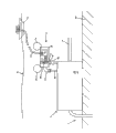
Fig. 1 is the schematic representation that feedway of the present invention is connected with well and is connected with manufacturing mechanism.
Fig. 2 is the schematic representation that well capacity descends in the petroleum reservoir recovery process.
Fig. 3 is the sectional view of feedway of the present invention.
Fig. 4 is the profile diagram of feedway of the present invention.
Fig. 5 is the schematic representation of humidity control system.
Fig. 6 is thermoregulator control schematic representation.
Fig. 7 and Fig. 8 are the schematic layout patterns of humidity control system control unit.
Fig. 9 is the schematic representation of the remote operated vehicle that is used for according to temperature to be controlled gas pressure in the annular space being controlled.
Figure 10 and Figure 11 are each profile diagrams of feedway embodiment of the present invention.
Figure 12 is through the temperature curve schematic representation of the waste water of certain liquid cooling in the conventional pipelines.
Figure 13, Figure 14 and Figure 15 are the various variant embodiment of feedway of the present invention.
Embodiment
Fig. 1 has showed that is arranged in an immersion type hydrocarbon feedway that refines well head 2.Represent very dark hydrocarbon pond with a pouch 28 among the figure, on the hydrocarbon pond, open an inlet with drill bit 29.Drill bit 29 links to each other with well head 2 under water.The hydrocarbon pond is positioned at 4000 to 8000 meters or more depths (P50).Well outlet conduit 83 is connected to feedway 1 with drill bit 29.This pipeline 83 is a conventional pipelines, and itself can not cause significantly temperature variation.
Pipe-in-pipe is arranged in the outer protection shell 4.As shown in Figure 1, element shown 6 relative second pipelines 5 are fixed protecting sheathing 4.Fixed element 6 comprises, for example, pad and eyelet, or other are fastening or hook element are used to make each element to be assembled in corresponding position separately.Opening 18 is set on the outer protection shell 4, when outer protection shell 4 soaks the final position that places the well outlet, can be full of medium like this.
During practice feedway 1 of the present invention, should it be installed in the land, drag with ship then, like this under the control of the buoyancy that said shell 4 internal capacities provide, device 1 bubbles through the water column 52 or under water, is full of air or nitrogen in the said shell 4.When desiring to be installed on the device 1 arrival mounting point of well head 2, water can be filled with outer protection shell 4, makes device 1 submergence.Carry out water filling through opening opening 18, can feedway 1 be arranged on said well head 2 positions then, and lie against on the sea bed 53.
It is unlimited that opening 18 can keep, and allows water in shell, freely to circulate, and also can close, and this moment, water can not circulate, and heat exchange still can be carried out with its ambient, external environment in containment vessel 4 inside simultaneously.Outside containment vessel 4 is not adiabatic.Containment vessel 4 for example is made of metal, can natural heat conduction.
The annular space 7 that is made up of first pipeline 3 and second pipeline 5 seals, and communicates with hole 8, to inject or discharge fluid, for example gas.Therefore, the air pressure in the annular space 7 can raise or reduce.The temperature regulation fluid that is injected into or discharges annular space is gas (as previously mentioned) or liquid (will be described hereinafter).
Regulating system increases or reduces by first pipeline 3 and be full of the heat exchange of 61 in the medium of outer protection shell, and said medium does, for example, and seawater.
Suck or discharge the humidity control system control of going up and down by control annular space 7 internal air pressures.Said humidity control system also can be with the pressure control in the annular space 7 in predetermined value.
Said humidity control system is controlled the starting element of said regulating system, and said starting element does, for example, and pump 10, and comprise electrical module 11 and electronic control module 12.Said pump by, for example, power module 11 control.Power module 11 receives the instruction of electronic control module 12.Said electronic control module 12 by, for example, administration module 54 control, said module will specify hereinafter.
The starting element of said regulating system can be pump or valve, will be described hereinafter.
Use is furnished with the pump 10 of heat engine or electric motor.
The starting element of said regulating system also can manually be controlled.
Said humidity control system comprises pressure transducer 78, according to this sensor the air pressure of regulating in the annular space 7 is regulated.Said pressure transducer 78 for example, can be incorporated in the pump or is arranged in the steam line of feedway 1 of the present invention.
Can select for use according to the volume of annular space 7 to suck with certain aspiration or the suction pump 10 of gas bleeding, said gas is injected into annular space 7 or therefrom discharges.In this case, for reaching maximum emission or maximum aspiration amount, open or close suction pump 10 according to the temperature of measuring.Operator also can set different suctions or emission level.Low pressure can be made as, and for example, 48mbar even 2mbar, high pressure are made as 1bar even 100bar.Can be provided with automatically or manually be provided with.
The starting element of said regulating system also can be set to automatic control.
Along with the rising that the pipe-in-pipe heat dissipates to the outside of the inside of containment vessel 4 and containment vessel 4, air pressure raises in the annular space 7.Along with the reduction of the pipe-in-pipe heat dissipation of the inside that is positioned at containment vessel 4, air pressure also decreases in the annular space 7.
Therefore, can regulate the dissipation of heat as required.Come the heat of the fluid of artesian well to depend on the degree of depth P50 of oil reservoirs.Usually, the temperature in the oil reservoirs raises about 30 ℃ for every kilometer.
The predetermined length that is positioned at the hydrocarbon feedway 1 of well head 2 is L51.This length L 51 has determined its cooling capacity to a certain extent.The length L 51 of hydrocarbon feedway 1 does, for example, and 0.5km to 20km.
When said humidity control system was made as maximum with the heat dissipation capability, sufficiently long length can realize that maximum heat dissipates, thereby can cool off the fluid that from well 2, extracts as far as possible.
Insulating material 17 for example, is arranged in the annular space 7, will combine Fig. 3 to explain hereinafter.The material that should select insulating capacity can change according to the air pressure in the annular space 7.This material does, for example, and poromerics.
As shown in Figure 1, said annular space also can be empty.
Annular space 7 also can be filled with the material or the open-cell polyurethane of aerogel, nanogel, asbestos, the sale of
 brand or be applicable to other any material or the open-cell material compound of maximum temperature.When said temperature regulation fluid was gas, the insulating capacity of selected materials should be able to be made maximum change according to the variation in pressure of allowing in the annular space, for example, when pressure when 10mbr fades to 100bar, heat conductivity variation ratio should be 1/10, even is 1/30.
From the fluid of underground extraction, through behind the feedway 1 of the present invention, carry by the pipeline 14 that is positioned on the sea bed, be delivered to manufacturing mechanism 16 by pipeline 38 again.Pipeline 14 can be conventional pipelines, and this pipeline need not meet the production requirement to " must be high temperature resistant " pipeline regulation.Pipeline 14 length on the sea bed do, for example, and tens kilometers.Process is arranged in the fluid 1 of the device 1 at well head 2 places, also can directly be delivered to manufacturing mechanism 16. by pipeline 38
The temperature regulation fluid that injects feedway 1 annular space also can be stored in the end structure 112 or 113 storage tank of feedway 1 through suction pump, and at this moment, suction pump also will be installed in end structure 112 or 113.
The pipeline 14 of device 1 according to the invention and the downstream of pipeline 38 can for example be designed to any kind according to installation requirement, the pipeline of single tube or pipe-in-pipe, spring tube or other type.
When Fig. 2 is abandoned wells, the function schematic representation that the pressure and temperature of the hydrocarbon of extraction reduces along with exploitation time E49.Therefore, heat radiation Q48 needs have in various degree just been produced.After exploiting 2 years E49, the heat dissipating capacity Q48 that needs reduces, and is for example, half the.The hydrocarbon temperature is high more, and for example, the heat dissipating capacity Q48 of requirement is big more.Under the uniform temp, hydrocarbon pressure is big more, and for example, the heat Q48 of requirement is also big more.
Therefore, if exploitation suspends a period of time of regulation, need and need heat dissipating capacity be minimized (through reducing the air pressure of annular space 7) when production is stopped work through heating and come holding temperature.
When production restarted, heating for example, stopped, and heat dissipation increases, for example, and through the air pressure of rising annular space.
Thereby possibly need cooling or heating.
As shown in Figure 3, temperature transducer 19 is arranged in the annular space.Temperature transducer 19 comprises, for example, and the optical fiber of arranging along first pipeline 3.Said annular space is filled up by the same with it solid insulating material 17 of shape.The outer cover of sensor 19 is positioned at, and for example, fills up in the insulating material 17 of annular space.Said annular space also comprises insulated heating wire 55, and insulated heating wire 55 heads on first pipeline 3.Said humidity control system is included as the control module of electric heating wire 55 power supplies.For example, in insulating material 17, leave the space that insulated heating wire 55 is installed.
The pliability of the insulating material that provides should be able to be enough to electric wire and optical fiber are embedded in the said insulating material.
Be illustrated in figure 3 as, with not limiting mode, the pipeline of setting up in the outer protection shell 4 or cable 56.The pipeline that these are set up or cable 56 can promising those skilled in the art know various functions, be installed in the different hydraulic element and the battery of each element in feedway 1 inlet's end structure 112 with control.The advantage of outer protection shell 4 is that the various addition items with equipment take on the ship.
Supporting member 6 is radial arrangement, and pipe-in-pipe is positioned at the center of outer protection shell 4.Water fills up less than space 61 what link to each other with pipe-in-pipe in the outer protection shell 4, makes heat from pipe-in-pipe, even from the pipeline of three ring walls, conducts with a kind of controlled, easy modeled mode.This advantage will specify hereinafter.The pipeline instance of three ring walls will be described hereinafter.
As shown in Figure 3, the movable element 57 of sea bed 53 lies in the both sides of outer protection shell 4.Advantageously, the diameter long enough of outer protection shell 4 need not trench digging.Its diameter is that for example, 100 arrive 200cm.Although may produce sludge 57 and dirt on the both sides of containment vessel 4, outer protection shell 4 these length of confirming also can be kept enough big heat exchange surface.
Opposite with the device under the existing technology, therefore feedway of the present invention can bear inside and outside sedimentary influence because himself length is longer.
According to existing technology, very responsive to inner or outside sludge to the localization method of the nonisulated pipeline in few partial wells outlet port, sludge has greatly limited location efficiency, and therefore, when carrying out heat exchange, this method has very big uncertainty.In addition, because this solution works with the go-no-go mode, therefore can not adapt to any change of fluid in the pipeline.
According to existing technology, if to the pipeline trench digging, then heat exchange can not accurately be regulated.
In the present invention, outer protection shell 4 than major diameter, for example, 100cm, total energy is through environments such as subsea maintaining heat exchange surface.Therefore, pipe-in-pipe environment and heat exchange characteristics thereof are confirmed, because the geometrical construction around the pipe-in-pipe is in check.Estimate that through calculating that heat exchange is carried out people can confirm that pipe diameter is the present invention's structure of 100cm, externally containment vessel 4 internal-external temperature differences are to obtain the above heat dissipation rate of 1kW/m under 10 ℃ the situation.This several kilometers long feedway thereby can dissipate hundreds of myriawatt heat.
For example, determining dimensions is carried out according to the heat exchange amount in the outer protection shell 4.
Fig. 4 is device 1 embodiment's a sectional view, comprises the optical fiber of arranging along first pipeline 3 19.Electric heating wire 55, for example, also along first piping layout.Therefore, can it be heated along the total length of first pipeline 3.Insulating material 17 fills up annular space.Therefore, the temperature of first pipeline, 3 assemblies can be controlled.
Shown is the longitudinal plane of outer protection shell 4.Do not demonstrate the steel plate 58A at containment vessel 4 two ends and the soldering point of 58B.
Pipe-in-pipe is inserted in the outer protection shell 4, uses terminal steel plate 58A and 58B to close containment vessel 4 then in addition.The circular cross-section of outer protection shell 4 for example, is the center with the pipe-in-pipe.Can be behind the water during the ship that the opening 18 of outer protection shell 4 makes feedway 1 exported 2 tops by well is pulled into by submergence.The space that do not occupied in the outer protection shell 4 then 61 is filled up by water.
The pipeline 59 that is arranged among the first steel plate 58B communicates with the pipeline 83 in well 2 outlet ports.This pipeline 59 with, for example, the connecting element 60 in well outlet port communicates.The end structure 112 of inlet can, for example, arrange connecting element.
The inside of first pipeline 3 with, for example, the pipeline 79 that is arranged among the second steel plate 58A communicates, steel plate 58A links to each other with outlet conduit 14.For example, in the end structure 113 in feedway 1 outlet port connecting element and installation elements are set.
The pipeline 62 that is arranged among the second steel plate 58A communicates with annular space 7 through hole 8.Pipeline 62 is radial and opens wide to outside containment vessel 4.The connecting element 63 of feedway 1 outer installment pipeline 62.
For example, suction pump 10, power supply 41 and gas tank 31 are arranged in the end structure 113 in outlet port.The gas tank 31 that communicates with suction pump 10 through pipeline 33 for example, is full of it or finds time air injection ring shape space 7 with it through suction.Suction pump 10 is controlled by executive component 11 automatically, and element itself is by electronic interface 12 controls.Administration module 54 for example, is sent to interface 12 to control signal according to the computer recording program of being carried out by this module.Suction pump 10 links to each other with connecting element 115, and connecting element 115 links to each other with connecting element 63, and connecting element 63 links to each other with annular space 7.
For clarity sake, not demonstrating other that communicate with administration module 54 is connected.
Passage 64 by element 65 sealings is parallel with the longitudinal axis of device 1, so that be connected with optical fiber 19.The connecting element 65 that links to each other with optical fiber 19 is positioned at the outer surface of steel plate 58A, and is arranged in, for example, and in the end structure 113.
Can arrange other pipeline so that introduce other control or test mode.Other embodiment who is positioned at the feedway 1 at well head place will be described hereinafter.
Fig. 5 is the detailed maps of said regulating system, and temperature transducer 19 is sent to management system 54 through the temperature signal typical value that communication line 20 and connecting element 65 will leave the fluid of well 2 among the figure.
Signal and program recorded data adjustment module 12,84,37 and 86 according to sensor 19 transmission. Critical value 43,44,45 is stored in, and for example, with calculator 21, for example, this computer is done contrast to value and the critical value obtained in the storage.
Fig. 6 is the example schematic that control is simplified in heat radiation/heating.When temperature is higher than when confirming temperature 45, maximum radiating control 46 starts.Be lower than definite temperature 44 if measure temperature, then minimum heat control starts.Because critical temperature 44 subcritical temperature 45 are so will assign the temperature hysteresis control command.Also shown definite temperature 43, promptly be lower than temperature 44, be lower than this temperature heating control device 68 and trigger.
This controlling schemes that operates based on the go-no-go mode also can be undertaken and carried out by calculator 21 by the program in the storage 22 of being stored in.Yet, develop more complicated control program step by step as required.Dispel the heat or add heat control and can carry out by feedback loop.
Fig. 7 showed around the regulating system starting element layout and, for example, be suction valve, suction valve provides an outlet conduit that is connected to valve 35, this valve is used to close or opening conduits 9, this pipeline 9 is connected to the hole 8 that communicates with annular space 7.When valve 35 was closed, the gas pressure in the annular space remained unchanged; When valve 35 was opened, air pressure raise under the effect of pump 10 or reduces.Advantageously, through cut-off valve 35, need not the air pressure that extra energy comes the holding temperature adjustments of gas.Valve 35 is during with annular space 7 hermetically closings, and the suction pump 10 of exerting pressure to annular space in fact is cut off.
The final controlling element 36 that controlled module 37 is regulated places disconnection or operating position module 37 to receive control signals through input (going out) port 25 cut-off valve 35.Often those skilled in the art will recognize that to increase valve and control unit to guarantee high as far as possible reliability and to prevent unexpected infiltration for undersea device.For clarity sake, this equipment complex does not show in the accompanying drawings.
For example, when starting aspiration procedure when reducing the air pressure of annular space, said suction pump also with discharge pipeline 70 and link to each other.To be discharged in the air or under water, for example, under the situation of using remote operated vehicle.Also can be discharged in the special case that for this reason is equipped with.
Discharge pipeline and suction channel and also can be designed to open-air formula in future.
With limiting mode not, gas tank 31 and 32, Executive Module 11, final controlling element 85 and 36 can place on surface platform or the service ships, also can be arranged in and tie up end structure 112 and 113.Service ships can be the ship on the water surface, also can be can be under water movable ship, for example telecar also is called ROV (remote-controlled vehicle).ROV will be further elucidated hereinbelow.
Control air pressure in the annular space 7 (segment space filling poromerics); For example; When the gas that injects is air, make thermal conductivity 3 with the initial value (when pressure is 10mbar) of 10mW/ (m.K) with can reach variation between the high value (when pressure is 60bar) of 80mW/ (m.K); And the some of the heat energy through heat insulator in the heat exchange between the environment (heat flow) the representation unit time is directly proportional with the temperature difference between high temperature side and low temperature side, is inversely proportional to the thickness of insulator.
When insulator when compressing the microporous insulation material that forms by pyrolysis silicon and rutile particulate, with the helium replaces air can make thermal conductivity at 6 to 20mW/ (m.K) (when pressure is 10mbar) to 150 to 200mW/ (m.K) (when pressure is 60bar).This material is produced by Microtherm company, and trade mark is

As shown in Figure 8, the heating process of electric heating wire 55 by, for example, control module 86 control, this module comprises Executive Module 39, the electric heating wire 55 in the annulus 7 is through its electric power connection of conductor cable 40 usefulness.Conductor cable 40 is connected element 67 for the part that links to each other with electric heating wire 55 provides.Executive Module 39 for example, receives electric energy through power supply 41.
Fig. 9 is the schematic representation of remote operation soaking type dolly 71, and this dolly is through regulating the air pressure control heat dissipation of annulus 7.The water surface safeguards that ship 72 comprises interface 26 and 27, and with control remote operation dolly 71, this ship itself also comprises control interface 24.Under the situation of ways to restrain not, remote operation ship 71 can be self-powered or be safeguarded ship 72 power supplies by the water surface.Communication line is safeguarded between ship 72 and the remote operation dolly 71 at the water surface, but also can be used the electromagnetic communication mode.
For simplifying accompanying drawing, only show a compressed oxygen gas tank 31 that suction pump 10 is provided.For simplifying accompanying drawing, different sensors (for example pressure transducer) and some final controlling element are not shown.
Remote-operated dolly 71 comprises the hook and the positioning element 77 in outstanding cabin 76.Hook positioning element 77 aims at and hooks outer protection shell 4 and design.Carry out the hook action through being arranged in the suspension hook 82 of confirming the position, correctly to be remote operation dolly 71 location.Suspension hook 82 also can link to each other remote operation dolly 71 with the feedway that is arranged in well head 1.
Link to each other with the element that is communicated in annular space 7 63 in case be used to connect the connection element 75 of annular space, gas can be sucked under the effect of suction pump 10 or extract out by bleeder hole 8.Being connected and breaking off all and under air-proof condition, carrying out of the connection element 75 that is used to connect annular space and the element that is communicated in annular space 7 63.Also can connect with element 63 that annular space 7 communicates before, pressurize for the blowdown piping 9 of said pump.The locking/final controlling element of unblanking by administration module 54 controls can integratedly be arranged at the connection element 75 that is used to connect annular space, connects or off action to carry out.
Combine Figure 10,11,12,13 and 14 pairs of variant embodiment to do and specify now, among the figure, the regulated fluid in the annular space 7 between first pipeline 3 and second pipeline 5 is a liquid.End at annular space injects liquid, in the operation that liquid was discharged or extracted out to the other end, helps to make the circular flow of temperature control liquid, and liquid can be taken away the additional heat that need dissipate like this.
Figure 10 is the embodiment's schematic representation that is arranged in the feedway 1 of well head, and wherein the annular space 7 between first pipeline 3 and second pipeline 5 comprises temperature control liquid.This liquid possibly flow, and increases by first pipeline 3 and is full of the heat exchange between the medium 61 of outer protection shell 4 with the mode through the transmission heat that flows.Be used for controlling the mobile of annular space 7 temperature regulation fluids or stopping by being arranged in the suction pump of controlling at containment vessel 4 outside control interfaces 101 100.Suction pump 100 is installed on, for example, and in the end structure 112.
Like Figure 10, shown in 11 and 14, the temperature regulation fluid circulates in the closed-loop path.
The closed-loop path that is used for the temperature regulation circulation of fluid comprises, for example, and the metallic conduit 109 of the medium 61 through being full of outer protection shell 4.Pipeline 109 links to each other with the pipeline that is connected annular space 7 127 through external pipe 128.Pipeline 109 also links to each other with the pipeline that is used to make the regulated fluid circuit be connected suction pump 100 103.
The suction pump 100 that is started by interface 101 can make regulated fluid in the closed-loop path, circulate.By the suction pump 100 that interface 101 is closed, can be used for making regulated fluid to stop circulation.
The temperature regulation fluid is cooled when passing through the pipeline 109 that is used to carry the medium 61 that is full of containment vessel 4.
For example, when getting into annular space 7 with pipeline 128 that the pipeline that is connected in suction pump 100 109 is connected, said fluid also can be heated, and is shown in figure 10.Heating process can be carried out by the coil 106 that is wrapped on the pipeline 128.Source element 107 heating that coil 106 is controlled by interface element 108 promptly are provided with an expansion tank 114 that is connected in temperature control liquid loop.Therefore, starting said pump can cool off, and perhaps, said pump can combine with heating element independently.
Shown in figure 11, electric heating wire 55 also maybe be along 5 configurations of second pipeline.In this case, an expansion tank 114 that is connected in temperature control liquid loop also is set.
Insulating material 17 can be fixed on around second pipeline 5 by metal tape or protective film 116, and this embodiment is shown in figure 14.
Insulating material also can place the 3rd pipeline 110 around second pipeline 5, to form annular space 111.Shown in figure 11, the air pressure in second annular space 111 is controlled to increase or to reduce by second pipeline and be full of the heat exchange between the medium 61 of outer protection shell 4.This pressure control as previously mentioned, is carried out through the pipeline 88 that communicates with second annular space 111.The connection element 89 of second annular space 111 is arranged in the outside of outer protection shell 4.
In the variant embodiment in Figure 10, also pipeline 109 can not be set.This embodiment is shown in figure 13, and liquid is through annular space 7, and the space 61 through outer protection shell 4 returns annular space 7 then, in this way circulation.In this modification, breach 18 possibilities for example, are closed after medium 61 is full of seawater.
The circulation of temperature control liquid has improved rate of heat exchange, and the circulation that stops this liquid has improved adiabaticity.
Figure 12 is a liquid cooling tube effluent temperature curve schematic representation, with the effect of explanation following current or adverse current cooling.
Under the situation of limiting mode not, like Figure 10,11, shown in 13 and 14, circulating of liquid of temperature control is following current.Temperature control liquid is following current or circulated in countercurrent as required.
Shown in figure 12, the circuit of pipeline following current below 1000 meters water temperature 117 is lower than oil temperature 118, and in the whole residue length of feedway 1, keeps the progressively temperature of reduction.
The water temperature 119 of the circulated in countercurrent that pipeline is last 1000 meters is lower than oil temperature 120.But, water temperature will soon adapt to the temperature value corresponding to the oil temperature of well outlet.
Shown in figure 12, the length of 6000m is not limited altogether, and this is used to explain that the cooling liquid of utilizing following current or circulated in countercurrent is got off the temperature stabilization of cooling circuit.
As required, the present invention can adopt any circulating direction of temperature control liquid.
Among the present invention, heat can be preferably leaves along second pipeline 5 of feedway 1, by heat eliminating medium 61, but chilling temperature control liquid.
Another variant embodiment is described now.Shown in figure 15, aim to soak and place the hydrocarbon conveyance conduit 1 that refines well head 2 designs to comprise, as previously mentioned, first pipeline 3 is from the first fluid flow therein of refining well 2.Device 1 soaks when being loaded on well head, and outer protection shell 4 full of liquid media, said first piping layout are externally in the containment vessel 4.Said regulating system comprises second pipeline 5 that is arranged in around first pipeline 3 and defines the annular space 7 that surrounds temperature regulation fluid and insulating material 17.Under the different annular space pressures, the insulating property of insulating material 17 are different.In this embodiment, the starting element of said humidity control system is a valve 123, and said temperature regulation fluid is a gas.The gas of injection or extraction annular space 7 depends on the position of said regulating system starter gate valve 123.
The said first ducted hydrocarbon humidity control system comprises supercharging oxygen tank 121 and vacuum tank 122.Can reach vacuum state through the mode of bleeding.The volume of jar 122 will be confirmed, be vacuum state in the volume.Through vacuum tank 122 is communicated with annular space 7, gas can be extracted out from annular space 7 like this.
Starting element 123 is valves that are arranged in diverse location, comprise that vacuum tank 122 communicates with annular space 7 the position, the position that position that annular space 7 communicates with supercharging gas tank 121 and annular space 7 are closed.Under the situation of limiting mode not, can use air but not other gas valve 123 is connected on the connection element 63 that links to each other with annular space 7 by connecting element 126.
Heat exchange efficiency along pipeline 3 can make the thermal equilibrium between said regulated fluid and the hydrocarbon feedway 1 back is being installed lasting several kilometers at most of primary importances.Effectively solution is that longer feedway 1 can be installed, the problem of interior (outward) the portion dirt that (outward) portion sludge produces in solving through the heat exchange of carrying out farther distance.
To one skilled in the art, the present invention also can adopt various embodiment.Therefore, existing embodiment only can be considered the example description of the present invention to the appended claims regulation.
Claims (18)
1. one kind aims to soak and places the hydrocarbon conveying equipment (1) that refines well head (2) design; Comprise first pipeline (3) that is arranged in the outer protection shell, flow through said first pipeline, from the first fluid that refines well; And when the hydrocarbon conveying equipment soaks when being loaded on well head, full of liquid medium in the containment vessel; The regulating system that also comprises the temperature that is used for being controlled at the hydrocarbon that first pipeline flows; At least one starting element in this regulating and controlling system of system is to regulate first pipeline and to be full of the heat exchange between the liquid medium of containment vessel; Said regulating system comprises that at least one is arranged in first pipeline, second pipeline on every side; Said second pipeline is used to define the annular space that surrounds at least a regulated fluid, and this regulator solution injects or the discharge annular space through the starting element of regulating system.
2. conveying equipment according to claim 1 (1) further comprises the heating system that is used to heat first pipeline (3), and said heating system is controlled, starts or closed by regulating system.
3. conveying equipment according to claim 2 (1) is characterized in that, the startup of said regulating system control heating system, and the minimizing of regulating system control heat exchange.
4. according to claim 2 or 3 described conveying equipments (1), it is characterized in that said regulating system is controlled closing of heating system, and the increase of regulating system control heat exchange.
5. according to the described conveying equipment of claim 2 to 4 (1); Further comprise at least one temperature transducer, wherein said sensor will be sent to regulating system (9,10,11,12,54) from the temperature signal typical value of refining the fluid that well stream goes out through communication line; The calculator of said regulating system, wherein said calculator at least once compares the critical value (44,45) of signal typical value of receiving and record; Said then regulating system is sent the order of heating or cooling according to comparative result.
6. conveying equipment according to claim 5 is characterized in that, temperature transducer (19) comprises that at least one is arranged in the optical fiber in the annular space (7), and said annular space is defined between first pipeline and second pipeline and reaches along first pipeline (3).
7. according to the described conveying equipment of above arbitrary claim, insulating material (17) places in the annular space between first pipeline (3) and second pipeline (5); Said regulated fluid is a gaseous state; Said regulating system comprises gas transmission pipeline, and said pipeline passes to the hole of the enclosed annular space between first pipeline and second pipeline, and gas inspiration or extraction annular space (7) are started by said starting element; The insulating property of insulating material (17) change according to the pressure in the annular space; The variation (between 10mbar and the 1bar) that at least 3 times (between 10mbar and 1bar) reach at least 4 times can take place with W/ (m.K) expression in the thermal conductivity of insulating material.
8. conveying equipment according to claim 7 (1) is characterized in that, said regulating system also comprises the control module (84,85) of a control supply selector valve in addition, and said supply selector valve is used for selecting the type of injecting gas.
9. conveying equipment according to claim 8 (1); It is characterized in that; The gas supply of the supply line (33) of first gas (like air or xenon) to said starting element carried in selector valve (30) control, or the gas supply of second supply line (34) of second gas (for example helium) to said starting element carried in control.
10. according to the described conveying equipment of above arbitrary claim (1), it is characterized in that said starting element comprises that one is used for through aspirating vacuum pump; Perhaps said starting element comprises one through the vacuum valve that communicates with vacuum tank (123).
11., it is characterized in that regulating system comprises a control interface (26,27) that is arranged on the ground service equipment (72) according to the described conveying equipment of above arbitrary claim (1); Also comprise one by control interface (26,27) remote control and power-actuated immersion type dolly (71); Said dolly comprises moving positioning device and is furnished with the connecting element (71) that is connected to the connection element (75) that the enclosed annular space that defines with first pipeline and second pipeline enclosure communicates that said immersion type dolly (71) also is furnished with the positioning element (77) of location outer protection shell (4).
12. conveying equipment according to claim 11, the starting element of said regulating system is embedded in the dolly, and this dolly comprises that at least one passes through the gas tank (31) that said starting element communicates with connecting element (75).
13., it is characterized in that regulating system comprises a control interface (26,27) that is arranged on the ground service equipment (72) according to the described conveying equipment of claim 1 to 10; Also comprise a flush bonding module that is incorporated into the end structure (112,113) at feedway outlet/inlet place; Said flush bonding module can and need energy supply by control interface (26,27) remote control; And said merge module comprise one be connected to first pipeline and second pipeline (3,5) between connecting element (75) on the connection element that communicates of the enclosed annular space that defines; And be furnished with the said starting element of regulating system, comprise at least one gas tank that communicates with connecting element through said starting element (31).
14. according to one of them described conveying equipment of claim 1 to 6; Said starting element is a pump; Regulated fluid exists with the form of cooling liquid; This cooling liquid is flowing in annular space (7) under the effect of suction pump, and flow to exit orifice from inlet hole and flow to the medium that is full of outer protection shell (4) again.
15. conveying equipment according to claim 14 (1); It is characterized in that; Said regulating system comprises a closed-loop path, and said closed-loop path is passed the inner pipeline (109) of outer protection shell (4) by at least one and constituted, and said exit orifice communicates with inlet hole through said at least one pipeline.
16., it is characterized in that regulating system comprises the thermoinsulation material (17) that is arranged in around second pipeline according to claim 14 or 15 described conveying equipments (1).
17. conveying equipment according to claim 16 (1); It is characterized in that; Further comprise the 3rd pipeline (110); Said the 3rd piping layout is around second pipeline and certain distance is arranged with it, forms another annular space (111), and said thermoinsulation material (17) places said annular space; Regulating system is controlled the pressure in the annular space (111) between second pipeline and the 3rd pipeline through the gas that sucks or discharge this enclosed annular space, and said annular space (111) is provided with a through hole mutually that communicates with the device that injects (discharge) gas.
18., it is characterized in that feedway (1) is installed by land according to the described conveying equipment of above arbitrary claim (1), form one several kilometers long single builtup member, be convenient in installation process, before by submergence, it is dragged in the sea.
Applications Claiming Priority (2)
| Application Number | Priority Date | Filing Date | Title |
|---|---|---|---|
| FR11.01577 | 2011-05-23 | ||
| FR1101577A FR2975748B1 (en) | 2011-05-23 | 2011-05-23 | UNDERWATER DEVICE FOR TRANSPORTING HYDROCARBONS AND CONTROLLING THEIR TEMPERATURE |
Publications (2)
| Publication Number | Publication Date |
|---|---|
| CN102829281A true CN102829281A (en) | 2012-12-19 |
| CN102829281B CN102829281B (en) | 2015-04-22 |
Family
ID=46396823
Family Applications (1)
| Application Number | Title | Priority Date | Filing Date |
|---|---|---|---|
| CN201210159742.XA Expired - Fee Related CN102829281B (en) | 2011-05-23 | 2012-05-22 | Underwater Hydrocarbon transport pipeline and temperature control device |
Country Status (10)
| Country | Link |
|---|---|
| US (1) | US8734056B2 (en) |
| CN (1) | CN102829281B (en) |
| AU (1) | AU2012202724B2 (en) |
| BR (1) | BR102012012175A2 (en) |
| FR (1) | FR2975748B1 (en) |
| GB (1) | GB2491236B (en) |
| IT (1) | ITMI20120887A1 (en) |
| MY (1) | MY161794A (en) |
| NL (1) | NL2008797C2 (en) |
| NO (1) | NO344009B1 (en) |
Cited By (2)
| Publication number | Priority date | Publication date | Assignee | Title |
|---|---|---|---|---|
| CN109073131A (en) * | 2016-03-24 | 2018-12-21 | 三菱日立电力系统株式会社 | The cooling device of high temperature piping |
| CN113175465A (en) * | 2021-05-14 | 2021-07-27 | 广州大学 | Annular flow detection and stability maintaining device |
Families Citing this family (21)
| Publication number | Priority date | Publication date | Assignee | Title |
|---|---|---|---|---|
| GB0922121D0 (en) | 2009-12-18 | 2010-02-03 | Wellstream Int Ltd | Flexible pipe including thermal insulation |
| US8978769B2 (en) * | 2011-05-12 | 2015-03-17 | Richard John Moore | Offshore hydrocarbon cooling system |
| US20130105109A1 (en) * | 2011-10-31 | 2013-05-02 | Velma Jean Richards | Energy Thermostatic Thermos System (Heating and Cooling Containment) |
| US10290381B2 (en) | 2011-12-30 | 2019-05-14 | Ge-Hitachi Nuclear Energy Americas Llc | Method and apparatus for a high-temperature deposition solution injector |
| NO339227B1 (en) * | 2012-06-26 | 2016-11-21 | Aker Subsea As | Heat recovery from well flow |
| NO336708B1 (en) * | 2012-07-19 | 2015-10-26 | Aker Subsea As | Subsea cooling device and method of cooling |
| US9062808B2 (en) * | 2012-11-20 | 2015-06-23 | Elwha Llc | Underwater oil pipeline heating systems |
| US9761336B2 (en) | 2012-12-20 | 2017-09-12 | Ge-Hitachi Nuclear Energy Americas Llc | Insulated solution injector, system including the same, and method of injecting using the same |
| FR3028591B1 (en) * | 2014-11-18 | 2017-05-05 | Itp Sa | CONDUIT FOR TRANSPORTING AN ELECTRICALLY HEATED FLUID |
| US10197212B2 (en) | 2014-11-25 | 2019-02-05 | Halliburton Energy Services, Inc. | Smart subsea pipeline |
| WO2016085480A1 (en) | 2014-11-25 | 2016-06-02 | Halliburton Energy Services, Inc. | Smart subsea pipeline |
| US10197197B2 (en) * | 2014-11-25 | 2019-02-05 | Halliburton Energy Services, Inc. | Smart subsea pipeline |
| US10544893B2 (en) | 2014-11-25 | 2020-01-28 | Halliburton Energy Services, Inc. | Smart subsea pipeline with conduits |
| US10683950B2 (en) | 2014-11-25 | 2020-06-16 | Halliburton Energy Services, Inc. | Smart subsea pipeline with channels |
| CN104843621A (en) * | 2015-03-26 | 2015-08-19 | 西南石油大学 | Gas well oil jacket annular protecting fluid replacement device and method thereof |
| FR3035169B1 (en) * | 2015-04-16 | 2017-05-05 | Technip France | DEVICE FOR MONITORING THE FILLING OF A PIPE DURING INSTALLATION IN A WATER EXTENDER, ASSOCIATED ASSEMBLY AND METHOD |
| US10515729B2 (en) | 2015-11-04 | 2019-12-24 | Ge-Hitachi Nuclear Energy Americas Llc | Insulated solution injector including an insulating liner, system including the same, and method of injecting using the same |
| NO344563B1 (en) * | 2016-06-02 | 2020-02-03 | Vetco Gray Scandinavia As | Termination arrangement for use in a horizontal connection system |
| EP3510314B1 (en) | 2016-09-09 | 2023-08-09 | nVENT SERVICES GMBH | Automated re-melt control systems |
| WO2019175488A1 (en) * | 2018-03-12 | 2019-09-19 | L'air Liquide, Societe Anonyme Pour L'etude Et L'exploitation Des Procedes Georges Claude | Underwater transport pipeline for petroleum products and insulation method |
| CN112066136B (en) * | 2020-08-28 | 2023-08-04 | 固始县弘昌天然气有限责任公司 | Petroleum and natural gas temperature control pipeline |
Citations (5)
| Publication number | Priority date | Publication date | Assignee | Title |
|---|---|---|---|---|
| CN2276556Y (en) * | 1996-09-16 | 1998-03-18 | 鞍山市华泰工贸有限公司 | Oil well heater |
| US6427717B1 (en) * | 1998-07-02 | 2002-08-06 | Tokyo Electron Limited | Process solution supplying apparatus and fluid passageway opening-closing valve device for process solution supplying apparatus |
| WO2003102357A1 (en) * | 2002-05-31 | 2003-12-11 | Stolt Offshore S.A. | Flowline insulation system |
| WO2006068929A1 (en) * | 2004-12-20 | 2006-06-29 | Shell Internationale Research Maatschappij B.V. | Method and apparatus for a cold flow subsea hydrocarbon production system |
| CN102003594A (en) * | 2009-12-25 | 2011-04-06 | 大庆石油学院 | Phase-change temperature control device for electrically heated pipes |
Family Cites Families (2)
| Publication number | Priority date | Publication date | Assignee | Title |
|---|---|---|---|---|
| FR2958995B1 (en) * | 2010-04-14 | 2012-05-04 | Total Sa | HEATING DEVICE FOR A TRANSPARENT DEVICE FOR A FLUID COMPRISING A HYDROCARBON |
| FR2967752B1 (en) * | 2010-11-18 | 2013-07-05 | Itp Sa | ISOLATED AND HEATED PIPE CONDUCTED BY DOUBLE ENVELOPE TRUNCTIONS AND METHOD OF INSTALLING THE DUCT |
-
2011
- 2011-05-23 FR FR1101577A patent/FR2975748B1/en active Active
-
2012
- 2012-05-07 US US13/465,611 patent/US8734056B2/en active Active
- 2012-05-09 AU AU2012202724A patent/AU2012202724B2/en active Active
- 2012-05-09 MY MYPI2012002044A patent/MY161794A/en unknown
- 2012-05-10 GB GB1208213.7A patent/GB2491236B/en active Active
- 2012-05-11 NL NL2008797A patent/NL2008797C2/en active
- 2012-05-14 NO NO20120557A patent/NO344009B1/en unknown
- 2012-05-22 CN CN201210159742.XA patent/CN102829281B/en not_active Expired - Fee Related
- 2012-05-22 IT ITMI20120887 patent/ITMI20120887A1/en unknown
- 2012-05-22 BR BR102012012175A patent/BR102012012175A2/en not_active IP Right Cessation
Patent Citations (5)
| Publication number | Priority date | Publication date | Assignee | Title |
|---|---|---|---|---|
| CN2276556Y (en) * | 1996-09-16 | 1998-03-18 | 鞍山市华泰工贸有限公司 | Oil well heater |
| US6427717B1 (en) * | 1998-07-02 | 2002-08-06 | Tokyo Electron Limited | Process solution supplying apparatus and fluid passageway opening-closing valve device for process solution supplying apparatus |
| WO2003102357A1 (en) * | 2002-05-31 | 2003-12-11 | Stolt Offshore S.A. | Flowline insulation system |
| WO2006068929A1 (en) * | 2004-12-20 | 2006-06-29 | Shell Internationale Research Maatschappij B.V. | Method and apparatus for a cold flow subsea hydrocarbon production system |
| CN102003594A (en) * | 2009-12-25 | 2011-04-06 | 大庆石油学院 | Phase-change temperature control device for electrically heated pipes |
Cited By (3)
| Publication number | Priority date | Publication date | Assignee | Title |
|---|---|---|---|---|
| CN109073131A (en) * | 2016-03-24 | 2018-12-21 | 三菱日立电力系统株式会社 | The cooling device of high temperature piping |
| CN113175465A (en) * | 2021-05-14 | 2021-07-27 | 广州大学 | Annular flow detection and stability maintaining device |
| CN113175465B (en) * | 2021-05-14 | 2023-01-31 | 广州大学 | An annular flow detection and stability maintenance device |
Also Published As
| Publication number | Publication date |
|---|---|
| FR2975748A1 (en) | 2012-11-30 |
| AU2012202724A1 (en) | 2012-12-13 |
| GB2491236B (en) | 2015-10-28 |
| US8734056B2 (en) | 2014-05-27 |
| ITMI20120887A1 (en) | 2012-11-24 |
| NL2008797A (en) | 2012-11-26 |
| US20120298216A1 (en) | 2012-11-29 |
| BR102012012175A2 (en) | 2013-06-18 |
| GB201208213D0 (en) | 2012-06-20 |
| MY161794A (en) | 2017-05-15 |
| NL2008797C2 (en) | 2013-03-05 |
| NO20120557A1 (en) | 2012-11-26 |
| CN102829281B (en) | 2015-04-22 |
| GB2491236A (en) | 2012-11-28 |
| FR2975748B1 (en) | 2013-06-21 |
| AU2012202724B2 (en) | 2015-01-29 |
| NO344009B1 (en) | 2019-08-12 |
Similar Documents
| Publication | Publication Date | Title |
|---|---|---|
| CN102829281B (en) | Underwater Hydrocarbon transport pipeline and temperature control device | |
| EP1075584B1 (en) | Extended reach tie-back system | |
| BRPI0716912A2 (en) | METHOD AND DEVICE FOR COLD STARTING AN UNDERWATER PRODUCTION SYSTEM | |
| US9243478B2 (en) | Piping system having an insulated annulus | |
| US9920597B2 (en) | System for subsea pumping or compressing | |
| US12542499B2 (en) | Electrical power system for a resource extraction system | |
| GB2509167A (en) | Wax control in a subsea tie-back | |
| US7914266B2 (en) | Submersible pumping system and method for boosting subsea production flow | |
| Lafitte et al. | Dalia subsea production system, presentation and challenges | |
| JP2016215151A (en) | Fluid separation device and fluid separation method | |
| EP4419776B1 (en) | System and method for controlling the pressure of fluid in a subterranean void | |
| CN113107445B (en) | Chemical agent underwater storage and injection system and control method | |
| CA3210348A1 (en) | Subsea template for injecting fluid for long term storage in a subterranean void and method of controlling a subsea template | |
| Su et al. | Thermal design of multi–layered composite pipelines for deep water oil and gas production | |
| KR20170099193A (en) | System and method for storing hydrate inhibitor in the seabed and hydrate inhibitor storage | |
| Hundseid et al. | Subsea System Design for the HPHT Kristin Field Development. Thermal and Pressure Loads. | |
| Husy | Marginal fields: Technology enables profitability/Marginal fields and their Challenges | |
| Henry | CONTROL SYSTEM FOR REMOTE SUBSEA COMPLETIONS | |
| Denney | Akpo: A Giant Deep Offshore Development |
Legal Events
| Date | Code | Title | Description |
|---|---|---|---|
| C06 | Publication | ||
| PB01 | Publication | ||
| C10 | Entry into substantive examination | ||
| SE01 | Entry into force of request for substantive examination | ||
| C14 | Grant of patent or utility model | ||
| GR01 | Patent grant | ||
| CF01 | Termination of patent right due to non-payment of annual fee | ||
| CF01 | Termination of patent right due to non-payment of annual fee |
Granted publication date: 20150422 Termination date: 20170522 |