CN102905902A - Noncircular inkjet nozzle - Google Patents
Noncircular inkjet nozzle Download PDFInfo
- Publication number
- CN102905902A CN102905902A CN2010800671877A CN201080067187A CN102905902A CN 102905902 A CN102905902 A CN 102905902A CN 2010800671877 A CN2010800671877 A CN 2010800671877A CN 201080067187 A CN201080067187 A CN 201080067187A CN 102905902 A CN102905902 A CN 102905902A
- Authority
- CN
- China
- Prior art keywords
- nozzle
- orifice
- droplet
- throat
- droplets
- Prior art date
- Legal status (The legal status is an assumption and is not a legal conclusion. Google has not performed a legal analysis and makes no representation as to the accuracy of the status listed.)
- Granted
Links
Images








Classifications
-
- B—PERFORMING OPERATIONS; TRANSPORTING
- B41—PRINTING; LINING MACHINES; TYPEWRITERS; STAMPS
- B41J—TYPEWRITERS; SELECTIVE PRINTING MECHANISMS, i.e. MECHANISMS PRINTING OTHERWISE THAN FROM A FORME; CORRECTION OF TYPOGRAPHICAL ERRORS
- B41J2/00—Typewriters or selective printing mechanisms characterised by the printing or marking process for which they are designed
- B41J2/005—Typewriters or selective printing mechanisms characterised by the printing or marking process for which they are designed characterised by bringing liquid or particles selectively into contact with a printing material
- B41J2/01—Ink jet
- B41J2/135—Nozzles
- B41J2/14—Structure thereof only for on-demand ink jet heads
- B41J2/1433—Structure of nozzle plates
-
- B—PERFORMING OPERATIONS; TRANSPORTING
- B41—PRINTING; LINING MACHINES; TYPEWRITERS; STAMPS
- B41J—TYPEWRITERS; SELECTIVE PRINTING MECHANISMS, i.e. MECHANISMS PRINTING OTHERWISE THAN FROM A FORME; CORRECTION OF TYPOGRAPHICAL ERRORS
- B41J2/00—Typewriters or selective printing mechanisms characterised by the printing or marking process for which they are designed
- B41J2/005—Typewriters or selective printing mechanisms characterised by the printing or marking process for which they are designed characterised by bringing liquid or particles selectively into contact with a printing material
- B41J2/01—Ink jet
- B41J2/135—Nozzles
- B41J2/14—Structure thereof only for on-demand ink jet heads
- B41J2/14016—Structure of bubble jet print heads
-
- B—PERFORMING OPERATIONS; TRANSPORTING
- B41—PRINTING; LINING MACHINES; TYPEWRITERS; STAMPS
- B41J—TYPEWRITERS; SELECTIVE PRINTING MECHANISMS, i.e. MECHANISMS PRINTING OTHERWISE THAN FROM A FORME; CORRECTION OF TYPOGRAPHICAL ERRORS
- B41J2/00—Typewriters or selective printing mechanisms characterised by the printing or marking process for which they are designed
- B41J2/005—Typewriters or selective printing mechanisms characterised by the printing or marking process for which they are designed characterised by bringing liquid or particles selectively into contact with a printing material
- B41J2/01—Ink jet
- B41J2/135—Nozzles
- B41J2/14—Structure thereof only for on-demand ink jet heads
- B41J2002/14387—Front shooter
-
- B—PERFORMING OPERATIONS; TRANSPORTING
- B41—PRINTING; LINING MACHINES; TYPEWRITERS; STAMPS
- B41J—TYPEWRITERS; SELECTIVE PRINTING MECHANISMS, i.e. MECHANISMS PRINTING OTHERWISE THAN FROM A FORME; CORRECTION OF TYPOGRAPHICAL ERRORS
- B41J2/00—Typewriters or selective printing mechanisms characterised by the printing or marking process for which they are designed
- B41J2/005—Typewriters or selective printing mechanisms characterised by the printing or marking process for which they are designed characterised by bringing liquid or particles selectively into contact with a printing material
- B41J2/01—Ink jet
- B41J2/135—Nozzles
- B41J2/14—Structure thereof only for on-demand ink jet heads
- B41J2002/14475—Structure thereof only for on-demand ink jet heads characterised by nozzle shapes or number of orifices per chamber
-
- B—PERFORMING OPERATIONS; TRANSPORTING
- B41—PRINTING; LINING MACHINES; TYPEWRITERS; STAMPS
- B41J—TYPEWRITERS; SELECTIVE PRINTING MECHANISMS, i.e. MECHANISMS PRINTING OTHERWISE THAN FROM A FORME; CORRECTION OF TYPOGRAPHICAL ERRORS
- B41J2202/00—Embodiments of or processes related to ink-jet or thermal heads
- B41J2202/01—Embodiments of or processes related to ink-jet heads
- B41J2202/11—Embodiments of or processes related to ink-jet heads characterised by specific geometrical characteristics
Landscapes
- Particle Formation And Scattering Control In Inkjet Printers (AREA)
- Nozzles (AREA)
Abstract
Description
背景技术 Background technique
喷墨技术广泛用于精确、快速地分配小量的流体。喷墨通过在喷发室中产生高压短脉冲来使流体微滴从喷嘴中喷射出来。在打印中,此喷射过程每秒可重复几千次。理想地,每次喷射都会产生单个墨滴沿预定的速度矢量行进,以沉积在基材上。然而,喷射过程可产生许多非常小的微滴,这些非常小的微滴处于空中的时间周期更长,不被沉积在基材上的期望位置。 Inkjet technology is widely used to dispense small volumes of fluids precisely and quickly. Inkjet ejects fluid droplets from nozzles by generating short pulses of high voltage in a firing chamber. In printing, this jetting process can be repeated thousands of times per second. Ideally, each jet produces a single ink drop traveling along a predetermined velocity vector for deposition on the substrate. However, the jetting process can produce many very small droplets that remain airborne for a longer period of time and are not deposited at the desired location on the substrate.
附图说明 Description of drawings
附图示出了本文所描述原理的各个实施例,且是说明书的一部分。所示实施例不过是些示例,并不限制权利要求的范围。 The accompanying drawings illustrate various embodiments of the principles described herein and are a part of this specification. The illustrated embodiments are examples only, and do not limit the scope of the claims.
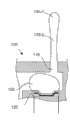
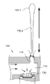
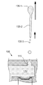
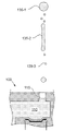
图1A-1F是根据本文所描述原理一个实施例的热喷射微滴发生器操作的示意图。 1A-1F are schematic illustrations of the operation of a thermal jet droplet generator, according to one embodiment of principles described herein.
图2是根据本文所描述原理一个实施例的示意性喷嘴几何结构的图示。 Fig. 2 is an illustration of a schematic nozzle geometry, according to one embodiment of principles described herein.
图3是根据本文所描述原理一个实施例的示意性喷嘴几何结构的图示。 Fig. 3 is an illustration of a schematic nozzle geometry, according to one embodiment of principles described herein.
图4A-4H是根据本文所描述原理一个实施例的、通过非圆形喷嘴喷射微滴的示意性微滴发生器的图示。 4A-4H are illustrations of an illustrative droplet generator ejecting droplets through a non-circular nozzle, according to one embodiment of principles described herein.
图5A和图5B分别是根据本文所描述原理一个实施例的、从圆形和非圆形喷嘴喷射的微滴的示意图。 5A and 5B are schematic illustrations of droplets ejected from circular and non-circular nozzles, respectively, according to one embodiment of principles described herein.
图6A和图6B分别是根据本文所描述原理一个实施例的、由具有圆形喷嘴和非圆形喷嘴的喷墨打印头产生的图像的示意图。 6A and 6B are schematic diagrams of images produced by an inkjet printhead having circular and non-circular nozzles, respectively, according to one embodiment of principles described herein.
图7A和图7B是根据本文所描述原理一个实施例的、喷墨喷嘴和底层电阻器的示意图。 7A and 7B are schematic diagrams of an inkjet nozzle and underlying resistors, according to one embodiment of principles described herein.
图8包括根据本文所描述原理一个实施例的多个示意性孔口几何结构的图示。 FIG. 8 includes illustrations of several exemplary orifice geometries, according to one embodiment of principles described herein.
图9A和图9B是根据本文所描述原理一个实施例的示意性非圆形喷射喷嘴的图示。 9A and 9B are illustrations of schematic non-circular spray nozzles, according to one embodiment of principles described herein.
在所有附图中,相同的附图标记标示了相似但不一定相同的元件。 Throughout the drawings, identical reference numbers designate similar, but not necessarily identical, elements.
具体实施方式 Detailed ways
如上文所述,喷墨打印过程通过从喷嘴喷射流体微滴来将流体沉积在基板上。通常,喷墨装置包含一大列喷嘴,在打印中这些喷嘴每秒喷射几千个微滴。例如,在热喷墨中,打印头包括被连接到一个或多个流体储器的微滴发生器阵列。每个微滴发生器包括加热元件,喷发室和喷嘴。来自储器的流体填充喷发室。为了喷射微滴,电流流过邻近喷发室设置的加热器元件。加热元件产生热,热使喷发室内的一小部分流体蒸发。蒸汽快速膨胀,迫使小的微滴离开喷发室喷嘴。电流然后被关断,电阻器冷却。蒸汽气泡快速崩溃,使更多的流体从储器进入到喷发室中。 As mentioned above, the inkjet printing process deposits fluid on a substrate by ejecting fluid droplets from nozzles. Typically, an inkjet device contains a large array of nozzles that eject thousands of droplets per second during printing. For example, in thermal inkjet, a printhead includes an array of droplet generators connected to one or more fluid reservoirs. Each droplet generator includes a heating element, firing chamber and nozzle. Fluid from the reservoir fills the firing chamber. To eject the droplets, electrical current is passed through a heater element disposed adjacent the firing chamber. The heating element generates heat which vaporizes a small portion of the fluid within the firing chamber. The steam expands rapidly, forcing small droplets out of the blast chamber nozzle. The current is then turned off and the resistor cools. The vapor bubbles collapse quickly, allowing more fluid to pass from the reservoir into the firing chamber.
理想情况下,每个喷发事件会使单个微滴沿预定矢量以预定速度前进,并沉积在基材上的期望位置。然而,由于在流体被喷射以及通过空气时施加到流体的力,原来的微滴可能分裂成多个子微滴。非常小的子微滴可能很快失去速度,在加长的时间周期中保持在空中。这些非常小的子微滴可能产生各种问题。例如,子微滴可沉积在基材上不恰当的位置上,这可能会降低打印机产生的图像的打印质量。子微滴还可沉积在打印设备上,使污垢积累,性能恶化,引起可靠性问题并增加维修成本。 Ideally, each firing event would cause a single droplet to travel along a predetermined vector at a predetermined velocity and deposit at a desired location on the substrate. However, due to the forces applied to the fluid as it is sprayed and passed through the air, the original droplet may break up into multiple sub-droplets. Very small sub-droplets may quickly lose velocity, remaining airborne for extended periods of time. These very small sub-droplets can cause various problems. For example, sub-droplets may be deposited in inappropriate locations on the substrate, which may degrade the print quality of images produced by the printer. Sub-droplets can also deposit on printing equipment, allowing fouling to accumulate, deteriorating performance, causing reliability issues and increasing maintenance costs.
可以用来降低空中子微滴效应的一种方案是捕获并容纳它们。可用各种方法来捕获子微滴。例如,可通过过滤器循环打印机内的空气,过滤器去掉了空中子微滴。额外地或替代性地,静电力可用来吸引、捕获子微滴。然而,这些方案中的每种方案都要求将另外的设备并入打印机中。这使打印机更大、更贵,消耗更多的能量且维护费用更高。 One approach that can be used to reduce the effects of aerial electron droplets is to trap and contain them. Various methods can be used to capture sub-droplets. For example, air within a printer can be circulated through a filter that removes airborne sub-droplets. Additionally or alternatively, electrostatic forces can be used to attract, capture sub-droplets. However, each of these solutions requires additional equipment to be incorporated into the printer. This makes the printer larger, more expensive, consumes more power and is more expensive to maintain.
一种替代性方案是将微滴发生器设计成使趋于裂开所喷射微滴的速度差减至最小。这直接降低了空中子微滴的形成。我们发现,喷墨喷嘴的形状在喷射过程中可被改变以降低可能会使微滴裂开的这些速度差。具体地,具有平滑轮廓且该轮廓带有进入到喷嘴孔口中心的一个或多个突起的喷墨喷嘴降低了所喷射微滴内的速度差,抵消了粘滞力,防止了微滴裂开。 An alternative is to design the droplet generator to minimize velocity differences that tend to break apart the ejected droplets. This directly reduces the formation of neutron droplets. We have found that the shape of the inkjet nozzle can be altered during jetting to reduce these velocity differences that could break apart the droplets. In particular, an inkjet nozzle having a smooth profile with one or more protrusions into the center of the nozzle orifice reduces velocity differences within the ejected droplets, counteracts viscous forces, and prevents droplet break-up. .
在下文的描述中,出于解释的目的,给出了许多具体细节,以便提供对本发明系统和方法的彻底理解。然而,对于本领域技术人员而言,明显的是,没有这些具体细节,也可实践本发明的设备、系统和方法。在说明书中,提到“实施例”,“例子”或类似用语时,表示联系该实施例或例子所描述的具体特征、结构或特性被包括于至少该实施例中,但不一定被包括于其它实施例中。说明书各处中的用语“在一个实施例中”或类似用语的各种情况并不一定全部表示相同的实施例。 In the following description, for purposes of explanation, numerous specific details are given in order to provide a thorough understanding of the systems and methods of the present invention. It will be apparent, however, to one skilled in the art that the devices, systems and methods of the present invention may be practiced without these specific details. In the description, when referring to "embodiment", "example" or similar terms, it means that the specific features, structures or characteristics described in connection with the embodiment or example are included in at least the embodiment, but not necessarily included in the In other embodiments. The various instances of the phrase "in one embodiment" or similar phrases in various places in the specification do not necessarily all refer to the same embodiment.
图1A-1F示出了从热喷墨微滴发生器喷射的微滴的示意性时间顺序。图1A是热喷墨打印头中微滴发生器100的一个示例性实施例的横截面视图。微滴发生器100包括喷发室110,喷发室流体连接到流体储器105。加热元件120邻近喷发室110定位。流体107从流体储器105进入喷发室110。在均衡条件下,流体并不会退出圆形喷嘴115,而是在喷嘴出口内形成凹形弯月面。
1A-1F show a schematic chronological sequence of droplets ejected from a thermal inkjet droplet generator. Figure 1A is a cross-sectional view of an exemplary embodiment of a
图1B是从喷发室110喷射微滴135的微滴发生器100的横截面视图。根据本发明的一个实施例,通过向加热元件120施加电压125,将流体微滴135从喷发室110喷射出。加热元件120可以是电阻性材料,该电阻性材料会因其对电流的内阻而快速变热。由加热元件120产生的热的一部分通过喷发室110的壁,蒸发掉非常接近加热元件120的一小部分流体。流体的蒸发产生快速膨胀的蒸汽气泡130,其克服了喷发室110和圆形喷嘴115内流体中存在的毛细管力。当蒸汽继续膨胀时,微滴135从圆形喷嘴115中喷射出。
FIG. 1B is a cross-sectional view of
在图1C中,去掉了加热元件120的电压,加热元件快速冷却。蒸汽气泡130由于惯性效应继续膨胀。在快速的热损失和继续膨胀的复合影响下,蒸汽气泡130内的压力快速下降。在其最大尺寸时,蒸汽气泡130可能具有相对大的负内压。
In FIG. 1C, the voltage to the
微滴135继续被迫从喷发室出来,形成微滴头部135-1和微滴尾部135-2,微滴头部具有相对高的速度,而微滴尾部具有较低的速度。
The
图1D示出了蒸汽气泡130的快速崩溃。这种快速崩溃导致蒸发室110中出现低压力,其将液体从入口端口和圆形喷嘴115两者中吸入喷发室110。这一突然的压力反向会将最新从喷嘴115冒出的微滴尾部135-2的一部分吸回喷嘴115中。此外,由于微滴尾部的粘滞吸引会阻止微滴135分离,使得微滴尾部135-2的整体速度被降低。在此阶段,喷发室110中的低压还趋向于将外部的空气吸入圆形喷嘴115中。
ID shows the rapid collapse of vapor bubbles 130 . This rapid collapse results in a low pressure in the
微滴135右侧的黑色箭头图解说明了在气泡130崩溃中各部分微滴的相对速度。箭头之间的间隙指示微滴尾部135-2的速度为0的停滞点。
The black arrows to the right of
图1E示出了在停滞点或其附近快速分离的微滴135。微滴尾部135-2猛烈断开产生了大量的子微滴或卫星微滴(satellite droplet)135-3。这些子微滴135-3具有相对低的质量,并且可能具有非常低的速度。即使子微滴135-3具有一定的速度,由于低质量的子微滴135-3与周围空气相互作用,也会相对快速地损失掉该速度。结果,子微滴135-3可能在加长的时间周期里保持在空中。如上文讨论的,子微滴135-3在接触并粘到表面之前可相对漂移较长距离。如果子微滴135-3粘到目标表面,则通常会由于它们落在了目标区域之外而引起打印缺陷。如果子微滴135-3落在了打印设备上,则它们可能产生沉积,这损坏了打印装置的操作,并且造成了维修问题。
Figure IE shows a
微滴尾部135-2和微滴头部135-1之间的速度差还可能引起子微滴的分离和生成。如图1E所示,相对较大的微滴头部135-1具有的速度(如微滴头部左侧的黑色箭头所示)比微滴尾部135-2的速度(由微滴尾部左侧的较短箭头)大。这可能引起微滴头部135-1脱离微滴尾部135-2。 The difference in velocity between the droplet tail 135-2 and the droplet head 135-1 may also cause separation and generation of sub-droplets. As shown in Figure 1E, the relatively larger droplet head 135-1 has a faster velocity (shown by the black arrow to the left of the droplet head) than the velocity of the droplet tail 135-2 (shown by the black arrow to the left of the droplet tail). shorter arrows) large. This may cause the droplet head 135-1 to disengage from the droplet tail 135-2.
图1F示出了由于微滴头部135-1和微滴尾部135-2之间的速度差造成的微滴头部135-1与微滴尾部135-2的分离。这产生了额外的子微滴135-3。 Figure IF shows the separation of the droplet head 135-1 from the droplet tail 135-2 due to the velocity difference between the droplet head 135-1 and the droplet tail 135-2. This produces an additional daughter droplet 135-3.
已经发现,在喷墨打印头的喷射过程中可能会使微滴散开的速度差可通过改变喷墨喷嘴的形状而被降低。常规上,喷墨喷嘴的孔口是圆形的。这些圆形的喷嘴易于制造,并具有高的抗阻塞力。但是,如上所示,在喷射过程中,从圆形喷嘴喷射的微滴具有速度差,这可使微滴分裂开。具体地,在气泡崩溃时微滴尾部的有力收缩可能使尾部的最尾端部分散开,微滴头部和尾部的最前面部分之间的速度差可引起头部和尾部的分离。这些散开事件产生了小的子微滴,这会产生如上文所述的可靠性问题。 It has been found that the velocity difference that may cause droplets to scatter during ejection from an inkjet printhead can be reduced by changing the shape of the inkjet nozzle. Conventionally, the orifice of an inkjet nozzle is circular. These round nozzles are easy to manufacture and have a high resistance to clogging. However, as shown above, the droplets ejected from the circular nozzles have a velocity difference during ejection, which can cause the droplets to break apart. Specifically, the forceful contraction of the droplet tail upon bubble collapse may cause the tailmost portion of the tail to scatter, and the velocity difference between the droplet head and the anteriormost portion of the tail may cause separation of the head and tail. These break-up events create small sub-droplets, which can create reliability issues as described above.
通过为喷墨喷嘴使用非圆形形状,可以降低这些速度差。图2示出了6个非圆形的喷嘴孔口几何形状,它们被构造并被测试以弄清楚它们的性能特性。这6个形状是:多义形-宽形(poly-wide),多义形-椭圆形(poly-ellipse),哑铃形,钝箍缩部形(blunt pinch),数字8形和卵形。这些形状的理论轮廓200示于图2的第一行。理论轮廓200被示为虚线,其代表了形成喷嘴形状的基础的几何形状。具有沉孔的喷嘴孔口的第一种实施方式205被示于第二行,不具有沉孔的喷嘴的第二种实施方式210被示于第三行。在将这些几何形状转换成外轮廓以及构造出喷嘴205,210时,这些几何形状可被改变。例如,数字“8”的理论轮廓包括两个搭接的圆。而在实施时,数字“8”形的喷嘴具有更加平滑的轮廓。 These velocity differences can be reduced by using non-circular shapes for inkjet nozzles. Figure 2 shows six non-circular nozzle orifice geometries that were constructed and tested to clarify their performance characteristics. The six shapes are: poly-wide, poly-ellipse, dumbbell, blunt pinch, figure 8, and oval. Theoretical profiles 200 of these shapes are shown in the first row of FIG. 2 . The theoretical profile 200 is shown as a dashed line representing the geometry that forms the basis of the nozzle shape. A first embodiment 205 of a nozzle orifice with a counterbore is shown in the second row and a second embodiment 210 of a nozzle without a counterbore is shown in the third row. These geometries can be changed when converting them into outer contours and constructing the nozzles 205 , 210 . For example, the theoretical outline of the number "8" consists of two overlapping circles. In practice, the figure "8" shaped nozzle has a smoother profile.
基于实验结果,多义形-椭圆形设计被选择以用于进一步的实验。图3示出了多义形-椭圆形喷嘴300的示意图。根据此示意性实施例,多义形-椭圆形孔口302的形状是由下面示出的四次多项式定义的。
Based on the experimental results, a polysemy-ellipse design was selected for further experiments. FIG. 3 shows a schematic diagram of a poly-
方程1。 Equation 1.
如图3所示示意性例子所显示的,此多变量多项式产生了一个具有数学平滑和数学连续轮廓的闭合形状。如说明书和所附权利要求中使用的,术语“数学平滑”指的是一类具有所有适合阶数的导数的函数。术语“数学连续”指的是一种输入的小变化会产生输出的小变化的函数。术语“闭合”指的是这样一些函数,它们限定出或围出了一个平面或其它图形空间的一个区域,使得从该封闭区域的内部到外部的路径必须穿过由该函数限定的边界。图3所示的孔口形状由具有方程1所示通式的单个方程产生。具体地,该孔口形状不是通过全异方程以分段方式产生的线连接而产生的。 As shown in the schematic example shown in Figure 3, this multivariate polynomial produces a closed shape with a mathematically smooth and mathematically continuous contour. As used in the specification and appended claims, the term "mathematically smooth" refers to a class of functions having derivatives of all appropriate orders. The term "mathematically continuous" refers to a function in which small changes in the input produce small changes in the output. The term "closed" refers to functions that define or enclose a region of a plane or other graphic space such that a path from the interior to the exterior of the closed region must pass through the boundaries defined by the function. The orifice shape shown in Figure 3 results from a single equation with the general formula shown in Equation 1. In particular, the orifice shape is not produced by line connections produced piecewise by disparate equations.
已经发现,具有相对平滑轮廓的喷嘴孔口更有效地允许流体从喷发室出来。具体地,具有突然轮廓变化的喷嘴,如图2所示的卵形轮廓在产生给定大小的微滴方面,每单位面积上并不那么有效。例如,为了产生9微克的微滴,卵形轮廓相比于具有更平滑的轮廓线的多义形-椭圆形轮廓要求更大的横截面面积。 It has been found that nozzle orifices having a relatively smooth profile are more effective in allowing fluid to exit the firing chamber. In particular, nozzles with abrupt profile changes, such as the oval profile shown in Figure 2, are not as effective per unit area at producing droplets of a given size. For example, to produce a 9 microgram droplet, an oval profile requires a larger cross-sectional area than a poly-ellipse profile with smoother contour lines.
为了产生与图3所示类似的形状,可以将下面的常数代入到上面的方程1中。 To produce a shape similar to that shown in Figure 3, the following constants can be substituted into Equation 1 above. the
表1 Table 1
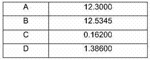
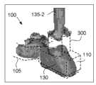
这一多义形-椭圆形形状限定了用在喷嘴300中的非圆形孔口302。非圆形孔口302具有两个椭圆瓣325-1,325-2。在椭圆瓣325之间,两个突起310-1,310-2朝喷嘴300的中心延伸,产生收缩的喉部320。喉部最窄部分上的测量值被称作喉部320的“箍缩距(pinch)”。
This polygonal-elliptical shape defines a
对流体流动的阻力与喷嘴给定部分的横截面面积成比例。具有较小横截面的喷嘴部分对流体流动具有更高的阻力。突起310在孔口302的中心部分产生相对高的流体阻力区域315。相反,瓣325-1,325-2具有大得多的横截面,因而限定了较低流体阻力305-1,305-2的区域。
The resistance to fluid flow is proportional to the cross-sectional area of a given portion of the nozzle. A nozzle portion with a smaller cross-section has a higher resistance to fluid flow. The protrusion 310 creates a relatively high
孔口302的主轴线328和次轴线330被图示为穿过多义形-椭圆形喷嘴300的箭头。主轴线328对分了椭圆瓣325。次轴线330对分了突起310,并横跨穿过了孔口302的喉部320区域。根据一个示例性实施例,孔口302的包络线335被图示为一个灰色矩形,其在主轴线和次轴线328,330上界定了孔口302。根据一个示意性实施例,孔口302的包络线335可以约是20微米×20微米。此相对紧凑的尺寸允许喷嘴300被用在每个线性英寸有大约1200个喷嘴的打印头配置中。
The
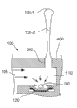
图4A-4C描述了流体微滴315从包括多义形-椭圆形喷嘴300的微滴发生器100的喷射。如图4A所示,微滴发生器100包括喷发室110,喷发室流体连接到流体储器105。具有多义形-椭圆形孔口的喷嘴300形成通过顶盖层400的通道。加热电阻器120产生蒸汽气泡130,蒸汽气泡快速膨胀以将微滴315压出喷发室110,并通过喷嘴300到外部。如上文讨论的,较大体积和速度的流体从孔口302的更加开阔的横截面出来。结果,微滴135更快速地从瓣325-1,325-2的开阔横截面305-1,305-2(图3)出来。多义形-椭圆形孔口302的喉部320的受限横截面具有更高的流体流动阻力。根据一个示例性实施例,因为尾部135-2和喉部320之间的惯性、粘滞和毛细管力,微滴135-2的尾部可自动地和重复地居中于喉部区域320。使微滴135-2的尾部居中于喉部区域320有多个优点。例如,将尾部135-2定位在喉部320的中心可以使留在喷发室110(图1)中液体的尾部135与主体更加可重复的分离。这会保持微滴的尾部135-2与头部135-1对准,改善微滴135的方向性。
4A-4C depict the ejection of
使尾部135-2位于喉部320上方中心的另一优点是在蒸汽气泡崩溃时,喉部320的较高的流体阻力降低了尾部135-2中的速度差。这可以防止在微滴135-1的前面部分继续以大约10米/秒离开喷嘴300时,一部分尾部135-2急速回到喷发室110(图1)的内部时,微滴135被猛烈地撕开。相反,表面张力形成了箍缩距上的墨液桥。在蒸汽气泡崩溃过程中,在墨液被吸回到孔中时,此墨液桥支撑尾部135-2。流体从瓣325吸入,形成弯月面405,弯月面继续被吸入到喷发室110(图1)中。
Another advantage of having the tail 135-2 centered over the
在蒸汽气泡130崩溃时,流体从流体储器105的入口和喷嘴300两者被吸入到喷发室110中。然而,如图4B所示,使尾部135-2位于喉部上方的中心并降低微滴135内的速度差,降低了产生子微滴153-3(图1)的可能性。如果这些相对速度在幅度和方向上足够相似,则表面张力会将尾部135-2向上吸入到微滴头部135-1中。此单个微滴135然后会前进到基板,落在目标位置或接近目标位置。然而,如图4C所示,在此示例中,微滴头部135-1和微滴尾部135-2之间的速度差不够小到使尾部135-2与头部135-1接合。相反,形成了两个微滴:较大的头部微滴135-1和较小的尾部微滴135-2。
As the
根据一个示例性实施例,微滴发生器及其喷嘴可被设计成重复地产生质量在6纳克到12纳克范围内的微滴。例如,微滴发生器和喷嘴可被配置成产生9纳克质量的微滴。 According to an exemplary embodiment, the droplet generator and its nozzles may be designed to repeatedly generate droplets with a mass in the range of 6 nanograms to 12 nanograms. For example, the droplet generator and nozzle can be configured to produce droplets of 9 nanogram mass.
图4D-4H更加详细地聚焦于蒸汽气泡崩溃,尾部分离和弯月面回缩到喷发室中。在图4D-4H中,虚线表示微滴发生器100的内表面。纹理形状表示液体/蒸汽表面。图4D示出了接近其最大尺寸的蒸汽气泡130。蒸汽气泡130填满了喷发室110的大部分,并延伸出来再进入到墨液储器105。微滴的尾部135-2延伸出喷嘴300。图4E示出了蒸汽气泡130开始崩溃以及微滴的尾部开始变细。图4F示出了蒸汽气泡130继续崩溃,当崩溃的气泡130从外部将空气吸入到喷嘴300中时,弯月面405开始在喷嘴300中形成。从图4F可以看出,弯月面405形成了两个瓣,它们与多义形-椭圆形喷嘴300的两个瓣相对应。尾部135-2保持居中于喷嘴300的中心上方。如上文讨论的,分离时尾部135-2的位置可影响微滴的轨迹。
Figures 4D-4H focus in more detail on vapor bubble collapse, tail separation and meniscus retraction into the eruption chamber. In FIGS. 4D-4H , the dashed lines represent the inner surface of the
图4G示出了蒸汽气泡130已经完全从墨液储器105返回,并开始分成两个单独的气泡。弯月面405继续加深进入喷发室110中,表示空气被吸入到喷发室110中。在这点尾部135-2与喷嘴300分离,从喷嘴300中心上方的中性位置分开。
Figure 4G shows that the
图4H示出了尾部135-2已经完全与喷嘴400分离。尾部135-2中的表面张力开始将尾部底部的大部分向上吸引到尾部的主要部分中。这导致尾部135-2具有轻微的球形端。蒸汽气泡130已经崩溃成两个单独的气泡,这两个气泡位于喷发室110的角落中。弯月面405延伸进入到喷发室110中。如上文讨论的,在微滴从包括多义形-椭圆形喷嘴300的微滴发生器100喷射的过程中,存在数目降低的卫星微滴。
Figure 4H shows that tail portion 135-2 has been completely separated from
图5A和图5B是图解说明从图1A-1F所示的圆形喷嘴阵列中喷射的墨液微滴以及从图4A-4F所示的多义形-椭圆形喷嘴阵列中喷射的墨液微滴的实际图像的图示。从图5A可以看出,从打印头500中的圆形喷嘴喷射的微滴被散开成许多不同的子微滴135-3。这产生了各种大小的微滴135薄雾。如上文讨论的,质量减小的子微滴135-3会很快失去速度,可在很长的时间周期保持在空中。
5A and FIG. 5B are diagrams illustrating ink droplets ejected from the circular nozzle array shown in FIGS. Illustration of the actual image of the droplet. It can be seen from FIG. 5A that the droplets ejected from the circular nozzles in the
图5B是从打印头500的多义形-椭圆形喷嘴300喷射微滴135的图示。在此情况下,微滴135一致地只形成头部微滴135-1和尾部微滴135-2。几乎没有存在更小子微滴的迹象。头部微滴135-1和尾部微滴135-2可在飞行中合并和/或可撞击基板的相同区域。
FIG. 5B is an illustration of
图6A和图6B图解说明了对比圆形喷嘴和示意性多义形-椭圆形喷嘴的打印质量效果的示意图。图6A的左手侧图解说明了圆形喷嘴115和底层电阻器的相对方向和大小。图6A的右手侧是使用圆形喷嘴产生的一部分文本的照片615。文本是四点字体的英语单词“The”。在照片615中清楚可见的是,由具有较低速度的中等质量子微滴产生的文本边缘。这些子微滴未撞击到期望位置,导致图像模糊。如上文讨论的,质量最轻的子微滴可能不曾接触到该基板。
6A and 6B illustrate schematic diagrams comparing the print quality effects of circular nozzles and illustrative poly-elliptical nozzles. The left hand side of Figure 6A illustrates the relative orientation and size of the
图6B的左手侧示出了一个多义形-椭圆形喷嘴300,其垂直于底层的加热电阻器600。如右手照片610中所示的,相同字体的相同单词是使用多义形-椭圆形喷嘴300设计打印的。关于边缘清晰度,由多义形-椭圆形喷嘴300产生的打印质量明显好于圆形喷嘴115。显然不存在表示微滴破裂的相对较小的点。较大微滴尺寸的另一结果是可用更大的准确度设置微滴。单词“The”各字母的内部示出了这些字母内部的大量的明亮/黑暗的纹理或“颗粒”。这是较大微滴尺寸更准确地前进到目标位置的结果。例如,如果每个喷射周期产生两个微滴,则头部微滴和尾部微滴两者都可落在相同位置。这可能在目标位置之间产生空白空间。
The left hand side of FIG. 6B shows a polygonal-
各种参数可被选择或改变以优化多义形-椭圆形喷嘴300的性能。这些参数反映了可能影响喷嘴的性能的宽范围的各种因素。除了喷嘴的形状之外,墨液的特性可影响喷嘴的性能。例如,粘滞力,表面张力和墨液成分可影响喷嘴性能。
Various parameters may be selected or varied to optimize the performance of the poly-
图7A和图7B图解说明了可被调节以改变喷嘴性能的一个参数。具体地,可以调节馈送槽600相对于喷嘴300的取向。馈送槽600是形成主墨液储器和沿馈送槽600各侧排列的多个喷发室110之间的流体连接的孔口。根据图7A所示的一个示意性实施例,喷嘴300的主轴线328平行于馈送槽605的主轴线605。在此实施例中,多义形-椭圆形喷嘴300的两个瓣与馈送槽600有相等距离,表现出大致相同的行为。然而,图7B示出了馈送槽600的主轴线605和垂直取向的喷嘴300的主轴线328。在此配置中,其中的一个瓣位于喷发室内与另一瓣相隔不同的距离处。这在两个瓣中产生了不对称的流体行为。在一些应用中,这可能是有利的。
7A and 7B illustrate one parameter that can be adjusted to change nozzle performance. In particular, the orientation of the
在微滴发生器内可以调节各种其它参数。例如,加热电阻器600的大小和尺寸可影响一次喷发序列中蒸汽气泡的几何形状。而蒸汽气泡又会影响所喷射微滴的特性。
Various other parameters can be adjusted within the droplet generator. For example, the size and dimensions of the
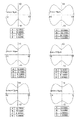
可以调节的另一个参数是多义形-椭圆形轮廓的几何形状。图8包括多个示意性的多义形-椭圆形轮廓,这可通过调节方程1中的参数来产生。图8中的每个示意性实例包括具有喉部箍缩距的轮廓,并列出方程1中用来产生几何形状的参数。此轮廓被叠加在图形上,图形以微米为单位显示X和Y的距离。例如,在左上角的示意性示例中,多义形-椭圆形轮廓的周边沿X轴线从延伸大约10微米到-10微米。喉部8中最窄点的箍缩距是8微米。 Another parameter that can be tuned is the geometry of the poly-ellipse profile. FIG. 8 includes a number of illustrative polymorphic-elliptical profiles, which can be generated by adjusting the parameters in Equation 1. FIG. Each schematic example in FIG. 8 includes a profile with a throat pinch and lists the parameters used in Equation 1 to generate the geometry. This profile is overlaid on a graph showing the X and Y distances in microns. For example, in the schematic example on the upper left, the perimeter of the poly-ellipse profile extends approximately 10 microns to -10 microns along the X-axis. The pinch at the narrowest point in the throat 8 is 8 microns.
其它示意性示例具有逐渐更大的箍缩距。右下侧的示例具有最开阔的轮廓,其具有13微米的箍缩距。更加开阔的轮廓具有更大的流体流动,受阻的可能更小,如果阻碍出现,更易于清除。然而,轮廓的喉部越宽,突起在降低微滴破裂方面的效果更小。 Other illustrative examples have progressively larger pinch distances. The example on the lower right has the widest profile with a pinch of 13 microns. The more open profile has greater fluid flow, is less likely to get stuck, and is easier to clear if a blockage occurs. However, the wider the throat of the profile, the less effective the protrusions are in reducing droplet breakup.
对于每个图形,给出了对应的表,其具有可代入方程1中以产生图示形状的常数。这些常数只是示意性的示例。可以使用各种其它的常数来产生具有相同喉部箍缩距的形状。例如,可使用图8左下侧的表来产生12微米喉部箍缩距。然而,可通过将下列常数代入方程1中来产生具有12微米喉部箍缩距的类似形状。 For each graph, a corresponding table is given with constants that can be substituted into Equation 1 to generate the graphed shape. These constants are illustrative examples only. Various other constants can be used to produce shapes with the same throat pinch. For example, a 12 micron throat pinch can be generated using the table on the lower left of FIG. 8 . However, a similar shape with a 12 micron throat pinch can be produced by substituting the following constants into Equation 1. the
表2 Table 2

将表2与图8的左下表比较,显然在产生相同的喉部箍缩距时各常数可被增大、减小或保持相同。例如,常数A保持相同,B稍微减小,C已经降低了图8所示值的接近一半,而D增大了。 Comparing Table 2 with the lower left table of Figure 8, it is evident that the constants can be increased, decreased or kept the same while producing the same throat pinch. For example, the constant A remains the same, B has decreased slightly, C has decreased by nearly half of the value shown in Figure 8, and D has increased.
这些常数可以从一系列的值中选择以产生期望形状。例如,A可具有大约9-14的范围,B可具有大约9-14的范围,C可具有大约0.001-1的范围,D可具有大约0.5-2的范围。在另一实施例中,A可具有大约12.0-13.0的范围,B可具有大约12.0-13.0的范围,C可具有大约0.001-0.5的范围,D可具有大约1-2的范围。 These constants can be chosen from a range of values to produce the desired shape. For example, A may have a range of about 9-14, B may have a range of about 9-14, C may have a range of about 0.001-1, and D may have a range of about 0.5-2. In another embodiment, A may have a range of about 12.0-13.0, B may have a range of about 12.0-13.0, C may have a range of about 0.001-0.5, and D may have a range of about 1-2.
这些常数可被选择成使得所得到的由所述多项式限定的喷嘴产生具有期望墨滴质量的微滴。例如,箍缩距的范围可从3-14微米,墨滴的质量范围从4纳克-15纳克。如上文讨论的,各种常数值可被选择以产生期望的几何形状。另外,可使用许多其它方程来产生箍缩式椭圆形式。 These constants can be chosen such that the resulting nozzle defined by the polynomial produces droplets with a desired drop mass. For example, the pinch distance can range from 3-14 microns, and the droplet mass can range from 4 nanograms to 15 nanograms. As discussed above, various constant values can be selected to produce the desired geometry. Additionally, many other equations can be used to generate the pinched elliptical form.
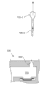
图9A-9B是多义形-椭圆形喷嘴的一个示意性实施例的照片图像。图9A是俯视图,其示出了具有喉部320的多义形-椭圆形喷嘴300。在此示意性实施例中,沉孔900已经形成。虚线905标记了沉孔900的起始部。如在说明书和所附权利要求中使用的,术语“沉孔”是指喷嘴300周界周围相对较浅的凹陷或其它切口区域。此沉孔900可具有各种形状、宽度和大小。
9A-9B are photographic images of one illustrative embodiment of a poly-ellipse nozzle. FIG. 9A is a top view showing poly-
图9B是喷嘴300沿图9A中的线9B-9B剖切的横截面图。线9B-9B穿过喷嘴300的喉部320。此横截面示出了穿过顶盖层400的喷嘴300。顶盖层400包括内表面400-2和外表面400-1,内表面形成喷发室110的室顶,外表面形成微滴发生器的外表面。根据一个示意性实施例,顶盖层400由SU-8(一种基于环氧树脂的负性光刻胶)形成。顶盖层400可以各种厚度形成。例如,顶盖层400可以为20微米厚。
9B is a cross-sectional view of the
在此示例性实施例中,沉孔900是浅的碟状凹陷。沉孔900可用于许多功能,包括从轮廓的上周边去掉任何毛刺或其它制造缺陷。此外,形成喷嘴300的周界壁910可以是有锥度的。在此示意性实施例中,喷嘴300的周界壁910向外翻大约12度角。在其它实施例中,此外翻角范围可以从5-15度。结果,喷嘴喉部320在内部表面400-2处较宽,而在进入沉孔900之前变窄。
In the exemplary embodiment,
孔口302的沉孔900和锥形部920可以各种方式形成,包括Shaarawi等人2005年1月31申请的美国专利No. 7,585,616中描述的那些方式,在此通过引用将该专利整个并入本文。
The
总之,由多项式限定的多义形-椭圆形喷嘴形成具有平滑和连续轮廓线的孔口,其具有两个突起,这两个突起延伸进孔口中心,形成喉部。此喷嘴的几何形状使穿过孔口中心的流体变慢,减小了被喷射微滴内的速度差。这降低了被喷射微滴的破裂,提高了微滴轨迹的重复性和精度。在微滴从微滴发生器分离的过程中,喷嘴几何形状还允许尾部居中于喉部上方。这产生了微滴尾部从微滴发生器的更加轻柔的分离,以及在气泡崩溃过程中返回喷发室中的尾部不那么强的收缩。这降低了分离过程中尾部的破裂,防止了尾部使微滴轨迹变歪。 In summary, a polynomial-elliptical nozzle defined by a polynomial forms an orifice with a smooth and continuous contour with two protrusions extending into the center of the orifice, forming the throat. The geometry of this nozzle slows the flow through the center of the orifice, reducing the velocity differential within the ejected droplets. This reduces breakup of ejected droplets and improves the repeatability and precision of droplet trajectories. The nozzle geometry also allows the tail to be centered over the throat during droplet separation from the droplet generator. This produces a more gentle detachment of the droplet tail from the droplet generator, and a less strong constriction of the tail back into the firing chamber during bubble collapse. This reduces breakage of the tail during separation, preventing the tail from skewing the droplet trajectory.
前面的描述只是为了图解说明和描述本文所述原理的实施例和示例而给出的。这些描述不是排他性的,也不应将那些原理限制到所公开的任何精确形式。根据上面的教导,可作出许多变型和修改。 The foregoing description has been presented only to illustrate and describe embodiments and examples of the principles described herein. These descriptions are not exhaustive, nor should they limit those principles to any precise form disclosed. Many variations and modifications are possible in light of the above teaching.
Claims (15)
Applications Claiming Priority (1)
| Application Number | Priority Date | Filing Date | Title |
|---|---|---|---|
| PCT/US2010/029450 WO2011123120A1 (en) | 2010-03-31 | 2010-03-31 | Noncircular inkjet nozzle |
Publications (2)
| Publication Number | Publication Date |
|---|---|
| CN102905902A true CN102905902A (en) | 2013-01-30 |
| CN102905902B CN102905902B (en) | 2016-03-09 |
Family
ID=44712539
Family Applications (2)
| Application Number | Title | Priority Date | Filing Date |
|---|---|---|---|
| CN201080067187.7A Active CN102905902B (en) | 2010-03-31 | 2010-03-31 | Noncircular inkjet nozzle |
| CN201180027022.1A Active CN103328217B (en) | 2010-03-31 | 2011-01-20 | Non-circular inkjet nozzle |
Family Applications After (1)
| Application Number | Title | Priority Date | Filing Date |
|---|---|---|---|
| CN201180027022.1A Active CN103328217B (en) | 2010-03-31 | 2011-01-20 | Non-circular inkjet nozzle |
Country Status (5)
| Country | Link |
|---|---|
| US (3) | US10112393B2 (en) |
| EP (2) | EP2552701B1 (en) |
| KR (2) | KR101657337B1 (en) |
| CN (2) | CN102905902B (en) |
| WO (2) | WO2011123120A1 (en) |
Cited By (5)
| Publication number | Priority date | Publication date | Assignee | Title |
|---|---|---|---|---|
| CN105358324A (en) * | 2013-07-09 | 2016-02-24 | 佳能株式会社 | Liquid ejection head and method of manufacturing the liquid ejection head |
| CN106255601A (en) * | 2014-04-29 | 2016-12-21 | 惠普发展公司有限责任合伙企业 | Image content-based selects nozzle rows |
| CN107000438A (en) * | 2014-10-30 | 2017-08-01 | 惠普发展公司,有限责任合伙企业 | Inkjet printing |
| CN107073948A (en) * | 2014-10-30 | 2017-08-18 | 惠普发展公司,有限责任合伙企业 | inkjet printing |
| CN110385914A (en) * | 2018-04-17 | 2019-10-29 | 佳能株式会社 | Liquid ejecting head |
Families Citing this family (11)
| Publication number | Priority date | Publication date | Assignee | Title |
|---|---|---|---|---|
| KR101657337B1 (en) | 2010-03-31 | 2016-09-19 | 휴렛-팩커드 디벨롭먼트 컴퍼니, 엘.피. | Noncircular inkjet nozzle |
| US10717278B2 (en) | 2010-03-31 | 2020-07-21 | Hewlett-Packard Development Company, L.P. | Noncircular inkjet nozzle |
| US8807892B2 (en) | 2010-07-30 | 2014-08-19 | Ferus Inc. | Transport tank cradle assembly |
| US10288537B2 (en) | 2013-02-04 | 2019-05-14 | Epona Biotech Ltd | Test fluid collection system |
| US8944549B2 (en) * | 2013-06-24 | 2015-02-03 | Hewlett-Packard Development Company, L.P. | Nozzle layouts for printheads |
| EP3000602B1 (en) * | 2014-09-26 | 2020-07-22 | Agfa Nv | High viscosity jetting method |
| CN107073959B (en) * | 2014-10-30 | 2019-11-12 | 惠普发展公司,有限责任合伙企业 | Method, printing system, and non-transitory machine-readable medium for printing documents |
| US11345162B2 (en) * | 2015-07-14 | 2022-05-31 | Hewlett-Packard Development Company, L.P. | Fluid recirculation channels |
| JP6877970B2 (en) * | 2016-01-08 | 2021-05-26 | キヤノン株式会社 | Liquid discharge head and liquid discharge method |
| JP6860305B2 (en) | 2016-07-22 | 2021-04-14 | キヤノン株式会社 | Liquid discharge head and liquid discharge device |
| JP2019005988A (en) * | 2017-06-23 | 2019-01-17 | キヤノン株式会社 | Liquid discharge head and liquid discharge device |
Citations (10)
| Publication number | Priority date | Publication date | Assignee | Title |
|---|---|---|---|---|
| JPH09131877A (en) * | 1995-10-25 | 1997-05-20 | Hewlett Packard Co <Hp> | Print head |
| EP0792744A2 (en) * | 1996-02-29 | 1997-09-03 | Hewlett-Packard Company | Asymmetric printhead orifice |
| CN1191807A (en) * | 1997-02-25 | 1998-09-02 | 惠普公司 | Inkjet printhead orifices with droplet reduction |
| US6203145B1 (en) * | 1999-12-17 | 2001-03-20 | Eastman Kodak Company | Continuous ink jet system having non-circular orifices |
| US6371596B1 (en) * | 1995-10-25 | 2002-04-16 | Hewlett-Packard Company | Asymmetric ink emitting orifices for improved inkjet drop formation |
| US20040155928A1 (en) * | 2003-02-10 | 2004-08-12 | Clark Garrett E. | Counter-bore of a fluid ejection device |
| US20070146437A1 (en) * | 2005-11-29 | 2007-06-28 | Canon Kabushiki Kaisha | Liquid discharge method, liquid discharge head and liquid discharge apparatus |
| US20080291245A1 (en) * | 2007-05-25 | 2008-11-27 | Canon Kabushiki Kaisha | Liquid ejection head |
| US20090002447A1 (en) * | 2007-05-25 | 2009-01-01 | Canon Kabushiki Kaisha | Liquid ejecting head and ink jet printing apparatus |
| WO2009082391A1 (en) * | 2007-12-20 | 2009-07-02 | Hewlett-Packard Development Company, L.P. | Droplet generator |
Family Cites Families (12)
| Publication number | Priority date | Publication date | Assignee | Title |
|---|---|---|---|---|
| US6254219B1 (en) * | 1995-10-25 | 2001-07-03 | Hewlett-Packard Company | Inkjet printhead orifice plate having related orifices |
| US6860588B1 (en) | 2000-10-11 | 2005-03-01 | Hewlett-Packard Development Company, L.P. | Inkjet nozzle structure to reduce drop placement error |
| SE0003799D0 (en) | 2000-10-20 | 2000-10-20 | Aamic Ab | Method of making holes and structures including such holes |
| JP3873675B2 (en) * | 2001-06-28 | 2007-01-24 | ブラザー工業株式会社 | ink cartridge |
| US7585616B2 (en) * | 2005-01-31 | 2009-09-08 | Hewlett-Packard Development Company, L.P. | Method for making fluid emitter orifice |
| US7445317B2 (en) * | 2005-10-11 | 2008-11-04 | Silverbrook Research Pty Ltd | Inkjet printhead with droplet stem anchor |
| JP4965972B2 (en) | 2006-11-06 | 2012-07-04 | キヤノン株式会社 | Inkjet ejection method |
| JP2008149516A (en) | 2006-12-15 | 2008-07-03 | Canon Inc | Liquid discharge head |
| US7967413B2 (en) | 2007-05-25 | 2011-06-28 | Canon Kabushiki Kaisha | Liquid ejection head and liquid ejection method |
| JP5183181B2 (en) | 2007-12-11 | 2013-04-17 | キヤノン株式会社 | Inkjet recording head |
| US8205338B2 (en) | 2009-08-20 | 2012-06-26 | Eastman Kodak Company | Method of making a multi-lobed nozzle |
| KR101657337B1 (en) | 2010-03-31 | 2016-09-19 | 휴렛-팩커드 디벨롭먼트 컴퍼니, 엘.피. | Noncircular inkjet nozzle |
-
2010
- 2010-03-31 KR KR1020127026531A patent/KR101657337B1/en not_active Expired - Fee Related
- 2010-03-31 US US13/386,866 patent/US10112393B2/en active Active
- 2010-03-31 CN CN201080067187.7A patent/CN102905902B/en active Active
- 2010-03-31 EP EP10849144.0A patent/EP2552701B1/en active Active
- 2010-03-31 WO PCT/US2010/029450 patent/WO2011123120A1/en not_active Ceased
-
2011
- 2011-01-20 WO PCT/US2011/021923 patent/WO2012161671A2/en not_active Ceased
- 2011-01-20 CN CN201180027022.1A patent/CN103328217B/en active Active
- 2011-01-20 KR KR1020127025536A patent/KR101686275B1/en not_active Expired - Fee Related
- 2011-01-20 EP EP11861331.4A patent/EP2646251B1/en active Active
-
2017
- 2017-12-07 US US15/834,353 patent/US10252527B2/en active Active
-
2018
- 2018-09-24 US US16/139,716 patent/US10562304B2/en active Active
Patent Citations (15)
| Publication number | Priority date | Publication date | Assignee | Title |
|---|---|---|---|---|
| US6527369B1 (en) * | 1995-10-25 | 2003-03-04 | Hewlett-Packard Company | Asymmetric printhead orifice |
| JPH09131877A (en) * | 1995-10-25 | 1997-05-20 | Hewlett Packard Co <Hp> | Print head |
| US6123413A (en) * | 1995-10-25 | 2000-09-26 | Hewlett-Packard Company | Reduced spray inkjet printhead orifice |
| US6557974B1 (en) * | 1995-10-25 | 2003-05-06 | Hewlett-Packard Company | Non-circular printhead orifice |
| US6371596B1 (en) * | 1995-10-25 | 2002-04-16 | Hewlett-Packard Company | Asymmetric ink emitting orifices for improved inkjet drop formation |
| EP0792744A2 (en) * | 1996-02-29 | 1997-09-03 | Hewlett-Packard Company | Asymmetric printhead orifice |
| JPH09239986A (en) * | 1996-02-29 | 1997-09-16 | Hewlett Packard Co <Hp> | Printing head with asymmetrical orifice |
| CN1191807A (en) * | 1997-02-25 | 1998-09-02 | 惠普公司 | Inkjet printhead orifices with droplet reduction |
| US6203145B1 (en) * | 1999-12-17 | 2001-03-20 | Eastman Kodak Company | Continuous ink jet system having non-circular orifices |
| US20040155928A1 (en) * | 2003-02-10 | 2004-08-12 | Clark Garrett E. | Counter-bore of a fluid ejection device |
| US20070146437A1 (en) * | 2005-11-29 | 2007-06-28 | Canon Kabushiki Kaisha | Liquid discharge method, liquid discharge head and liquid discharge apparatus |
| CN101316712A (en) * | 2005-11-29 | 2008-12-03 | 佳能株式会社 | Liquid discharge method, liquid discharge head, and liquid discharge apparatus |
| US20080291245A1 (en) * | 2007-05-25 | 2008-11-27 | Canon Kabushiki Kaisha | Liquid ejection head |
| US20090002447A1 (en) * | 2007-05-25 | 2009-01-01 | Canon Kabushiki Kaisha | Liquid ejecting head and ink jet printing apparatus |
| WO2009082391A1 (en) * | 2007-12-20 | 2009-07-02 | Hewlett-Packard Development Company, L.P. | Droplet generator |
Non-Patent Citations (1)
| Title |
|---|
| 王叙贵: "多卵线与多纽线——卡西尼卵形线与伯努利双纽线的推广", 《昆明师范高等专科学校学报》, vol. 23, no. 4, 30 April 2001 (2001-04-30), pages 34 - 36 * |
Cited By (15)
| Publication number | Priority date | Publication date | Assignee | Title |
|---|---|---|---|---|
| CN105358324A (en) * | 2013-07-09 | 2016-02-24 | 佳能株式会社 | Liquid ejection head and method of manufacturing the liquid ejection head |
| US9895887B2 (en) | 2013-07-09 | 2018-02-20 | Canon Kabushiki Kaisha | Liquid ejection head and process for producing the same |
| US10160210B2 (en) | 2014-04-29 | 2018-12-25 | Hewlett-Packard Development Company, L.P. | Selecting a nozzle column based on image content |
| CN106255601A (en) * | 2014-04-29 | 2016-12-21 | 惠普发展公司有限责任合伙企业 | Image content-based selects nozzle rows |
| CN106255601B (en) * | 2014-04-29 | 2019-10-22 | 惠普发展公司有限责任合伙企业 | Method and apparatus for selecting nozzle columns based on image content |
| US10245832B2 (en) | 2014-10-30 | 2019-04-02 | Hewlett-Packard Development Company, L.P. | Ink jet printing |
| CN107073948A (en) * | 2014-10-30 | 2017-08-18 | 惠普发展公司,有限责任合伙企业 | inkjet printing |
| CN107000438B (en) * | 2014-10-30 | 2019-05-31 | 惠普发展公司,有限责任合伙企业 | Printing systems and printheads |
| CN107000438A (en) * | 2014-10-30 | 2017-08-01 | 惠普发展公司,有限责任合伙企业 | Inkjet printing |
| US10661564B2 (en) | 2014-10-30 | 2020-05-26 | Hewlett-Packard Development Company, L.P. | Ink jet printing |
| US10780695B2 (en) | 2014-10-30 | 2020-09-22 | Hewlett-Packard Development Company, L.P. | Ink jet printing |
| US11331918B2 (en) | 2014-10-30 | 2022-05-17 | Hewlett-Packard Development Company, L.P. | Ink jet printing |
| CN110385914A (en) * | 2018-04-17 | 2019-10-29 | 佳能株式会社 | Liquid ejecting head |
| US10875305B2 (en) | 2018-04-17 | 2020-12-29 | Canon Kabushiki Kaisha | Liquid ejection head |
| CN110385914B (en) * | 2018-04-17 | 2021-06-04 | 佳能株式会社 | Liquid ejection head |
Also Published As
| Publication number | Publication date |
|---|---|
| EP2552701A4 (en) | 2018-04-11 |
| CN103328217B (en) | 2016-05-18 |
| WO2012161671A3 (en) | 2013-01-31 |
| US10112393B2 (en) | 2018-10-30 |
| US20130021411A1 (en) | 2013-01-24 |
| EP2552701B1 (en) | 2022-02-23 |
| US10252527B2 (en) | 2019-04-09 |
| WO2012161671A2 (en) | 2012-11-29 |
| CN102905902B (en) | 2016-03-09 |
| US20180104953A1 (en) | 2018-04-19 |
| US20190023010A1 (en) | 2019-01-24 |
| CN103328217A (en) | 2013-09-25 |
| KR20130073868A (en) | 2013-07-03 |
| EP2646251A4 (en) | 2014-12-31 |
| WO2011123120A1 (en) | 2011-10-06 |
| EP2552701A1 (en) | 2013-02-06 |
| US10562304B2 (en) | 2020-02-18 |
| KR101657337B1 (en) | 2016-09-19 |
| EP2646251A2 (en) | 2013-10-09 |
| KR20130018261A (en) | 2013-02-20 |
| EP2646251B1 (en) | 2016-05-04 |
| KR101686275B1 (en) | 2016-12-13 |
Similar Documents
| Publication | Publication Date | Title |
|---|---|---|
| CN102905902B (en) | Noncircular inkjet nozzle | |
| JP4818480B1 (en) | Liquid ejection method | |
| JPH09239986A (en) | Printing head with asymmetrical orifice | |
| US7625080B2 (en) | Air management in a fluid ejection device | |
| US10717278B2 (en) | Noncircular inkjet nozzle | |
| HK1176585A (en) | Noncircular inkjet nozzle | |
| HK1176585B (en) | Noncircular inkjet nozzle | |
| JPH11188876A (en) | Ink jet recording head and ink jet recording apparatus provided with the ink jet recording head |
Legal Events
| Date | Code | Title | Description |
|---|---|---|---|
| C06 | Publication | ||
| PB01 | Publication | ||
| C10 | Entry into substantive examination | ||
| SE01 | Entry into force of request for substantive examination | ||
| C14 | Grant of patent or utility model | ||
| GR01 | Patent grant |