CN102926322A - Construction method, hoisting tool, location tire and location support for installing comb-tooth-shaped expansion joint - Google Patents
Construction method, hoisting tool, location tire and location support for installing comb-tooth-shaped expansion joint Download PDFInfo
- Publication number
- CN102926322A CN102926322A CN2012104360026A CN201210436002A CN102926322A CN 102926322 A CN102926322 A CN 102926322A CN 2012104360026 A CN2012104360026 A CN 2012104360026A CN 201210436002 A CN201210436002 A CN 201210436002A CN 102926322 A CN102926322 A CN 102926322A
- Authority
- CN
- China
- Prior art keywords
- plate
- anchor bolt
- anchor
- comb
- comb plate
- Prior art date
- Legal status (The legal status is an assumption and is not a legal conclusion. Google has not performed a legal analysis and makes no representation as to the accuracy of the status listed.)
- Granted
Links
- 238000010276 construction Methods 0.000 title claims abstract description 32
- 239000004567 concrete Substances 0.000 claims abstract description 38
- 238000000034 method Methods 0.000 claims abstract description 19
- XLYOFNOQVPJJNP-UHFFFAOYSA-N water Substances O XLYOFNOQVPJJNP-UHFFFAOYSA-N 0.000 claims abstract description 17
- 230000008569 process Effects 0.000 claims abstract description 14
- 244000126211 Hericium coralloides Species 0.000 claims abstract description 4
- 238000003466 welding Methods 0.000 claims description 15
- 230000007797 corrosion Effects 0.000 claims description 13
- 238000005260 corrosion Methods 0.000 claims description 13
- 229910000831 Steel Inorganic materials 0.000 claims description 12
- 239000010959 steel Substances 0.000 claims description 12
- 238000009434 installation Methods 0.000 claims description 11
- 230000015572 biosynthetic process Effects 0.000 claims description 9
- 239000004570 mortar (masonry) Substances 0.000 claims description 7
- 238000012545 processing Methods 0.000 claims description 7
- 230000013011 mating Effects 0.000 claims description 6
- 210000003205 muscle Anatomy 0.000 claims description 5
- 238000004078 waterproofing Methods 0.000 claims description 5
- 238000005452 bending Methods 0.000 claims description 4
- 238000012423 maintenance Methods 0.000 claims description 4
- 238000002360 preparation method Methods 0.000 claims description 4
- 239000011248 coating agent Substances 0.000 claims description 3
- 238000000576 coating method Methods 0.000 claims description 3
- 230000001351 cycling effect Effects 0.000 claims description 3
- 239000012530 fluid Substances 0.000 claims description 3
- 230000001105 regulatory effect Effects 0.000 claims description 3
- 230000003014 reinforcing effect Effects 0.000 claims description 3
- 239000000565 sealant Substances 0.000 claims description 3
- 230000007547 defect Effects 0.000 abstract description 7
- 230000002159 abnormal effect Effects 0.000 abstract description 6
- 238000004062 sedimentation Methods 0.000 abstract description 6
- 230000008901 benefit Effects 0.000 abstract description 4
- 230000001737 promoting effect Effects 0.000 abstract description 3
- 238000005336 cracking Methods 0.000 abstract 1
- 238000003754 machining Methods 0.000 abstract 1
- 238000004140 cleaning Methods 0.000 description 6
- 239000004744 fabric Substances 0.000 description 6
- 230000008595 infiltration Effects 0.000 description 6
- 238000001764 infiltration Methods 0.000 description 6
- 238000005520 cutting process Methods 0.000 description 4
- 230000004888 barrier function Effects 0.000 description 3
- 238000010586 diagram Methods 0.000 description 3
- 238000005516 engineering process Methods 0.000 description 3
- 230000009191 jumping Effects 0.000 description 3
- 239000010426 asphalt Substances 0.000 description 2
- 238000013461 design Methods 0.000 description 2
- 239000000835 fiber Substances 0.000 description 2
- 238000007667 floating Methods 0.000 description 2
- 238000007689 inspection Methods 0.000 description 2
- 239000002699 waste material Substances 0.000 description 2
- 238000010521 absorption reaction Methods 0.000 description 1
- 239000000853 adhesive Substances 0.000 description 1
- 230000001070 adhesive effect Effects 0.000 description 1
- 239000002390 adhesive tape Substances 0.000 description 1
- 230000009286 beneficial effect Effects 0.000 description 1
- 239000003795 chemical substances by application Substances 0.000 description 1
- 230000007812 deficiency Effects 0.000 description 1
- 238000000280 densification Methods 0.000 description 1
- 238000001514 detection method Methods 0.000 description 1
- 239000008393 encapsulating agent Substances 0.000 description 1
- 238000012407 engineering method Methods 0.000 description 1
- 238000009415 formwork Methods 0.000 description 1
- 239000004746 geotextile Substances 0.000 description 1
- 238000005098 hot rolling Methods 0.000 description 1
- 230000006872 improvement Effects 0.000 description 1
- 238000011900 installation process Methods 0.000 description 1
- 238000004519 manufacturing process Methods 0.000 description 1
- 239000000463 material Substances 0.000 description 1
- 230000003287 optical effect Effects 0.000 description 1
- 238000005457 optimization Methods 0.000 description 1
- 239000000843 powder Substances 0.000 description 1
- 238000007789 sealing Methods 0.000 description 1
- 239000002893 slag Substances 0.000 description 1
- 229910001220 stainless steel Inorganic materials 0.000 description 1
- 239000010935 stainless steel Substances 0.000 description 1
- 238000003860 storage Methods 0.000 description 1
- 239000006228 supernatant Substances 0.000 description 1
- 230000032258 transport Effects 0.000 description 1
- 239000003643 water by type Substances 0.000 description 1
- 239000002023 wood Substances 0.000 description 1
Images


Landscapes
- Road Paving Structures (AREA)
- Bridges Or Land Bridges (AREA)
Abstract
The invention relates to a construction method for installing a comb-tooth-shaped expansion joint. The construction method is characterized by comprising the following steps of conducting construction preparation-conducting pitch removal-machining an anchor bolt group-installing the anchor bolt group-erecting an inner template-pouring concrete below a comb plate-installing the comb plate-pouring the concrete on two sides of the comb plate-maintaining-conducting acceptance checks. A movable type lifting tool comprises a frame installed on a traveling wheel, the front end of the frame is connected with a strong electromagnet controlled by a positive and negative switch through a lifting rope, and the strong electromagnet can adsorb and carry the comb plate with a smooth surface. Compared with a traditional process, the construction method can effectively solve quality defects such as expansion joint cracking, sedimentation, water seepage, tripping while traveling and abnormal sounds, simultaneously improves work efficiency and shortens a construction period. The construction method has good social benefits and economic benefits, has wide application spaces in an installing project of the comb-tooth expansion joint and has promotional values.
Description
Technical field
The invention belongs to building field, relate to a kind of mounting broach type expanssion joint construction process and lifting device, location tire, locating rack, be applicable to the construction of Urban Bridge interdigitated electrode structure shrinkage joint.
Background technology
The viaduct engineering adopts the bridge expanssion joint of hot rolling global formation interdigitated electrode structure, and speed of application is slow, and poor flatness is jumped car, abnormal sound phenomenon when sedimentation, infiltration, driving often occurring.
Summary of the invention
The present invention is in order to remedy the deficiencies in the prior art, provides a kind of and shorten construction period, overcome the mounting broach type expanssion joint construction process of common quality defect and lifting device, location tire, locating rack.
The present invention is achieved through the following technical solutions:
Mounting broach type expanssion joint construction process of the present invention is characterized in that: may further comprise the steps: comb plate both sides merchant's concrete → maintenance → inspect for acceptance is installed → built to preparation of construction → abolish pitch → processing anchor bolt group → installation anchor bolt group → install inner formword → build comb plate below merchant's concrete → comb plate;
Processing anchor bolt group step: comb plate is placed on the burnishing surface, placement positioning tire on the comb plate, place cushion block on the tire of location, place the anchor plate corresponding with the hole of comb plate at cushion block, anchor bolt is passed the hole of the hole of anchor plate, the hole of locating tire, comb plate to burnishing surface, anchor bolt is connected with the anchor plate electric welding, with three horizontal reinforcing bars that draw four anchor plate vertical weldings is formed the anchor bolt group;
Anchor bolt group step is installed: adopt locating rack that the anchor bolt group is moved in the preformed groove, place respectively first one group of anchor bolt group at the two ends, shrinkage joint, draw reference line by two end unit bolt groups along the preformed groove direction, the fixed datum two ends, fine setting anchor bolt group, make the bolt upper end be lower than both sides bituminous sheaths 2mm, the anchor bolt group is connected and firm welding with pre-buried door shape muscle, along reference line, put into successively the anchor bolt group, adjust bolt position and height, weld anchor fixing bolt, the anchor bolt location is finally finished in cycling; After finish anchor bolt location, put into successively water proof rubber band, corrosion resistant plate, interdigitated electrode structure and try to install, guarantee that anchor bolt is inserted in interdigitated electrode structure smoothly, and be lower than interdigitated electrode structure surface 3mm;
Comb plate installation steps: before the rubber strip of mating formation, at the even blade coating waterproofing mortar of the concrete surface of building, striking off, then the water proof rubber band of mating formation, lay corrosion resistant plate, with the corresponding placed comb tooth plate of movable hanging holding tool, comb plate end face and superelevation of highway surface are controlled at 0~2mm, check with wedge-shaped feeler gauge, and the adjacent comb type steel plate discrepancy in elevation is controlled at 2mm; At comb plate preformed hole built-in spring pad, screw nut with torque wrench, with the comb plate fixation, install errorless after, with fluid sealant bolt hole is filled and led up.
The mobile hoisting instrument comprises the vehicle frame that is installed on the road wheel, and the vehicle frame front end is connected with the strong electromagnet that positive and negative switch is controlled by hoisting rope, and strong electromagnet can adsorb the ganoid comb plate of carrying.
The location tire comprises two parallel angle bar and is installed in two blocks of steel plates side by side between two angle bar, one block plate is fixed, another block plate is regulated the plan-position by the loose slot of reserving on the angle bar, and the preformed hole position is corresponding with the comb plate preformed hole on two block plates.
Locating rack comprises three transverse frames and four vertical anchor plates, and be installed on the framework screw rod that is used for adjusting bolt group elevation, anchor plate is vertically welded in below the framework, and the screw rod upper end of adjusting bolt group elevation is equipped with adjusting nut, and the lower end is provided with the bending segment of suspention anchor bolt group.
The invention has the beneficial effects as follows, the method raises whole other operation form of construction work in traditional construction technology, optimization technological process, by the location tire welding of anchor bolt and anchor plate is formed the anchor bolt group, asphalt surface course paves after shrinkage joint cutting finishes, and by locating rack integral body the anchor bolt group is put into groove and embedded ribs firm welding, easy to operate, improve efficiency of construction, guaranteed that the anchor bolt position is accurate, overcome the mass defects such as jumping car, abnormal sound; Movable hanging holding tool front end is the strong magnets of positive and negative switch control, can the smooth comb plate of absorption surface, and overcome artificial directly carrying and improved efficiency of construction without the shortcoming of origin of force, shortened the duration; Build by different level C50 steel fibre merchant concrete, build first comb plate below merchant's concrete, building the height anchor plate flushes, after the comb plate installation, build again comb plate both sides merchant's concrete, this construction technology has both guaranteed that comb plate below merchant concrete was closely knit, guarantees that again comb plate engages tightly with merchant's concrete between bituminous sheaths, has overcome the mass defects such as shrinkage joint sedimentation, infiltration.The method has solved the common quality defect at traditional handicraft mounting broach type shrinkage joint, compare with traditional handicraft and to jump the mass defects such as car, abnormal sound in the time of effectively solving crack, shrinkage joint, sedimentation, infiltration, driving, the control aspects such as planeness, shrinkage joint sedimentation, infiltration are significantly increased around the bridge comb-type shrinkage joint, improved simultaneously operating efficiency, shortened the duration, reducing construction cost, have good social benefit and economic benefit, wide application space is arranged in the installing engineering of bridge comb-type shrinkage joint, promotional value is arranged.
Description of drawings
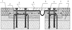
Fig. 1 is interdigitated electrode structure shrinkage joint sectional drawing; Fig. 2 is location tire schematic diagram; Fig. 3 locating rack front view schematic diagram, Fig. 4 are several locating rack schematic top plan view.Fig. 5 is movable hanging holding tool schematic diagram.
Among the figure, 1 bituminous concrete, 2 pre-buried type muscle, 3 little tooth plates, 4 large tooth plates, 5 water proof rubber bands, 6 anchor bolts, 7 C50 steel fibrous concretes, 8 C40 bridge deck pavements, 9 preformed holes, 10 bolts, 11 frameworks, 12 adjusting bolt group elevation screw rods, 13 nuts, 14 anchor plates, 15 flat boards, 16 cross bars, 17 road wheels, 18 vehicle frames, 19 strong electromagnets.
The specific embodiment
Accompanying drawing is a kind of specific embodiment of the present invention.
Mounting broach type expanssion joint construction process of the present invention may further comprise the steps: preparation of construction → abolish pitch → processing anchor bolt group → installation anchor bolt group → install inner formword → build comb plate below merchant's concrete → comb plate is installed (water proof rubber band, corrosion resistant plate) → build comb plate both sides merchant's concrete → maintenance → inspect for acceptance.
Technical indicator: shrinkage joint and superelevation of highway surface≤2mm, the adjacent fingers plate hight is poor≤2mm.Around the shrinkage joint without loose, crack, sedimentation, infiltration, during driving without jumping car, abnormal sound phenomenon.
Preparation of construction
1), check the quality of comb plate, C50 steel fiber concrete, corrosion resistant plate, water proof rubber band, anchor bolt to conform to quality requirements, to receiving inspections such as comb plate physical dimension, degree of agreements;
2), determine in advance the shrinkage joint sequence of construction according to construction condition, Road width, plant equipment ability etc.;
3), determine shrinkage joint installation planeness and the control point of antiseepage water-based and the foundation of inspecting for acceptance.
Abolish pitch
Determine to abolish the pitch width according to comb plate and shrinkage joint design width.According to designing requirement, abolish the wide comb plate 15cm of going out of the every side of pitch scope.Determine the center that the beam-ends reservation is stitched by central hard shoulder and anticollision barrier, determine two sidelines at shrinkage joint by the design width.The both sides, sideline are laid colour bar cloth and are prevented from abolishing the pollution flexible pavements such as waste residue powder that produce in the pitch process.
Cut out the dark slit of 1cm along the sideline with manual cast-cutting saw first, use again large-scale cast-cutting saw joint-cutting to case beam agent structure.Abolish pitch and clean out foreign material in the groove with pneumatic pick, the process of abolishing forbids to destroy slot bituminous sheaths in addition, asphalt slag is deposited into colour bar cloth supernatant transports to the appointment place.Beam-ends is reserved and is sewed on lower must the perforation, must not stop up.
Processing anchor bolt group
Comb plate is placed on the burnishing surface, placement positioning tire on the comb plate, place cushion block on the tire of location, cushion block height=rubber tile thickness+(corrosion resistant plate thickness)-location tire thickness-2mm, place the anchor plate corresponding with the hole of comb plate at cushion block, anchor bolt is passed the interdigitated electrode structure hole of hole, comb plate of hole, location tire of anchor plate to burnishing surface, anchor bolt is connected with the anchor plate electric welding, with three horizontal reinforcing bars that draw with four anchor plate vertical weldings formation anchor bolt groups.In welding process, must not make the anchor plate distortion.
By the location tire anchor bolt and anchor plate welding are formed the anchor bolt group, this procedure can be constructed in advance, not restricted by other operations.The location tire is take comb plate as the template "one off" production, and physical dimension and preformed hole position and comb plate coincide, and preformed hole position and comb plate, location tire coincide on the anchor plate.Adopting three-dimensional location carcass is that anchor plate and anchor bolt welding form the anchor bolt group, has guaranteed anchor bolt perpendicular to the anchor plate plane, and anchor bolt exposes the anchor plate pin-point accuracy.
The location tire comprises two parallel angle bar and is installed in two blocks of steel plates side by side between two angle bar, one block plate is fixed, another block plate is regulated the plan-position by the loose slot of reserving on the angle bar, and the preformed hole position is corresponding with the comb plate preformed hole on two block plates.Steel plate is installed on the angle bar by bolt.
The anchor bolt group is installed
Adopt special locating rack that the anchor bolt group is moved in the preformed groove, place respectively first one group of anchor bolt group at the two ends, shrinkage joint.Draw reference line along the preformed groove direction, the fixed datum two ends by two end unit bolt groups.Fine setting anchor bolt group makes the bolt upper end be lower than both sides bituminous sheaths 2mm, and the anchor bolt group is connected and firm welding with pre-buried door shape muscle.Along reference line, put into successively the anchor bolt group, adjust bolt position and height, the weld anchor fixing bolt, the anchor bolt location is finally finished in cycling.After finish anchor bolt location, put into successively water proof rubber band, corrosion resistant plate, interdigitated electrode structure and try to install, guarantee that anchor bolt penetrates the interdigitated electrode structure preformed hole smoothly, and be lower than interdigitated electrode structure surface 2-3mm.
Move in the groove and the embedded ribs firm welding the anchor bolt group is whole by special locating rack, guaranteed that the anchor plate plane is parallel with the both sides bituminous sheaths, anchor plate and the both sides pitch discrepancy in elevation is (discrepancy in elevation h=comb plate thickness+water proof rubber tape thickness-2mm) accurately, thereby guaranteed the pre-buried position of anchor bolt accurately and perpendicular to bituminous sheaths, both sides asphaltene formation degree meets designing requirement behind the mounting broach plate, has stopped the mass defects such as jumping car, abnormal sound.
Locating rack comprises three transverse frames and four vertical anchor plates, and be installed on the framework screw rod that is used for adjusting bolt group elevation, anchor plate is vertically welded in below the framework, and the screw rod upper end of adjusting bolt group elevation is equipped with adjusting nut, and the lower end is provided with the bending segment of suspention anchor bolt group.
During use, the bolt top of anchor bolt group upwards withstands on below the anchor plate of locating rack, the adjusting bolt group elevation screw rod of locating rack is moved up, make the bending segment of its lower end upwards withstand the anchor bolt group anchor plate below, then lock adjusting nut, again locating rack is put into groove with the anchor bolt group, three transverse frames ride on the pitch of both sides on the locating rack, thereby make anchor bolt group pin-point accuracy location, then anchor bolt bottom and the pre-buried door shape muscle with the anchor bolt group welds, adjusting nut with locating rack unclamps at last, and adjusting bolt group elevation screw rod 90-degree rotation can take out locating rack.So carry out again location and the installation of next anchor bolt group.
Install template
Before installing template, with rubbish in high-pressure blast (water) the rifle cleaning slot, particularly because of deck paving do not build the unsettled place of pitch that causes of putting in place draw dig clean.According to beam-ends gap formwork supporting plate, gap error ± 2 ㎜, the template height flushes with the comb plate bottom, and the stainless steel slide plate is arranged under the little tooth plate, and shrinkage joint two side template height are different.Fixed end tooth plate (little tooth plate) template end face is apart from bituminous sheaths distance=interdigitated electrode structure thickness+corrosion resistant plate thickness+rubber tile thickness=28mm+3mm+5mm=36mm, and movable end tooth plate (large tooth plate) template end face is apart from bituminous sheaths distance=interdigitated electrode structure thickness+rubber tile thickness=28mm+5mm=33mm.Inner formword must install firmly tight, prevents that concrete from stopping up the flexible slit of beam-ends.
Build a step merchant concrete
Build for the first time to comb template bottom surface, after the comb plate installation is reinforced and finished, build again comb plate outside concrete.For the second time discuss concrete thickness and be not less than 8cm for guaranteeing to build, when building first step concrete, steel wire lump is put in the comb plate outside, builds and takes out steel wire lump after finishing concrete initial set.Colour bar cloth is laid in the both sides, shrinkage joint during concreting, and trolley is walked at colour bar cloth, avoids concrete to pollute flexible pavement.Merchant's concrete must be built closely knit, smooth without honeycomb, and continuous placing, guarantees globality; First step merchant's concrete waters to the anchor plate plane, and comb plate outside concrete allows to be lower than the template end face, must plucking before the initial set, concrete adopts the method for vibrating, the dead angle of vibrating especially, to pulp, no longer include bubble till.Behind the vibration compacting, with floating rule concrete surface is struck off the flat or lower slightly 1-2mm of upper surface and template.
The mounting broach plate
1), before the rubber strip of mating formation, at the even blade coating 2-3mm of the concrete surface of building, striking off waterproofing mortar (this step is essential, effectively stops shrinkage joint infiltration phenomenon), the grit of projection must not be arranged.Bottom is smeared first plain mortar 3mm, smears the waterproofing mortar layer again, and compacting during initial set is twisted into pitted skin with wood float; Catch up with optical pressure real after smearing second layer waterproofing mortar.
2), the water proof rubber band of mating formation: check the water proof rubber band, have the cavity must not use without exception such as the aqua storage tank position.There are error in rubber cushion preformed hole and anchor bolt position, allow finishing.The phenomenons such as gauffer have not been allowed when laying the water proof rubber band; The mated condition of inspection rubber cushion preformed hole and bolt was filled up with encapsulant when the gap is larger after laying was finished.
3), lay corrosion resistant plate: check that corrosion resistant plate has or not burr etc., clear up smooth, cleaning water proof rubber belt surface, placement corrosion resistant plate.
4), need cleaning corrosion resistant plate surface before the mounting broach plate, with the corresponding placed comb tooth plate of lifting device, with spirit level comb plate is carried out straight degree and planeness detection in the installation process, comb plate end face and superelevation of highway surface are controlled at 0~2mm(and check with wedge-shaped feeler gauge), the adjacent comb type steel plate discrepancy in elevation is controlled at 2mm.At comb plate preformed hole built-in spring pad, screw nut with torque wrench, with the comb plate fixation.After reaffirming that installation is errorless, with fluid sealant bolt hole is filled and led up.
The mobile hoisting instrument comprises the vehicle frame that is installed on the road wheel, and the vehicle frame front end is connected with the strong electromagnet that positive and negative switch is controlled by hoisting rope, and strong electromagnet can adsorb the ganoid comb plate of carrying.
5), reserve 1 meter wide at the place, shrinkage joint when anticollision barrier, central hard shoulder pouring construction, 0.3 meter is high, 0.3 meter dark reserved opening, and 0.2 meter of anticollision barrier, central hard shoulder is goed deep at the shrinkage joint, and the adhesive waterproof tape perk is with the floating reserved opening of mortar.
Build two step merchant concretes
1), rubbish and with high-pressure blast (water) rifle cleaning in the cleaning groove, bituminous sheaths is pasted colour bar cloth with adhesive tape and is protected before the concreting, avoids concrete to pollute bituminous sheaths.
2), merchant's concrete must build closely knit, smoothly without honeycomb, and continuous placing guarantees globality, the concrete surface processing procedure divided for three steps: it is real to rub densification when building, and laitance is removed in the press polish of wiping one's face after the initial set after the final set.Concrete is higher than both sides bituminous sheaths 0-2mm behind the receipts face.
3), the waste materials such as concrete on colour bar cloth are trickled down in time cleaning.
Maintenance
In surface watering and covering gunnysack or geotextiles, curing time is not less than 7d behind the concrete initial set; Carry out traffic control by the special messenger between curing time, take protection or sealing measure.
Inspect for acceptance
When 2. stretching device is installed its gap value locator value by producer during according to construction temperature finish in factory, fix with locator card.Adjust location and fixing rear timely the installation.
6. the stretching device center line aligns with the intersegmental crack of beam center line and overlaps, and each point height of stretching device end face should be corresponding consistent with bridge floor cross section elevation.
The situation of having used and having promoted:
This engineering method is used in the rapid improvement project in outer shroud North Road, Nantong, river road, Tongyang Canal center, Nantong City Bridge Project, through designing unit, supervisor's onsite acceptance, the interdigitated electrode structure shrinkage joint is connected intact with road surface on every side, elevation is consistent, planeness meets the pavement of road acceptance criteria, guarantee the integral smoothness on road surface, reached the good result that the road surface is attractive in appearance, driving is comfortable.Wide application space is arranged in the installing engineering of interdigitated electrode structure shrinkage joint, promotional value is arranged.
Claims (4)
1. mounting broach type expanssion joint construction process is characterized in that: may further comprise the steps: comb plate both sides merchant's concrete → maintenance → inspect for acceptance is installed → built to preparation of construction → abolish pitch → processing anchor bolt group → installation anchor bolt group → install inner formword → build comb plate below merchant's concrete → comb plate;
Processing anchor bolt group step: comb plate is placed on the burnishing surface, placement positioning tire on the comb plate, place cushion block on the tire of location, place the anchor plate corresponding with the hole of comb plate at cushion block, anchor bolt is passed the hole of the hole of anchor plate, the hole of locating tire, comb plate to burnishing surface, anchor bolt is connected with the anchor plate electric welding, with three horizontal reinforcing bars that draw four anchor plate vertical weldings is formed the anchor bolt group;
Anchor bolt group step is installed: adopt locating rack that the anchor bolt group is moved in the preformed groove, place respectively first one group of anchor bolt group at the two ends, shrinkage joint, draw reference line by two end unit bolt groups along the preformed groove direction, the fixed datum two ends, fine setting anchor bolt group, make the bolt upper end be lower than both sides bituminous sheaths 2mm, the anchor bolt group is connected and firm welding with pre-buried door shape muscle, along reference line, put into successively the anchor bolt group, adjust bolt position and height, weld anchor fixing bolt, the anchor bolt location is finally finished in cycling; After finish anchor bolt location, put into successively water proof rubber band, corrosion resistant plate, interdigitated electrode structure and try to install, guarantee that anchor bolt is inserted in interdigitated electrode structure smoothly, and be lower than interdigitated electrode structure surface 3mm;
Comb plate installation steps: before the rubber strip of mating formation, at the even blade coating waterproofing mortar of the concrete surface of building, striking off, then the water proof rubber band of mating formation, lay corrosion resistant plate, with the corresponding placed comb tooth plate of movable hanging holding tool, comb plate end face and superelevation of highway surface are controlled at 0~2mm, check with wedge-shaped feeler gauge, and the adjacent comb type steel plate discrepancy in elevation is controlled at 2mm; At comb plate preformed hole built-in spring pad, screw nut with torque wrench, with the comb plate fixation, install errorless after, with fluid sealant bolt hole is filled and led up.
2. mounting broach type expanssion joint construction process movable hanging holding tool claimed in claim 1, it is characterized in that: the mobile hoisting instrument comprises the vehicle frame that is installed on the road wheel, the vehicle frame front end is connected with the strong electromagnet that positive and negative switch is controlled by hoisting rope, and strong electromagnet can adsorb the ganoid comb plate of carrying.
3. a mounting broach type expanssion joint construction process claimed in claim 1 is with locating tire, it is characterized in that: the location tire comprises two parallel angle bar and is installed in two blocks of steel plates side by side between two angle bar, one block plate is fixed, another block plate is regulated the plan-position by the loose slot of reserving on the angle bar, and the preformed hole position is corresponding with the comb plate preformed hole on two block plates.
4. mounting broach type expanssion joint construction process locating rack claimed in claim 1, it is characterized in that: locating rack comprises three transverse frames and four vertical anchor plates, and be installed on the framework screw rod that is used for adjusting bolt group elevation, anchor plate is vertically welded in below the framework, the screw rod upper end of adjusting bolt group elevation is equipped with adjusting nut, and the lower end is provided with the bending segment of suspention anchor bolt group.
Priority Applications (1)
| Application Number | Priority Date | Filing Date | Title |
|---|---|---|---|
| CN201210436002.6A CN102926322B (en) | 2012-11-06 | 2012-11-06 | Construction method, hoisting tool, location tire and location support for installing comb-tooth-shaped expansion joint |
Applications Claiming Priority (1)
| Application Number | Priority Date | Filing Date | Title |
|---|---|---|---|
| CN201210436002.6A CN102926322B (en) | 2012-11-06 | 2012-11-06 | Construction method, hoisting tool, location tire and location support for installing comb-tooth-shaped expansion joint |
Publications (2)
| Publication Number | Publication Date |
|---|---|
| CN102926322A true CN102926322A (en) | 2013-02-13 |
| CN102926322B CN102926322B (en) | 2015-07-15 |
Family
ID=47641239
Family Applications (1)
| Application Number | Title | Priority Date | Filing Date |
|---|---|---|---|
| CN201210436002.6A Active CN102926322B (en) | 2012-11-06 | 2012-11-06 | Construction method, hoisting tool, location tire and location support for installing comb-tooth-shaped expansion joint |
Country Status (1)
| Country | Link |
|---|---|
| CN (1) | CN102926322B (en) |
Cited By (4)
| Publication number | Priority date | Publication date | Assignee | Title |
|---|---|---|---|---|
| CN105951598A (en) * | 2016-05-19 | 2016-09-21 | 重庆巨能建设集团路桥工程有限公司 | Installation locator for bridge prestress type multidirectional deflection telescopic device |
| CN108468271A (en) * | 2018-04-12 | 2018-08-31 | 北京鼎翰科技有限公司 | Bridge extension joint positioning tool |
| CN110777650A (en) * | 2019-11-29 | 2020-02-11 | 中建三局第二建设工程有限责任公司 | Embedded assembly type expansion joint overlength installation suspension leveling positioning system and construction method |
| CN115679808A (en) * | 2022-11-07 | 2023-02-03 | 上海市政养护管理有限公司 | Comb plate expansion joint anti-loosening structure and construction method |
Citations (10)
| Publication number | Priority date | Publication date | Assignee | Title |
|---|---|---|---|---|
| KR100712013B1 (en) * | 2007-01-19 | 2007-04-27 | 림버스산업 주식회사 | Expansion joint without block-out and its construction method |
| WO2007125556A1 (en) * | 2006-05-03 | 2007-11-08 | Atg S.R.L. | Expansion joint for pavement items and related manufacturing and assembling method |
| CN201473884U (en) * | 2009-09-01 | 2010-05-19 | 董淑练 | Vibrationless expansion joint for highway bridge |
| CN201635003U (en) * | 2009-12-19 | 2010-11-17 | 柳州东方工程橡胶制品有限公司 | Prestressed type multi-way shift comb-shaped plate expansion device |
| CN201678943U (en) * | 2010-05-31 | 2010-12-22 | 许昌义 | Comb-type expansion joint device with keys |
| CN101985824A (en) * | 2010-08-23 | 2011-03-16 | 重庆城建控股(集团)有限责任公司 | Embedded part mounting device for bridge bearing |
| CN102102340A (en) * | 2010-12-28 | 2011-06-22 | 河北路桥集团有限公司 | Bridge expansion and contraction device and installation method thereof |
| CN202227265U (en) * | 2011-09-29 | 2012-05-23 | 衡水橡胶股份有限公司 | Comb tooth type bridge retracting device |
| CN102518036A (en) * | 2011-10-31 | 2012-06-27 | 中交一航局第四工程有限公司 | Construction method for installing bridge expansion joint |
| CN102756988A (en) * | 2012-07-09 | 2012-10-31 | 江苏省交通工程集团有限公司 | Movable sling for mounting expansion joint of comb plate |
-
2012
- 2012-11-06 CN CN201210436002.6A patent/CN102926322B/en active Active
Patent Citations (10)
| Publication number | Priority date | Publication date | Assignee | Title |
|---|---|---|---|---|
| WO2007125556A1 (en) * | 2006-05-03 | 2007-11-08 | Atg S.R.L. | Expansion joint for pavement items and related manufacturing and assembling method |
| KR100712013B1 (en) * | 2007-01-19 | 2007-04-27 | 림버스산업 주식회사 | Expansion joint without block-out and its construction method |
| CN201473884U (en) * | 2009-09-01 | 2010-05-19 | 董淑练 | Vibrationless expansion joint for highway bridge |
| CN201635003U (en) * | 2009-12-19 | 2010-11-17 | 柳州东方工程橡胶制品有限公司 | Prestressed type multi-way shift comb-shaped plate expansion device |
| CN201678943U (en) * | 2010-05-31 | 2010-12-22 | 许昌义 | Comb-type expansion joint device with keys |
| CN101985824A (en) * | 2010-08-23 | 2011-03-16 | 重庆城建控股(集团)有限责任公司 | Embedded part mounting device for bridge bearing |
| CN102102340A (en) * | 2010-12-28 | 2011-06-22 | 河北路桥集团有限公司 | Bridge expansion and contraction device and installation method thereof |
| CN202227265U (en) * | 2011-09-29 | 2012-05-23 | 衡水橡胶股份有限公司 | Comb tooth type bridge retracting device |
| CN102518036A (en) * | 2011-10-31 | 2012-06-27 | 中交一航局第四工程有限公司 | Construction method for installing bridge expansion joint |
| CN102756988A (en) * | 2012-07-09 | 2012-10-31 | 江苏省交通工程集团有限公司 | Movable sling for mounting expansion joint of comb plate |
Non-Patent Citations (1)
| Title |
|---|
| 王辉等: "梳齿型伸缩缝安装工艺及质量控制", 《市政技术》, no. 1, 10 May 2012 (2012-05-10) * |
Cited By (6)
| Publication number | Priority date | Publication date | Assignee | Title |
|---|---|---|---|---|
| CN105951598A (en) * | 2016-05-19 | 2016-09-21 | 重庆巨能建设集团路桥工程有限公司 | Installation locator for bridge prestress type multidirectional deflection telescopic device |
| CN108468271A (en) * | 2018-04-12 | 2018-08-31 | 北京鼎翰科技有限公司 | Bridge extension joint positioning tool |
| CN108468271B (en) * | 2018-04-12 | 2019-07-02 | 北京鼎翰科技有限公司 | Bridge extension joint positioning tool |
| CN110777650A (en) * | 2019-11-29 | 2020-02-11 | 中建三局第二建设工程有限责任公司 | Embedded assembly type expansion joint overlength installation suspension leveling positioning system and construction method |
| CN110777650B (en) * | 2019-11-29 | 2024-08-20 | 中建三局第二建设工程有限责任公司 | Pre-buried assembly type expansion joint overlength installation suspension leveling positioning system and construction method |
| CN115679808A (en) * | 2022-11-07 | 2023-02-03 | 上海市政养护管理有限公司 | Comb plate expansion joint anti-loosening structure and construction method |
Also Published As
| Publication number | Publication date |
|---|---|
| CN102926322B (en) | 2015-07-15 |
Similar Documents
| Publication | Publication Date | Title |
|---|---|---|
| CN101906768B (en) | Panel construction method of concrete faced rock-fill dam | |
| CN103669114B (en) | Ballast bed base prefabricated slab and application thereof | |
| CN101195983B (en) | Unballasted track bed plate construction method | |
| CN108638324A (en) | A kind of construction method of prefabricated case beam | |
| CN107974935A (en) | A kind of SF combs flute profile telescopic device and its construction method of installation | |
| CN103233424A (en) | Hanging-basket-method support-free anti-collision wall construction method, construction hanging basket and template for construction | |
| CN113250050B (en) | A technical method for airport pavement assembly replacement plate replacement | |
| CN102966037A (en) | Installation and construction process of bridge expansion joints | |
| CN104452581B (en) | A kind of cantilever base spiral shell anchor formula comb plate stretching device | |
| CN104131498A (en) | Lifting repair method for ballastless track with settled curved section | |
| CN104372890A (en) | Construction method of bare concrete prefabricated box beam with complicated structure | |
| CN102926322B (en) | Construction method, hoisting tool, location tire and location support for installing comb-tooth-shaped expansion joint | |
| CN108239990A (en) | A construction method using secondary pouring for street lamp foundation | |
| CN103233482B (en) | Cable trench pre-embedded bolt construction method of installation | |
| CN203174510U (en) | Movable assembly type hanging basket for bridge anti-collision guardrail construction and formwork for construction | |
| CN108342993A (en) | A kind of underwater support table suspention support platform and its construction | |
| CN203174497U (en) | Positioning frame for installation construction of comb type expansion joints | |
| CN110965409A (en) | Sleeper shoulder-blocking repairing technology | |
| CN203174496U (en) | Positioning tire for installation construction of comb type expansion joints | |
| CN101906757A (en) | Assembly method for replacing plate type rubber support on abutment of highway bridge | |
| CN102587252A (en) | Wavy high-precision curve cement concrete pavement construction method | |
| CN203049448U (en) | Hoisting tool, positioning tire and positioning frame for mounting comb-tooth-shaped expansion joint construction | |
| CN109267580B (en) | Concrete steel bar composite structure and pouring method | |
| CN209066480U (en) | A kind of precast hollow module block type concrete retaining wall | |
| CN204781252U (en) | Can cross escape canal of heavy vehicle and apron thereof |
Legal Events
| Date | Code | Title | Description |
|---|---|---|---|
| C06 | Publication | ||
| PB01 | Publication | ||
| C10 | Entry into substantive examination | ||
| SE01 | Entry into force of request for substantive examination | ||
| C14 | Grant of patent or utility model | ||
| GR01 | Patent grant |