CN102995281A - Knitting tool holder - Google Patents
Knitting tool holder Download PDFInfo
- Publication number
- CN102995281A CN102995281A CN2011104293116A CN201110429311A CN102995281A CN 102995281 A CN102995281 A CN 102995281A CN 2011104293116 A CN2011104293116 A CN 2011104293116A CN 201110429311 A CN201110429311 A CN 201110429311A CN 102995281 A CN102995281 A CN 102995281A
- Authority
- CN
- China
- Prior art keywords
- braiding
- cover plate
- tool support
- instrument
- braiding tool
- Prior art date
- Legal status (The legal status is an assumption and is not a legal conclusion. Google has not performed a legal analysis and makes no representation as to the accuracy of the status listed.)
- Granted
Links
Images


Classifications
-
- D—TEXTILES; PAPER
- D04—BRAIDING; LACE-MAKING; KNITTING; TRIMMINGS; NON-WOVEN FABRICS
- D04B—KNITTING
- D04B27/00—Details of, or auxiliary devices incorporated in, warp knitting machines, restricted to machines of this kind
- D04B27/02—Warp-thread guides
-
- D—TEXTILES; PAPER
- D04—BRAIDING; LACE-MAKING; KNITTING; TRIMMINGS; NON-WOVEN FABRICS
- D04B—KNITTING
- D04B27/00—Details of, or auxiliary devices incorporated in, warp knitting machines, restricted to machines of this kind
- D04B27/06—Needle bars; Sinker bars
-
- D—TEXTILES; PAPER
- D04—BRAIDING; LACE-MAKING; KNITTING; TRIMMINGS; NON-WOVEN FABRICS
- D04B—KNITTING
- D04B27/00—Details of, or auxiliary devices incorporated in, warp knitting machines, restricted to machines of this kind
- D04B27/10—Devices for supplying, feeding, or guiding threads to needles
-
- D—TEXTILES; PAPER
- D04—BRAIDING; LACE-MAKING; KNITTING; TRIMMINGS; NON-WOVEN FABRICS
- D04B—KNITTING
- D04B27/00—Details of, or auxiliary devices incorporated in, warp knitting machines, restricted to machines of this kind
- D04B27/10—Devices for supplying, feeding, or guiding threads to needles
- D04B27/24—Thread guide bar assemblies
Landscapes
- Engineering & Computer Science (AREA)
- Textile Engineering (AREA)
- Knitting Machines (AREA)
- Piles And Underground Anchors (AREA)
- Fencing (AREA)
Abstract
The tool holder (1) has a spacer (13) made from light metal or plastic, which is arranged between steel or plastic made cover plates (8,9) each with a thickness of about 0.1-0.8 mm. The knitting tools (2) are arranged parallel to each other with a predetermined distance. The front and rear narrow sides (4,5) of the knitting tools are bonded to the respective cover plates (8,9) through adhesive (12).
Description
Technical field
The present invention relates to a kind of braiding tool support, with a plurality of braiding instruments, each braiding instrument has workspace, fixed area and two narrow sides of pointing in opposite direction, and wherein, the braiding instrument is arranged to spacing side by side parallel to each other and that the space is predetermined.
Background technology
Usually in braiding machine generally, with a plurality of braiding instruments concentrate on one the braiding tool support in.The braiding tool support often has the width of one or two inch (Zoll), and admits the braiding instrument of respective numbers according to precision.
The concept of " braiding instrument " referred to herein as the especially abbreviation of those elements of participation knitting cycle when producing braided fabric of warp knitting machine of braiding machine.The braiding instrument not only relates to original braiding instrument such as knitting needle, slide block, sinker etc., also relates to thread-guide element, if any eye pin, pectination press strip (Kammplatine) etc.
When a plurality of braiding instruments were assembled one group in carriage, these braiding instruments can obtain faster install and adjust at braiding machine.
Initial people cast the braiding instrument in order to produce carriage with lead.The defective of doing like this is to be accompanied by very large quality, and this can have a negative impact to the operating rate of braiding machine.The temperature that occurs in when casting also can allow the braiding tool variations, and this is so that necessitate to the post processing of wasting time and energy of braiding tool support.
In DE 10 2,009 010 316 A1, advise, cast the braiding instrument with plastics.
DE 196 18 368 B4 have described a kind of braiding tool support, and with support, support has groove.Groove is filled with the filler that can harden, and when filler is also unhardened the braiding instrument is placed filler.
In the machine of fast operation, not only weave tool bar, and the braiding tool support, all must have very high rigidity and enough intensity.This can cause the wall thickness of braiding tool support larger when using for the former thereby preferred plastics of weight or light metal.This causes again the quality of not expecting occurring giving birth to and improves.In addition, people for example are subject to sley point (Legenadeln) when selecting guide, because yarn should not bump against with the braiding tool support.
Summary of the invention
Technical problem to be solved by this invention is, a kind of braiding tool support is provided, and it only needs very little structure space when rigidity is very large.
Start in the braiding tool support of described type at this paper, this technical problem solves thus, that is, the braiding instrument is arranged between two cover plates, and wherein, narrow side and cover plate are bonding.
Use this design, only adhesives just can couple together braiding instrument and braiding tool support on a small quantity.This amount only must be set up the connection between the narrow side of braiding instrument and cover plate.When mounted, the braiding instrument is arranged side by side with desired calibration and for example locates by corresponding standard.Then adhesives can be coated on the narrow side of braiding instrument or be coated on the side of cover plate, then that cover plate and braiding instrument is bonding.Then the narrow side at other repeats identical process.Certainly, these two bonding process also can carry out simultaneously.Then form a kind of sandwich composite construction that is consisted of by two cover plates and braiding instrument.Surprisingly, bonding on narrow side of braiding instrument is enough to provide a kind of braiding tool support, this braiding tool support to have very little quality and under any circumstance all has enough rigidity after the braiding tool support is fixed on the corresponding braiding tool bar.
Each braiding instrument preferably has rod member and cover plate in FX and this rod member is bonding.Therefore createed the contact area that limits at the braiding instrument for cover plate.This has simplified manufacturing.
Rod member preferably has projection at least one narrow side, and projection exceeds giving prominence to of cover plate distolaterally, and wherein, projection has and described distolateral bonding abutment face.Projection can be configured to only hide the part of distolateral thickness, thereby produces corresponding less bonding plane.But projection also can be constructed greatly to making abutment face have the same with distolateral extension at least large extension.In this case, carry out on the bonding surface that is connected to maximum possible.Then the braiding instrument can be said to a certain extent towards two different directions and remain in the braiding tool support.Improved thus stability.Simplify in addition installation, defined a position because give prominence to, on this position, can touch cover plate.
Projection is preferably surrounded cover plate outside, and wherein, projection is bonding with cover plate on the outside of cover plate.In other words, projection has the groove that is slightly larger than cover sheet thickness.Then cover plate is imported in this groove, thereby makes braiding instrument U-shaped ground in the zone of projection surround cover plate.Therefore provide three bonding planes in each braiding instrument between braiding instrument and cover plate, this has produced high stability.
Preferred arrangement interval part between cover plate, distance piece has thickness, the spacing between the narrow side of this thickness correspondence in braiding instrument FX.Cover plate links to each other with distance piece, and is for example same by bonding.Therefore cover plate not only is fixed on the braiding instrument, also is fixed on the distance piece, and cover plate can abut on the distance piece by plane earth.This makes the braiding tool support have high stability.
Distance piece preferably terminates in of rod member on the end of working region.Zone between the braiding instrument does not have to fill by adapter arbitrarily or by the element of distance piece.Especially when very high, can make more simply distance piece be equipped with the lateral margin of not moulding in the precision of braiding instrument, lateral margin is not charged into the gap between the braiding instrument.
Distance piece preferably is made of light metal or plastics.Therefore because the quality that distance piece brings change can remain on greatly very little.
Distance piece preferably consists of at least one backstop.In the time will weaving tool support and be installed on the braiding tool bar, backstop plays help in when location.
Stipulate in the preferred design of the first, cover plate is passed in the backstop guiding.But be necessary that in this case, for cover plate sets corresponding hole.But the advantage of this design is, also can with distance piece and cover plate form fit interconnect, this has further improved the stability of braiding tool support.
In the preferred design of the second, backstop is being stretched out from the space between the cover plate on that side of braiding instrument.In this case, distance piece has been configured to more simple profile.
In FX, the spacing between the narrow side is preferably less than the thickness sum of cover plate.Therefore the physical dimension that weaves tool support keeps very littlely.In fact cover plate can not cause physical dimension significantly to become large.
Cover plate is preferably made by the face shaped material of thickness in 0.1 to 0.8 mm scope.Cover plate in fact also can be configured to film.Although cover plate is very thin, also can be based on guaranteeing enough stability with bonding connection of braiding instrument.
At this preferably, the face shaped material is steel or plastics, uses according to circumstances fibre strengthening.The face shaped material must only have enough tensile strength, in order to can resist stress when braiding machine moves.
The braiding instrument preferably stretches out from cover plate and is 10 mm to the maximum.Therefore braiding machine only has shorter drift, and they can be out of shape in this drift.This expense during on the one hand with post processing remains on very little, for example when calibration braiding instrument.On the other hand, the stress of the bonding connection between braiding instrument and the cover plate is less, because only shorter lever arm is available.
The braiding tool support is preferably configured as about the plane symmetry between the cover plate.When the braiding tool support is installed, needn't pay close attention to the particular orientation that the braiding tool support weaves tool support relatively.
Description of drawings
Next by preferred embodiment and be described with reference to the accompanying drawings the present invention.In the accompanying drawing:
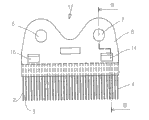
Fig. 1 is the front view of braiding tool support;
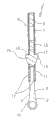
Fig. 2 shows the section B-B by Fig. 1;
Fig. 3 is the stereogram of embodiment after a kind of modification of braiding tool support;
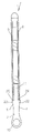
Fig. 4 is the schematic cross sectional views by the braiding tool support of Fig. 3;
Fig. 5 shows the form of implementation after a kind of relative Fig. 4 modification; And
Fig. 6 has illustrated form of implementation after a kind of relative Fig. 5 modification with profile.
The specific embodiment
Fig. 1 shows the braiding tool support 1 with a plurality of braiding instruments 2, the braiding instrument 2 preset space length 3 ground settings of being separated by side by side and to each other.Braiding instrument 2 only can be seen narrow side 4 in Fig. 1.When will visible narrow side 4 is appointed as the front in Fig. 1, so corresponding narrow side 5 be located on the back side. Narrow side 4,5 fingers are in the opposite direction.
By Fig. 2 and 3 as can be known, constructed by plane earth with the braiding instrument 2 that an aciculiform formula is arranged exists at this.They can be for example with there being the sheet metal punching of respective thickness to form.
The braiding tool support has two eyes 6,7, and bolt can be guided and be passed this two eyes, and braiding tool support 1 can be fixed by bolts on the braiding tool bar that is not shown specifically.It for example is 1 or 2 inch width that braiding tool support 1 has.Because eye 6,7 can be arranged as away from must be mutually, so braiding tool support 1 has good directed possibility at the braiding tool bar.
As especially can seeing among Fig. 2 and Fig. 3, braiding tool support 1 is configured to sandwich structure.The first cover plate 8 is bonding with the front narrow side 4 of braiding instrument 2.Narrow side 5 on the back side of the second cover plate 9 and braiding instrument is bonding.The address at " front " and " back side " is only explained in order to simplify in this use.Braiding tool support 1 is configured to and the plane symmetry between two cover plates 8,9, can be towards illustrated direction or towards installing with the direction of 180 ° of direction as shown deflections.
Braiding instrument 2 has working region 10 and FX, and FX is made of rod member 11 at this. Cover plate 8,9 is only bonding with braiding instrument 2 in the zone of rod member 11.For this reason, between rod member 11 and cover plate 8,9, arrange respectively adhesives 12.
In addition, between two cover plates 8,9, also be furnished with distance piece 13.Distance piece 13 has the thickness corresponding with the spacing in the zone of rod member 11 that is in FX between two narrow sides 4,5.Correspondingly with it is that two cover plates 8,9 can be constructed on their whole development length flatly. Cover plate 8,9 is connected with distance piece 13 plane earths, for example by bonding.But they also can be put and in succession a little or the line line ground of ining succession is connected with distance piece 13.
In pressing the design of Fig. 1 and 2, distance piece 13 has a pair of backstop 14,15, that is the backstop on the front 14 and the backstop 15 that goes up overleaf.And another is to seeing in the drawings the backstop of one of them backstop 16 on the front, can be arranged in the zone at other edge that weaves tool support 1.The corresponding hole 17,18 in the cover plate 8,9 is passed in backstop 14,15 guidings.They have facilitated the form fit between distance piece 13 and the cover plate 8,9.
Can see in Fig. 2, adhesives 12 is roughly given prominence to exceeding braiding instrument 2 ground between the inherent cover plate 8,9.This all is inevitably under many circumstances, but optional in principle.Can for example set up thus cover plate 8,9 and braiding instrument 2 between bonding connection, that is, braiding instrument 2 is arranged side by side abreast with desired calibration in corresponding standard and cover plate 8 is equipped with adhesive film (or another kind of adhesives).When cover plate 8 being lain in the braiding instrument and lying on the distance piece 13, can form desired bonding connection.Need in case of necessity to apply certain pressure.Can repeat identical way at cover plate 9.
Fig. 3 shows the design after a kind of modification, and the difference of the design of it and Fig. 1 and 2 is, distance piece 13 has backstop 19,20, and backstop is being stretched out from the space between cover plate 8,9 on the side of braiding instrument.In addition, element identical or that correspond to each other marks with identical Reference numeral.
Braiding tool support 1 by Fig. 3 also has material hollow out 21, in order to alleviate quality.
Fig. 4 shows the side view by the braiding tool support 1 of Fig. 3.
Fig. 5 shows a kind of flexible program by the braiding instrument 1 of Fig. 4.The end that faces working region 10 of the rod member 11 of braiding instrument 2 on positive 4 has projection 22, then has projection 23 on 5 overleaf.Projection 22,23 forms respectively abutment face 24,25. Abutment face 24,25 has from positive 45 the extensions to the back side, and this extension is greater than cover plate 8,9 thickness.Therefore also can in abutment face 24,25 zone, will weave instrument 2 and cover plate 8,9 distolateral being bonded together.Obtain thus the bonding connection on two different directions, that is along the longitudinal extension direction of braiding instrument 2 and transverse to this longitudinal extension direction.This is so that intensity improves, and rigidity improves.
Fig. 6 shows the form of implementation after the relative Fig. 5 modification that weaves tool support 1 with side view.
As seen from the figure, the projection 22,23 of braiding instrument 2 respectively has a groove 26,27, so projection 22,23 can be surrounded cover plate 8,9 in U-shaped ground.Groove 26,27 is constructed to be permeable to make cover plate 8,9 to import with very little gap.This gap greatly to make the people adhesives can also be inserted cover plate 8,9 and groove 26,27 wall between, thereby make braiding instrument 2 can with cover plate 8,9 bonding along groove 26,27 wall.
As mentioned above, cover plate 8,9 is very thin.In FX, that is on rod member 11, the spacing between the narrow side 4,5 is greater than cover plate 8,9 thickness sum.Correspondingly, the thickness of braiding tool support 1 is mainly determined by the width of braiding instrument.Cover plate 8,9 counts thickness hardly. Cover plate 8,9 can not be thicker than braiding instrument 2.
Claims (15)
1. braiding tool support, with a plurality of braiding instruments (2), each braiding instrument has working region (10), FX and two narrow sides (4,5) of pointing in the opposite direction, wherein weave instrument (2) to each other side by side parallel the and predetermined spacing of being separated by arrange (3), it is characterized in that, braiding instrument (2) is arranged between two cover plates (8,9), and wherein, narrow side (4,5) is bonding with cover plate (8,9).
2. by braiding tool support claimed in claim 1, it is characterized in that, each braiding instrument (2) has rod member (11) in FX and cover plate (8,9) is bonding with this rod member (11).
3. by braiding tool support claimed in claim 2, it is characterized in that, described rod member (11) has projection (22,23) at least one narrow side (4,5), projection (22,23) exceeds giving prominence to of cover plate (8,9) distolaterally, wherein, projection (22,23) has abutment face (24,25), and abutment face (24,25) is distolateral bonding with cover plate.
4. by braiding tool support claimed in claim 3, it is characterized in that, described projection (22,23) is externally surrounded cover plate (8,9), and wherein said projection (22,23) is bonding with cover plate (8,9) on the outside of cover plate (8,9).
5. by one of claim 1 to 4 described braiding tool support, it is characterized in that, arrangement interval part (13) between cover plate (8,9), distance piece (13) have with narrow side (4,5) in the FX of braiding instrument between thickness corresponding to spacing.
6. by braiding tool support claimed in claim 5, it is characterized in that, distance piece (13) terminates in the end of (10) back to the working region of rod member (11).
7. by claim 5 or 6 described braiding tool supports, it is characterized in that, distance piece (13) consists of by light metal or by plastics.
8. by one of claim 5 to 7 described braiding tool support, it is characterized in that, distance piece (13) has at least one backstop (14,15,19,20).
9. by braiding tool support claimed in claim 8, it is characterized in that, cover plate (8,9) is passed in backstop (14,15) guiding.
10. by braiding tool support claimed in claim 8, it is characterized in that, backstop (19,20) is being stretched out from the space between the cover plate (8,9) on the side of braiding instrument (2).
11. by one of claim 1 to 10 described braiding tool support, it is characterized in that, the spacing in the working region between narrow side (4,5) is greater than the thickness sum of cover plate (8,9).
12. by one of claim 1 to 11 described braiding tool support, it is characterized in that, cover plate (8,9) is made of the face shaped material of thickness in 0.1 to 0.8 mm scope.
13. by the described braiding tool support of claim 12, it is characterized in that, the face shaped material is steel or plastics, uses according to circumstances fibre strengthening.
14. by one of claim 1 to 13 described braiding tool support, it is characterized in that, braiding instrument (2) is maximum to stretch out 10 mm from cover plate (8,9).
15. by one of claim 1 to 14 described braiding tool support, it is characterized in that, this braiding instrument pedestal configurations becomes about the plane symmetry between the cover plate (8,9).
Applications Claiming Priority (2)
| Application Number | Priority Date | Filing Date | Title |
|---|---|---|---|
| EP11007549.6 | 2011-09-16 | ||
| EP20110007549 EP2570540B1 (en) | 2011-09-16 | 2011-09-16 | Functional tool mounting |
Publications (2)
| Publication Number | Publication Date |
|---|---|
| CN102995281A true CN102995281A (en) | 2013-03-27 |
| CN102995281B CN102995281B (en) | 2015-05-20 |
Family
ID=44785117
Family Applications (1)
| Application Number | Title | Priority Date | Filing Date |
|---|---|---|---|
| CN201110429311.6A Expired - Fee Related CN102995281B (en) | 2011-09-16 | 2011-12-20 | Knitting tool holder |
Country Status (2)
| Country | Link |
|---|---|
| EP (1) | EP2570540B1 (en) |
| CN (1) | CN102995281B (en) |
Cited By (2)
| Publication number | Priority date | Publication date | Assignee | Title |
|---|---|---|---|---|
| KR20200000348A (en) * | 2018-06-22 | 2020-01-02 | 칼 마이어 텍스틸마쉰넨파브릭 게엠베하 | Knitting tool mount |
| CN111247282A (en) * | 2017-07-17 | 2020-06-05 | 格罗兹-贝克特公司 | Tool module for textile machines |
Families Citing this family (1)
| Publication number | Priority date | Publication date | Assignee | Title |
|---|---|---|---|---|
| EP3581691B1 (en) | 2019-06-13 | 2023-03-08 | KARL MAYER STOLL R&D GmbH | Knitting tool and knitting machine |
Citations (5)
| Publication number | Priority date | Publication date | Assignee | Title |
|---|---|---|---|---|
| DE4438061C1 (en) * | 1994-10-25 | 1995-12-14 | Heguplast V Gutwald Kg Kunstst | Knitting machine bar segments are mfd. speedily, simply and accurately |
| CN1050869C (en) * | 1994-06-18 | 2000-03-29 | 卡尔迈尔纺织机械制造股份有限公司 | Needle mounting device for warp knitting machines 21678/01 |
| CN1069358C (en) * | 1996-05-08 | 2001-08-08 | 卡尔迈尔纺织机械制造有限公司 | Arrangement comprising thread guide elements for warp knitting or circular knitting machine and carrier |
| EP2048271A1 (en) * | 2007-10-13 | 2009-04-15 | Karl Mayer Textilmaschinenfabrik GmbH | Knitting tool assembly and knitting tool composite |
| CN100491616C (en) * | 2003-10-20 | 2009-05-27 | 利巴机械制造有限公司 | Frame needle bar for knitting frame, especially tricot machine |
Family Cites Families (3)
| Publication number | Priority date | Publication date | Assignee | Title |
|---|---|---|---|---|
| DE667602C (en) * | 1937-04-15 | 1938-11-15 | Ernst Liebers Fa | Hole needle arrangement for warp knitting machines |
| DE19803474C1 (en) * | 1998-01-29 | 1999-09-23 | Saxonia Umformtechnik Gmbh | Method of making comb-like structures |
| DE102009010316B4 (en) | 2009-02-24 | 2016-11-10 | Karl Mayer Textilmaschinenfabrik Gmbh | Method for producing a knitting tool holder |
-
2011
- 2011-09-16 EP EP20110007549 patent/EP2570540B1/en not_active Not-in-force
- 2011-12-20 CN CN201110429311.6A patent/CN102995281B/en not_active Expired - Fee Related
Patent Citations (5)
| Publication number | Priority date | Publication date | Assignee | Title |
|---|---|---|---|---|
| CN1050869C (en) * | 1994-06-18 | 2000-03-29 | 卡尔迈尔纺织机械制造股份有限公司 | Needle mounting device for warp knitting machines 21678/01 |
| DE4438061C1 (en) * | 1994-10-25 | 1995-12-14 | Heguplast V Gutwald Kg Kunstst | Knitting machine bar segments are mfd. speedily, simply and accurately |
| CN1069358C (en) * | 1996-05-08 | 2001-08-08 | 卡尔迈尔纺织机械制造有限公司 | Arrangement comprising thread guide elements for warp knitting or circular knitting machine and carrier |
| CN100491616C (en) * | 2003-10-20 | 2009-05-27 | 利巴机械制造有限公司 | Frame needle bar for knitting frame, especially tricot machine |
| EP2048271A1 (en) * | 2007-10-13 | 2009-04-15 | Karl Mayer Textilmaschinenfabrik GmbH | Knitting tool assembly and knitting tool composite |
Cited By (4)
| Publication number | Priority date | Publication date | Assignee | Title |
|---|---|---|---|---|
| CN111247282A (en) * | 2017-07-17 | 2020-06-05 | 格罗兹-贝克特公司 | Tool module for textile machines |
| KR20200000348A (en) * | 2018-06-22 | 2020-01-02 | 칼 마이어 텍스틸마쉰넨파브릭 게엠베하 | Knitting tool mount |
| KR102223592B1 (en) * | 2018-06-22 | 2021-03-05 | 칼 마이어 알앤디 게엠베하 | An arrangement of knitting tool mounts |
| TWI780330B (en) * | 2018-06-22 | 2022-10-11 | 德商卡爾邁耶斯托爾研發有限公司 | Arrangement of knitting tool mounts and method for assembling the same |
Also Published As
| Publication number | Publication date |
|---|---|
| CN102995281B (en) | 2015-05-20 |
| EP2570540A1 (en) | 2013-03-20 |
| EP2570540B1 (en) | 2014-03-05 |
Similar Documents
| Publication | Publication Date | Title |
|---|---|---|
| DE502005002224D1 (en) | Printed circuit board and method for its production | |
| ITBS20080219A1 (en) | JACQUARD HEADBAND BAR FOR TEXTILE MACHINES FOR KNITWEAR IN CHAIN | |
| CN102995281A (en) | Knitting tool holder | |
| ATE495293T1 (en) | WEAVE PATTERN FOR THE BODY-WORN SIDE OF A COMPOSITE MOLDED FIBER | |
| MY204577A (en) | Spunbonded non-woven fabric, method of manufacturing spunbonded non-woven fabric, and embossing roll | |
| CN105155103B (en) | A kind of reciprocating automatic wide cut carbon fiber braider | |
| MY143291A (en) | Procedure for manufacturing ladderproof fabrics | |
| CN114808263B (en) | A weft laying mechanism and a weft laying machine including the same | |
| BRPI0603998A (en) | warp knitting crochet gallon machine | |
| CN201901753U (en) | Special-space yarn separating device | |
| CN211256245U (en) | Piezoelectric jacquard device of warp knitting machine | |
| CN211665336U (en) | Embedding and clamping device for sewing | |
| CN202225414U (en) | Pultruded radome tooling | |
| CN207632972U (en) | A kind of creel of knitting machine | |
| CN204550966U (en) | The needle-bar of warp knitting machine | |
| CN215668414U (en) | Needle bed mechanism of double needle bed warp knitting machine | |
| CN203546302U (en) | Preset tension adjustment device for warping machine | |
| CN216235353U (en) | Fibrous tension adjusting device | |
| CN204151508U (en) | A kind of combined type is sold | |
| CN202786682U (en) | Warp knitting machine cloth full-width support cloth | |
| CN202415890U (en) | Yarn splitting device for glass fibers | |
| CN203229732U (en) | Flower combing needle fixing device | |
| CN102704204A (en) | Presser foot for double needle machine | |
| CN202519401U (en) | Adjustable square timber of brocade weaving machine | |
| CN101476178B (en) | Feed plate for a fiber processing textile machine |
Legal Events
| Date | Code | Title | Description |
|---|---|---|---|
| C06 | Publication | ||
| PB01 | Publication | ||
| C10 | Entry into substantive examination | ||
| SE01 | Entry into force of request for substantive examination | ||
| C14 | Grant of patent or utility model | ||
| GR01 | Patent grant | ||
| CF01 | Termination of patent right due to non-payment of annual fee |
Granted publication date: 20150520 Termination date: 20191220 |
|
| CF01 | Termination of patent right due to non-payment of annual fee |