CN102995300A - Stitch opening method of anti-double chain ring sewing, anti-stitch opening device of double chain ring sewing machine and stitch structure of double chain ring sewing - Google Patents
Stitch opening method of anti-double chain ring sewing, anti-stitch opening device of double chain ring sewing machine and stitch structure of double chain ring sewing Download PDFInfo
- Publication number
- CN102995300A CN102995300A CN2012103387854A CN201210338785A CN102995300A CN 102995300 A CN102995300 A CN 102995300A CN 2012103387854 A CN2012103387854 A CN 2012103387854A CN 201210338785 A CN201210338785 A CN 201210338785A CN 102995300 A CN102995300 A CN 102995300A
- Authority
- CN
- China
- Prior art keywords
- looper
- needle
- thread
- suture
- sewing
- Prior art date
- Legal status (The legal status is an assumption and is not a legal conclusion. Google has not performed a legal analysis and makes no representation as to the accuracy of the status listed.)
- Granted
Links
Images


Classifications
-
- D—TEXTILES; PAPER
- D05—SEWING; EMBROIDERING; TUFTING
- D05B—SEWING
- D05B1/00—General types of sewing apparatus or machines without mechanism for lateral movement of the needle or the work or both
- D05B1/08—General types of sewing apparatus or machines without mechanism for lateral movement of the needle or the work or both for making multi-thread seams
- D05B1/10—Double chain-stitch seams
-
- D—TEXTILES; PAPER
- D05—SEWING; EMBROIDERING; TUFTING
- D05B—SEWING
- D05B1/00—General types of sewing apparatus or machines without mechanism for lateral movement of the needle or the work or both
- D05B1/08—General types of sewing apparatus or machines without mechanism for lateral movement of the needle or the work or both for making multi-thread seams
- D05B1/12—Lock-stitch seams
-
- D—TEXTILES; PAPER
- D05—SEWING; EMBROIDERING; TUFTING
- D05B—SEWING
- D05B53/00—Thread- or cord-laying mechanisms; Thread fingers
-
- D—TEXTILES; PAPER
- D05—SEWING; EMBROIDERING; TUFTING
- D05B—SEWING
- D05B55/00—Needle holders; Needle bars
- D05B55/14—Needle-bar drives
-
- D—TEXTILES; PAPER
- D05—SEWING; EMBROIDERING; TUFTING
- D05B—SEWING
- D05B61/00—Loop holders; Loop spreaders; Stitch-forming fingers
-
- D—TEXTILES; PAPER
- D05—SEWING; EMBROIDERING; TUFTING
- D05B—SEWING
- D05B65/00—Devices for severing the needle or lower thread
- D05B65/02—Devices for severing the needle or lower thread controlled by the sewing mechanisms
-
- D—TEXTILES; PAPER
- D05—SEWING; EMBROIDERING; TUFTING
- D05B—SEWING
- D05B65/00—Devices for severing the needle or lower thread
- D05B65/06—Devices for severing the needle or lower thread and for disposing of the severed thread end ; Catching or wiping devices for the severed thread
-
- D—TEXTILES; PAPER
- D05—SEWING; EMBROIDERING; TUFTING
- D05B—SEWING
- D05B93/00—Stitches; Stitch seams
Landscapes
- Engineering & Computer Science (AREA)
- Textile Engineering (AREA)
- Sewing Machines And Sewing (AREA)
Abstract
一种防双链环缝的线迹开线的方法,该双链环缝的线迹是通过能在与针的上下运动路径大致正交的方向上进行进退动作的弯针的前进来捉住保持缝线并上下运动的一根针在针板下形成的缝线环,并利用该弯针所保持的弯针线对缝线环进行互绕线而形成的,在使弯针处于前进状态下结束通常缝制之后,维持使该弯针所捉住的缝线环位置保持于比针的下降位置更靠弯针的前进端侧的位置的状态,直至针下降并穿过由弯针捉到的缝线环为止,然后,解除缝线环的位置保持,以进行至少一针的缝制动作,从而利用针所保持的缝线对缝线环进行自绕线。藉此,能不受缝线及弯针线的施加张力的大小影响地,可靠且强力地防止一根针的双链环缝的线迹开线的产生。
A method for preventing the stitches of a double chain-loop stitch from unraveling is disclosed. The stitches of the double chain-loop stitch are formed by advancing a curved needle capable of advancing and retracting in a direction substantially orthogonal to the upward and downward movement path of the needle, capturing a thread loop formed under a needle plate by a needle that holds the thread and moves up and down, and then winding the thread loop with the looper thread held by the curved needle. After the curved needle is advanced to complete normal sewing, the thread loop captured by the curved needle is maintained at a position closer to the advancing end of the curved needle than the needle's descending position until the needle descends and passes through the thread loop captured by the curved needle. The thread loop is then released from the position of the thread loop, allowing sewing of at least one stitch to proceed, thereby allowing the thread loop to be self-wound with the thread held by the needle. This method reliably and strongly prevents the stitches of a double chain-loop stitch made by a single needle from unraveling, regardless of the tension applied to the thread and the looper thread.
Description
技术领域 technical field
本发明涉及防双链环缝的线迹开线的方法、双链环缝纫机的防线迹开线装置及双链环缝的线迹结构,使用主要以横筒型为代表的双链环缝纫机,由缝线和弯针线形成双链环缝的线迹,并防止在该双链环缝的线迹的缝制结束部分产生开线。 The present invention relates to a stitch opening method for anti-double chain ring sewing, a stitch opening device for double chain ring sewing machine and a stitch structure for double chain ring sewing. A stitch of a double chain loop stitch is formed by a sewing thread and a looper thread, and generation of an open thread at a sewing end portion of the stitch of the double chain loop stitch is prevented. the
背景技术 Background technique
一般的横筒型等的双链环缝纫机包括:针,该针对缝线进行保持并上升及下降;以及弯针,该弯针对弯针线进行保持并朝与上述针的上下运动路径大致正交的方向进退动作,通过反复利用上述弯针的前进动作来捕捉上述针在针板下方形成的缝线环,并利用该弯针所保持的弯针线对上述缝线进行互绕线,从而在缝制面料上形成双链环缝的线迹。 A general double-chain sewing machine such as a horizontal cylinder type includes: a needle that holds a suture thread and rises and falls; Direction forward and backward movement, by repeatedly using the forward movement of the above-mentioned looper to catch the suture loop formed by the above-mentioned needle under the needle plate, and use the looper thread held by the looper to inter-wind the above-mentioned suture, so that when sewing The stitching that forms the double chain loop seam on the fabric. the
由双链环缝纫机形成的一般的双链环缝的线迹M的结构存在如下问题:如图27所示,在缝制结束时被切断的弯针线10的端部被沿图27中箭头所示方向拉伸时,该弯针线10会从缝线20、20所形成的最终的缝线环20a、20b拔出,上述拔出容易朝缝制开始侧波及移动,其结果是,线迹M整体会出现开线。
There is a problem in the structure of the stitches M of the general double-chain loop stitching formed by the double-chain loop sewing machine: as shown in FIG. When stretched in the indicated direction, the
图27示出了由两根缝线20、20和弯针线10形成的双链环缝的线迹,但上述开线同样也会在由一根缝线和弯针线形成的双链环缝的线迹中产生。
Figure 27 shows the stitches of a double chain loop seam formed by two
作为防止上述这种由双链环缝纫机形成的线迹所特有的开线的方法,目前,如日本专利特许第2879399号公报所公开的那样,提出了一种方法:在使弯针处于前进状态下结束通常的缝制之后,在利用弯针线挂线钩使因弯针的前进而穿过缝线环的弯针线位于并保持于上述弯针的前进端侧的位置的状态下,进行一针的缝制动作,然后,切断缝线及弯针线。 As a method for preventing the above-mentioned unraveling characteristic of the stitches formed by the double chain sewing machine, at present, as disclosed in Japanese Patent No. 2879399, a method has been proposed: when the looper is in the forward state, After normal sewing is finished, perform one stitch with the looper thread that has passed through the sewing loop as the looper advances and is held at the forward end of the looper by using the looper thread hook. sewing action, and then, cut the suture and looper thread. the
在目前提出的防开线方法中,如图28所示,被弯针线挂线钩保持位置的弯针线10在与通常缝制后的一针的缝制动作之间由缝线20、20所形成的最终的缝线环20a、20b进行互绕线的状态下交织在一起而形成线迹M。这样交织在一起的弯针线10即使其端部被朝箭头x方向拉伸,也不会从最终的缝线环20a、20b中拔出,因此,能防止线迹M的开线。
In the presently proposed method for preventing thread unraveling, as shown in FIG. 28 , the
另外,图28示出了防止由两根缝线20、20和弯针线10形成的双链环缝的线迹开线的状态,但若将其使用在由一根缝线20和弯针线10形成的双链环缝的线迹M的情况中,则如图29所示,形成弯针线10在互绕线的状态下与由一根缝线20形成的最终的缝线环20a交织在一起而成的线迹M,从而能获得弯针线10不会从最终的缝线环20a中拔出这样的防开线状态。
In addition, FIG. 28 shows the state in which the stitches of the double chain loop seam formed by two
如上所述,目前提出的防开线方法能极力防止双链环缝的线迹所特有的开线的发生。 As mentioned above, the currently proposed method for preventing thread tearing can prevent the occurrence of thread tearing characteristic of the stitches of the double chain loop seam as much as possible. the
然而,在目前提出的防开线方法中,存在以下问题:若朝图28及图29的y方向施加拉伸力,则弯针线10的切断端部容易从最终的缝线环20a、20b拔出,一旦发生拔出,弯针线10的拔出就容易朝缝制开始侧依次行进,线迹整体会产生开线。
However, in the currently proposed method for preventing thread opening, there is the following problem: if a tensile force is applied in the y direction of FIGS. Once the pull-out occurs, the pull-out of the
例如,在缝制面料较薄或较柔软的情况下,由于在使缝线及弯针线的施加张力较小的状态下进行缝制,以能获得良好的缝制效果,因此,缝线环20a、20b对弯针线10的系紧不足,其结果是,更容易产生上述开线。
For example, in the case of a thinner or softer fabric to be sewn, since the sewing is performed under a state where the applied tension of the suture and the looper thread is small, a good sewing effect can be obtained. Therefore, the
特别地,在由一根针形成的双链环缝的线迹的情况下,弯针线10只是在互绕线的状态下与缝线20的最终的一个缝线环20a交织在一起,因此,仅通过施加微小的拉伸力就可产生拔出,因而防开线效果非常低。
Particularly, in the case of the stitches of the double chain loop stitching formed by one needle, the
发明内容 Contents of the invention
本发明鉴于上述实际情况而作,其目的在于提供防双链环缝的线迹开线的方法、双链环缝纫机的防线迹开线装置及双链环缝的线迹结构,能不受缝线及弯针线的施加张力的大小影响地,可靠且强力地防止一根针的双链环缝的线迹产生开线。 The present invention is made in view of the above-mentioned actual situation, and its purpose is to provide the method for anti-double-chain ring stitching, the anti-stitch device of double-chain sewing machine and the stitch structure of double-chain stitching, which can be free from seams. Influenced by the magnitude of the tension applied to the thread and looper thread, it reliably and strongly prevents the stitches of the double-chain loop seam of a needle from being unraveled. the
为实现上述目的,本第一发明的防双链环缝的线迹开线的方法是防止如下所述形成的双链环缝的线迹开线的方法,该双链环缝的线迹是通过能在与针的上下运动路径大致正交的方向上进行进退动作的弯针的前进来捉住保持缝线并上下运动的一根上述针在针板下形成的缝线环,并利用该弯针所保持的弯针线对上述缝线环进行互绕线而形成的,上述防双链环缝的线迹开线的方法的特征是,在使上述弯针处于前进状态下结束通常缝制之后,维持使该弯针所捉住的缝线环位置保持于比上述针的下降位置更靠上述弯针的前进端侧的位置的状态,直至上述针下降并穿过由上述弯针捉到的缝线环为止,然后,解除上述缝线环的上述位置保持,以进行包括上述针下降并穿过上述缝线环在内的至少一针的缝制动作,从而利用上述针所保持的缝线对上述缝线环进行自绕线。 In order to achieve the above object, the method for preventing the stitches of the double-chain loop stitches from opening in the first invention of the present invention is a method for preventing the stitches of the double-chain loop stitches formed as described below, wherein the stitches of the double-chain loop stitches are The thread loop formed under the needle plate by one of the above-mentioned needles that hold the thread and move up and down is caught by the advancement of the looper needle that can move forward and backward in a direction approximately perpendicular to the up and down movement path of the needle, and uses this The looper thread held by the looper is formed by inter-winding the above-mentioned suture loop, and the method of opening the stitches of the above-mentioned anti-double-chain loop stitching is characterized in that the normal sewing is completed while the above-mentioned looper is in a forward state. Thereafter, the position of the suture loop caught by the looper is maintained at a position closer to the forward end side of the looper than the lowered position of the needle until the needle is lowered and passes through the loop caught by the looper. Then, the above-mentioned position holding of the above-mentioned suture loop is released, so as to perform at least one sewing action including the above-mentioned needle descending and passing through the above-mentioned suture loop, thereby utilizing the stitching held by the above-mentioned needle The thread self-wraps the suture loop above. the
为实现上述目的,本第二发明的防双链环缝的线迹开线的方法是防止如下所述形成的双链环缝的线迹开线的方法,该双链环缝的线迹是通过能在与针的上下运动路径大致正交的方向上进行进退动作的弯针的前进来捉住保持缝线并上下运动的一根上述针在针板下形成的缝线环,并利用该弯针所保持的弯针线对上述缝线环进行互绕线而形成的,上述防双链环缝的线迹开线的方法的特征是,在使上述弯针处于前进状态下结束通常缝制之后,维持使该弯针所捉住的缝线环位置保持于比上述针的下降位置更靠上述弯针的前进端侧的位置的状态,直至上述针下降并穿过由上述弯针捉到的缝线环为止,然后,解除上述缝线环的上述位置保持,在上述缝制面料的送料停止或送料量比通常缝制时的送料量小的送料的情况下,进行包括上述针下降并穿过上述缝线环在内的至少一针的缝制动作,从而利用上述针所保持的缝线对上述缝线环进行自绕线。 In order to achieve the above object, the method for preventing the stitches of the double-chain loop seam from opening as described in the second invention is a method for preventing the stitches of the double-chain loop stitch formed as follows from opening. The stitches of the double-chain loop stitch are The thread loop formed under the needle plate by one of the above-mentioned needles that hold the thread and move up and down is caught by the advancement of the looper needle that can move forward and backward in a direction approximately perpendicular to the up and down movement path of the needle, and uses this The looper thread held by the looper is formed by inter-winding the above-mentioned suture loop, and the method of opening the stitches of the above-mentioned anti-double-chain loop stitching is characterized in that the normal sewing is completed while the above-mentioned looper is in a forward state. Thereafter, the position of the suture loop caught by the looper is maintained at a position closer to the forward end side of the looper than the lowered position of the needle until the needle is lowered and passes through the loop caught by the looper. Then, the above-mentioned position holding of the above-mentioned sewing loop is released, and when the feeding of the above-mentioned sewing material is stopped or the feeding amount is smaller than the feeding amount during normal sewing, the above-mentioned needle is lowered. The sewing action of at least one needle through the loop of suture thereby self-winds the loop of suture with the suture held by the needle. the
另外,本第三发明的双链环缝纫机的防线迹开线装置是安装于下述双链环缝纫机以防止线迹开线的防线迹开线装置,该双链环缝纫机包括:一根针,该一根针对缝线进行保持并上下运动;以及弯针,该弯针对弯针线进行保持并能沿与上述针的上下运动路径大致正交的方向进退动作,在前进动作时捕捉上述针在针板下形成的缝线环,利用该弯针所保持的弯针线对上述弯针前进动作而捉到的上述缝线环进行互绕线,从而在缝制面料上形成双链环缝的线迹,上述双链环缝纫机的防线迹开线装置的特征是,包括:缝线保持机构,该缝线保持 机构能接近及远离上述弯针,并在接近动作时,将上述弯针捉到的缝线环保持在比上述针的下降位置更靠上述弯针的前进端侧的位置;以及控制部,该控制部进行控制,使上述缝线保持机构的接近分离动作与上述针和弯针的动作及上述缝制面料的送料动作相关联,上述控制部在上述弯针位于前进位置、上述针位于上升位置而结束通常缝制之后,维持使上述缝线保持机构进行接近动作以使上述缝线环位置保持于比上述针的下降位置更靠上述弯针的前进端侧的位置的状态,直至上述针下降并穿过由上述弯针捉到的缝线环为止,然后,解除上述缝线环的上述位置保持,以与上述针的下降及上升、上述弯针的进退动作及上述缝制面料的送料动作配合地,进行包括上述针下降并穿过上述缝线环在内的至少一针的缝制动作。 In addition, the stitch unraveling prevention device of the double-chain sewing machine of the third invention is a stitch-raiding prevention device installed on the following double-chain sewing machine to prevent the stitches from unraveling. The double-chain sewing machine includes: a needle, The one holds the suture thread and moves up and down; and the looper, which holds the looper thread and can move forward and backward in a direction approximately perpendicular to the upward and downward movement path of the above-mentioned needle, and catches the above-mentioned needle when moving forward. The suture loop formed under the board, using the looper thread held by the looper, the above-mentioned suture loop caught by the forward movement of the looper is used to intertwine, so as to form the stitches of the double chain loop seam on the sewing fabric The feature of the anti-stitch opening thread device of the above-mentioned double-chain sewing machine is that it includes: a suture holding mechanism, which can approach and stay away from the above-mentioned looper, and when approaching the action, the seam caught by the above-mentioned looper The thread loop is held at a position closer to the advancing end side of the looper than the lowering position of the needle; and a control unit that controls the approaching and separating action of the suture holding mechanism and the action of the needle and the looper. In connection with the feeding operation of the sewn material, the control unit keeps the suture holding mechanism in an approaching operation so that the suture loop is closed after the looper is positioned at the forward position and the needle is positioned at the raised position and normal sewing is completed. The position is maintained at a position closer to the advancing end side of the looper than the lowered position of the needle until the needle descends and passes through the loop of suture caught by the looper, and then the lock of the loop of suture is released. The position is maintained so that at least one stitch including the lowering of the needle and passing through the suture loop is performed in coordination with the lowering and raising of the needle, the advancing and retreating action of the looper, and the feeding action of the sewn material. braking action. the
另外,本第四发明的双链环缝纫机的防线迹开线装置是安装于下述双链环缝纫机并防止线迹开线的防线迹开线装置,该双链环缝纫机包括:一根针,该一根针对缝线进行保持并上下运动;以及弯针,该弯针对弯针线进行保持并能沿与上述针的上下运动路径大致正交的方向进退动作,在前进动作时捕捉上述针在针板下形成的缝线环,利用该弯针所保持的弯针线对上述弯针前进动作而捉到的上述缝线环进行互绕线,从而在缝制面料上形成双链环缝的线迹,上述双链环缝纫机的防线迹开线装置的特征是,包括:缝线保持机构,该缝线保持机构能接近及远离上述弯针,在接近动作时,将上述弯针捉到的缝线环保持在比上述针的下降位置更靠上述弯针的前进端侧的位置;以及控制部,该控制部进行控制,使上述缝线保持机构的接近分离动作与上述针和弯针的动作及上述缝制面料的送料动作相关联,上述控制部在上述弯针位于前进位置、上述针位于上升位置而结束通常缝制之后,维持使上述缝线保持机构进行接近动作以使上述缝线环位置保持于比上述针的下降位置更靠上述弯针的前进端侧的位置的状态,直至上述针下降并穿过由上述弯针捉到的缝线环为止,然后,解除上述缝线环的上述位置保持,在上述缝制面料的送料停止或送料量比通常缝制时的送料量小的送料动作的情况下,与上述针的下降及上升、上述弯针的进退动作及上述缝制面料的送料动作配合地,进行包括上述针下降并穿过上述缝线环在内的至少一针的缝制动作。 In addition, the stitch unraveling preventing device for a double chain sewing machine of the fourth invention is a stitch unraveling preventing device installed on a double chain sewing machine including: a needle, The one holds the suture thread and moves up and down; and the looper, which holds the looper thread and can move forward and backward in a direction approximately perpendicular to the upward and downward movement path of the above-mentioned needle, and catches the above-mentioned needle when moving forward. The suture loop formed under the board, using the looper thread held by the looper, the above-mentioned suture loop caught by the forward movement of the looper is used to intertwine, so as to form the stitches of the double chain loop seam on the sewing fabric The anti-stitch opening device of the above-mentioned double chain sewing machine is characterized in that it includes: a suture holding mechanism, which can approach and stay away from the above-mentioned looper, and when the approaching action, the suture caught by the above-mentioned looper The ring is held at a position closer to the advancing end side of the looper than the lowering position of the needle; and a control unit that controls the close-to-separate action of the suture holding mechanism in relation to the action of the needle and the looper and In connection with the feeding operation of the sewn material, the control unit maintains the closing operation of the suture holding mechanism so that the position of the suture loop is maintained after the looper is positioned at the forward position and the needle is positioned at the raised position and normal sewing is completed. Keep in the state of the advance end side of the above-mentioned looper than the lowering position of the above-mentioned needle, until the above-mentioned needle descends and passes through the suture loop caught by the above-mentioned looper, and then, release the above-mentioned suture loop of the above-mentioned suture loop. Position holding is related to the lowering and raising of the above-mentioned needle, the forward and backward movement of the above-mentioned looper, and the movement of the above-mentioned sewing material when the feeding of the above-mentioned sewing material is stopped or the feeding amount is smaller than that during normal sewing. Cooperating with the feeding action, at least one sewing action including the lowering of the above-mentioned needle and passing through the above-mentioned suture loop is carried out. the
此外,本第五发明的双链环缝的线迹结构是通过上述防线迹开线方法而形成在缝制面料上的双链环缝的线迹结构,其特征是,利用贯穿上述缝制面料的缝线对形成于上述缝制面料背面的缝线环中、至少位于缝制行进方向的终端的缝线环进行自绕线。 In addition, the stitch structure of the double-chain loop seam of the fifth invention is the stitch structure of the double-chain loop stitch formed on the sewing fabric by the above-mentioned anti-stitch opening method. The suture thread is self-winding on at least the suture loop located at the terminal end in the direction of sewing progress among the suture loops formed on the back side of the above-mentioned sewn fabric. the
除此之外,本第六发明的双链环缝的线迹结构是通过上述双链环缝纫机的防线迹开线装置形成在缝制面料上的双链环缝的线迹结构,其特征是,利用贯穿上述缝制面料的缝线对形成于上述缝制面料背面的缝线环中、至少位于缝制行进方向的终端的缝线环进行自绕线。 In addition, the stitch structure of the double-chain loop seam of the sixth invention is the stitch structure of the double-chain loop stitch formed on the sewing fabric by the anti-stitch opening device of the above-mentioned double-chain sewing machine, which is characterized in that , self-winding at least the suture loop located at the terminal end of the sewing travel direction among the suture loops formed on the back side of the above-mentioned sewn fabric by using the suture thread penetrating the above-mentioned sewn fabric. the
根据具有如上所述特征结构的本第一~第六发明的防双链环缝的线迹开线的方法、双链环缝纫机的防线迹开线装置及双链环缝的线迹结构,在使弯针处于前进状态下结束通常缝制之后,维持使该弯针所捉住的缝线环位置保持于比针的下降位置更靠弯针的前进端侧的位置的状态,直至上述针下降并穿过由上述弯针捉到的缝线环为止,然后,解除上述缝线环的上述位置保持,以进行包括上述针下降并穿过上述缝线环在内的至少一针的缝制动作,从而利用下降的针所保持的缝线对先前的缝线环进行自绕线,用该自绕线部分压住弯针线,藉此,能不受缝线及弯针线的施加张力的大小影响地防止弯针线的拔出,并能在发生阶段可靠地防止线迹开线。 According to the stitch opening method of the first to sixth inventions with the above-mentioned characteristic structure, the anti-stitch opening device of the double-chain sewing machine and the stitch structure of the double-chain stitch, in After finishing normal sewing with the looper in the forward state, keep the suture loop caught by the looper at a position closer to the forward end of the looper than the lowered position of the needle until the needle is lowered. And pass through the suture loop caught by the above-mentioned looper, and then release the above-mentioned position holding of the above-mentioned suture loop to perform at least one sewing operation including the above-mentioned needle descending and passing through the above-mentioned suture loop , so that the previous suture loop is self-winded with the suture held by the descending needle, and the looper thread is pressed by the self-winding part, thereby, it is not affected by the magnitude of the tension applied to the suture and the looper thread It can effectively prevent the looper thread from being pulled out, and can reliably prevent the stitches from opening at the stage of occurrence. the
特别地,如本第二发明及第四发明那样,由于在缝制面料的送料停止或送料量比通常缝制时的送料量小的送料动作的情况下,执行用于通过自绕线防止开线的至少一针的缝制动作,因此,能使自绕线部分紧密以强化该自绕线部分对弯针线的压紧,因而,能进一步可靠地防止弯针线在缝制结束部分拔出及因缝制结束部分的拔出波及而产生开线。 In particular, as in the second and fourth inventions of the present invention, since the feeding of the sewn material is stopped or the feeding amount is smaller than that of the usual sewing, the method for preventing the opening by self-winding is performed. The sewing action of at least one stitch of the thread, therefore, can make the self-winding part tight to strengthen the compression of the self-winding part to the looper thread, thus, can further reliably prevent the looper thread from being pulled out at the end of sewing and The thread breakage occurs due to the pull-out of the sewing end part. the
在本第二发明及第四发明的防双链环缝的线迹开线的方法及双链环缝纫机的防线迹开线装置中,较为理想的是,在使弯针线位于比针的下降位置更靠前侧的位置之后,抑制向弯针送出弯针线。 In the second invention and the fourth invention's method for preventing double-chain stitches from opening stitches and the anti-stitch opening device of double-chain sewing machines, it is more desirable to place the looper thread at a lower position than the needle. After a position further to the front side, feeding of the looper thread to the looper is suppressed. the
在该情况下,能对从弯针的前端延伸至缝制面料的弯针线施加规定的张力,从而能强化弯针线的线系紧,以防止弯针线的拔出,并能缩短切线后的弯针线的长度,改善线迹的外观,提高线迹品质。 In this case, a predetermined tension can be applied to the looper thread extending from the tip of the looper to the material to be sewn, so that the thread tie of the looper thread can be strengthened to prevent the looper thread from being pulled out, and the loop after thread trimming can be shortened. The length of the needle and thread can improve the appearance of the stitches and improve the quality of the stitches. the
另外,在本第二发明及第四发明的防双链环缝的线迹开线的方法及双链环缝纫机的防线迹开线装置中,较为理想的是,在使上述缝线环位于比上述针的下降位置更靠上述弯针的前进端侧的位置之后,开始执行用于自绕线的至少一针的缝制动作时的上述缝制面料的送料停止或送料量比通常缝制时的送料量小的送料。 In addition, in the methods for preventing double-chain stitches from the stitches of the second invention and the fourth invention of the fourth invention and the anti-stitches device of the double-chain sewing machine, it is more desirable that the above-mentioned suture ring is positioned at a lower position than After the lowering position of the above-mentioned needle is closer to the advanced end side of the above-mentioned looper, when the sewing action of at least one stitch for self-winding is started, the feeding of the above-mentioned sewn material stops or the feeding amount is higher than that during normal sewing. Feed with a small amount of feed. the
在该情况下,由于在使应自绕线的缝线环位于比针的下降位置更靠弯针的前进端侧的位置之后,停止缝制面料的送料或开始执行较小送料量的送料,以进行用于自绕线的至少一针的缝制动作,因此,与在通常缝制的切线动作后就结束缝制的情况相比,不用增加缝制结束前的缝纫机的动作时间,就能实施防开线。藉此,能正确、可靠地实施自绕线,从而能进一步可靠地实现防线迹开线。 In this case, after the suture loop to be self-wound is positioned closer to the forward end side of the looper than the lowered position of the needle, the feeding of the material for sewing is stopped or the feeding of a small amount of feeding is started, In order to carry out the sewing action of at least one stitch for self-winding, therefore, compared with the situation where sewing is ended after the thread trimming action of normal sewing, the operation time of the sewing machine before the end of sewing does not need to be increased. Implement anti-opening lines. Thereby, the self-winding can be performed correctly and reliably, so that the anti-stitch opening can be further reliably realized. the
另外,在本第二发明及第四发明的防双链环缝的线迹开线的方法及双链环缝纫机的防线迹开线装置中,较为理想的是,从使上述缝线环位于比上述针的下降位置更靠上述弯针的前进端侧的位置之前的阶段起,开始执行用于上述自绕线的至少一针的缝制动作时的上述缝制面料的送料停止或送料量比通常缝制时的送料量小的送料。 In addition, in the method for preventing double-chain stitching stitches of the second invention and the fourth invention of the fourth invention and the device for preventing stitches of double-chain sewing machines, it is more desirable to make the above-mentioned suture loops in a relatively small position. From the stage before the lowering position of the above-mentioned needle is closer to the position of the advancing end side of the above-mentioned looper, the feed stop or feed amount ratio of the above-mentioned sewing material for the sewing operation of at least one stitch of the above-mentioned self-winding thread is started. Usually, the feed amount is small when sewing. the
在该情况下,由于在用于自绕线的至少一针的缝制动作开始前,开始执行缝制面料的送料停止或送料量比通常缝制时的送料量小的送料,因此,在用于防开线的一针的缝制动作开始时,即便在缝纫机以使针上升至上死点或其附近的方式进行大致半圈旋转的情况下,也不会多余地传送缝制面料。因此,能将缝制结束部分的线迹间距抑制得尽可能小,从而能更进一步提高自绕线的期望的防开线效果。 In this case, before the sewing action of at least one stitch for self-winding starts, the feeding of the material to be sewn is stopped or the amount of feeding is smaller than that of normal sewing. At the start of the sewing operation of one stitch to prevent thread unraveling, even when the sewing machine rotates approximately half a turn so that the needle rises to the top dead center or its vicinity, the sewing material is not conveyed redundantly. Therefore, the pitch of the stitches at the end of sewing can be suppressed as small as possible, so that the desired thread unraveling prevention effect of the self-winding thread can be further improved. the
特别地,在用于上述自绕线的上述至少一针的缝制动作时的上述缝制面料的送料停止或送料量比通常缝制时的送料量小的送料的开始执行时期被设定为使上述缝线环位于比上述针的下降位置更靠上述弯针的前进端侧的位置之前的至少一针半以上之前的时刻的情况下,由自绕线之前的互绕线产生的线迹的间距变小,因此,能以自绕线部分及互绕线部分这两者来防止弯针线的拔出,从而能进一步提高防开线效果。 In particular, when the above-mentioned sewing operation of the above-mentioned self-winding thread is used for the above-mentioned at least one stitch of sewing operation, the feeding of the above-mentioned sewing material is stopped or the feeding of the feeding amount is smaller than the feeding amount during normal sewing. When the suture loop is positioned at least one and a half stitches before the lowering position of the needle on the advancing end side of the looper, the stitches generated by the inter-wound thread before the self-winding Therefore, the pull-out of the looper thread can be prevented by both the self-winding part and the inter-winding part, so that the effect of preventing the thread from opening can be further improved. the
另外,在本第三发明及第四发明的双链环缝纫机的防线迹开线装置中,也可以采用以下结构:将使用的一根针以位于上下运动的针杆的中心的延长线上的方式安装于针杆,或者以位于相对于上下运动的针杆的中心的延长线朝上述弯针的前进侧变位的部位的方式安装于针杆。 In addition, in the anti-stitch thread opening device of the double chain link sewing machine of the third invention and the fourth invention, the following structure can also be adopted: a needle used is positioned on the extension line of the center of the needle bar moving up and down. Attached to the needle bar in a manner, or installed to the needle bar so as to be located at a position displaced toward the advancing side of the above-mentioned looper with respect to the extension line of the center of the needle bar moving up and down. the
另外,在本第二发明的防双链环缝的线迹开线的方法中,较为理想的是,在结束通常缝制之后,使该弯针所捉住的缝线环位置保持于比上述针的下降位置更靠上述弯针的前进端侧的位置时,使从上述弯针延伸至缝制面料的弯针线位置保持在比上述针的下降位置更靠前侧或后侧的位置,并将该状态维持至上述针下降并穿过由上述弯针捉到的缝线环为止,然后,解除上述缝线环及弯针线的上述位置保持,以进行上述至少一针的缝制动作。同样地,在本第三发明及第四发明的双链环缝纫机的防线迹开线装置中,较为理想的是,还包括弯针线保持体,该弯针线保持体能与上述缝线保持机构分体地接近及远离上述弯针,在接近动作时将从上述弯针延伸至缝制面料的弯针线保持在比上述针的下降位置更靠前侧或后侧的位置。 In addition, in the stitch opening method of the double-chain ring stitch prevention method of the second invention, it is desirable to keep the loop position of the looper caught by the looper at a position lower than the above-mentioned position after the normal sewing is finished. When the lowering position of the needle is closer to the advancing end side of the looper, the position of the looper line extending from the looper to the material to be sewn is kept at a position closer to the front or rear than the lowering position of the needle, and This state is maintained until the above-mentioned needle descends and passes through the suture loop caught by the above-mentioned looper, and then, the above-mentioned position holding of the above-mentioned suture loop and the looper thread is released to carry out the above-mentioned sewing action of at least one stitch. Similarly, in the anti-stitch opening device of the double-chain-ring sewing machine of the third invention and the fourth invention, it is more desirable to further include a looper thread holding body, and the looper thread holding body can be separated from the above-mentioned suture thread holding mechanism. The looper thread extending from the looper to the material to be sewn is held at a position closer to the front or rear than the lowered position of the needle during the approaching action. the
在该情况下,与缝线保持机构相同,在使弯针处于前进状态下结束通常缝制之后,利用接近弯针动作的弯针线保持体,将从弯针延伸至缝制面料的弯针线保持在比针的下降位置更靠前侧或后侧的位置,这样,不仅对缝线,也能对弯针线可靠地进行定位。因此,能进一步可靠地实施自绕线,从而能进一步可靠地实现防线迹开线的效果。 In this case, similar to the thread holding mechanism, after normal sewing is completed with the looper in the forward state, the looper thread extending from the looper to the material to be sewn is held by the looper thread holder that moves close to the looper. In this way, not only the suture thread but also the looper thread can be reliably positioned at the position on the front side or the rear side of the lowering position of the needle. Therefore, self-winding can be implemented more reliably, so that the effect of preventing stitches from opening can be realized more reliably. the
另外,较为理想的是,使从上述弯针延伸至缝制面料的弯针线位置保持在比上述针的下降位置更靠前侧或后侧的位置的时期被设定为与使上述弯针捉住的缝线环位置保持在比上述针的下降位置更靠上述弯针的前进端侧的位置的时刻同时或大致同时。 In addition, it is preferable that the timing for keeping the position of the looper line extending from the looper to the material to be sewn is at a position on the front side or rear side of the lowering position of the needle is set at the same time as when the looper catches. The suture loop position is held at the same time or substantially at the same time as when the position of the lowering position of the needle is closer to the advancing end side of the looper. the
另外,在具有弯针线保持体的本第三发明及第四发明的双链环缝纫机的防线迹开线装置中,也可以采用以下任一种结构:上述弯针线保持体能与上述缝线保持机构一体地接近及远离上述弯针,或者上述弯针线保持体能与上述缝线保持机构分体地接近及远离上述弯针。 In addition, in the anti-stitch opening device of the double-chain sewing machine of the third invention and the fourth invention having a looper thread holder, any of the following structures can also be adopted: the above-mentioned looper thread holder can be combined with the above-mentioned sewing thread holding mechanism The looper can be approached and separated from the looper integrally, or the looper thread holder can be separated from the suture thread holding mechanism to approach and move away from the looper. the
在此,在弯针线保持体构成为能与缝线保持机构一体地进行接近及远离动 作的情况下,能使缝线保持机构的驱动机构兼用作弯针线保持体的驱动机构,因此,能将防线迹开线装置整体的结构尽可能小型、简化且低成本化。 Here, when the looper thread holding body is configured to be able to approach and move away integrally with the suture thread holding mechanism, the driving mechanism of the suture thread holding mechanism can also be used as the driving mechanism of the looper thread holding body. The overall structure of the anti-stitch thread opening device is as small as possible, simplified and low in cost. the
另外,在弯针线保持体与缝线保持机构分体构成的情况下,能个别地进行缝线保持机构和弯针线保持体的动作时刻、动作量的调节等,两者均能容易地获得良好且适当的时刻及动作量。 In addition, in the case where the looper thread holding body and the suture thread holding mechanism are separately constituted, the operation timing and the amount of movement of the suture thread holding mechanism and the looper thread holding body can be individually adjusted, and both can easily obtain good results. And the appropriate time and amount of movement. the
另外,在具有弯针线保持体的本第三发明及第四发明的双链环缝纫机的防线迹开线装置中,较为理想的是,能调节上述弯针线保持体接近及远离上述弯针的动作时刻和/或动作轨迹。 In addition, in the stitch-releasing device of the double-link sewing machine of the third and fourth inventions having a looper thread holder, it is preferable that the movement of the looper thread holder to approach and move away from the looper can be adjusted. moments and/or motion trajectories. the
在该情况下,例如,在实际缝制前进行试运转(试缝),以测出弯针线保持体相对于缝线保持机构的动作时刻和/或动作轨迹,并能根据该测出结果,任意地调节至不会在弯针线保持体与缝线保持机构之间相互产生不良影响或产生动作阻碍等的合适的时刻和/或动作轨迹,藉此,通过弯针线保持体与缝线保持机构的共存、共同作用,能可靠地进行自绕线,从而能进一步提高期望的防线迹开线效果。 In this case, for example, test run (trial sewing) is carried out before actual sewing, to measure the action timing and/or action track of the looper thread holding body relative to the suture holding mechanism, and based on the measured results, Arbitrarily adjust to the appropriate timing and/or movement trajectory that will not adversely affect each other or cause movement obstruction between the looper thread holding body and the suture holding mechanism, thereby, through the looper thread holding body and the suture holding mechanism The coexistence and mutual action of the two can reliably perform self-winding, thereby further improving the desired effect of preventing stitches from opening. the
另外,在本第三发明及第四发明的双链环缝纫机的防线迹开线装置中,较为理想的是,上述缝线保持机构具有挂线钩及钩致动器,其中,上述挂线钩在远离上述弯针的待机位置与靠近上述弯针的挂线位置之间以上下方向的支轴为中心在与针板大致平行的面内摆动,上述钩致动器驱动上述挂线钩在上述待机位置与挂线位置之间摆动,并且,上述缝线保持机构还包括:限位机构,该限位机构具有限位构件和限位致动器,其中,上述限位构件配置在比上述缝线保持机构的挂线钩更远离上述针板的位置上,并能使挂线钩从上述挂线位置向待机位置的摆动暂时停止及解除停止,以将上述挂线钩在上述挂线位置捉住的缝线环保持在上述挂线位置与待机位置之间的保持位置,上述限位致动器控制该限位构件的上述停止及解除停止;以及连接构件,该连接构件将上述缝线保持机构的挂线钩与上述限位机构的限位构件联动地连接,上述控制部选择性地控制上述钩致动器及限位致动器,以使上述挂线钩在上述挂线位置捉住的缝线环通过与上述限位构件抵接而保持在上述挂线位置与上述待机位置之间。 In addition, in the stitch-preventing device for a double-chain-ring sewing machine according to the third invention and the fourth invention, it is preferable that the suture holding mechanism has a thread hook and a hook actuator, wherein the thread hook Between the stand-by position away from the looper and the thread-hanging position close to the looper, it swings in a plane approximately parallel to the needle plate centered on a support shaft in the vertical direction, and the hook actuator drives the thread-hanging hook on the Swing between the standby position and the thread-hanging position, and the above-mentioned suture holding mechanism also includes: a limit mechanism, the limit mechanism has a limit member and a limit actuator, wherein the above-mentioned limit member is arranged at a lower position than the above-mentioned seam The thread hook of the thread holding mechanism is located at a position farther from the above-mentioned needle plate, and can temporarily stop and release the swing of the thread hook from the above-mentioned thread-hanging position to the standby position, so as to catch the above-mentioned thread-hanging hook at the above-mentioned thread-hanging position. The suture loop is kept at a holding position between the above-mentioned thread-hanging position and the standby position, the above-mentioned limit actuator controls the above-mentioned stop and release of the stop of the limit member; and a connecting member, which holds the above-mentioned suture The wire-hanging hook of the mechanism is linked with the limit member of the above-mentioned limit mechanism, and the control unit selectively controls the above-mentioned hook actuator and the limit actuator so that the above-mentioned wire-hanging hook catches The suture loop is held between the above-mentioned thread-hanging position and the above-mentioned standby position by abutting against the above-mentioned stopper member. the
在该情况下,在防开线动作时,通过挂线钩与限位构件之间的关联动作, 能使挂线钩在捉住缝线环的挂线位置、远离弯针的待机位置以及上述两位置之间的保持位置的范围中可靠地摆动且可靠地停止在各位置,因此,能可靠且稳定地实施自绕线的防开线动作。 In this case, during the action of preventing thread opening, through the associated action between the thread-hanging hook and the limiting member, the thread-hanging hook can be in the thread-hanging position for catching the suture loop, the standby position away from the looper, and the above-mentioned The range of the holding position between the two positions can be reliably swung and reliably stopped at each position, so that the self-winding wire unwinding prevention action can be reliably and stably implemented. the
另外,较为理想的是,上述结构的缝线保持机构的限位机构由限位构件、摆动杆、弹簧和上述限位致动器构成,其中,上述限位构件与上述钩致动器直接连接而沿直线往复移动,上述摆动杆能与上述限位构件的一部分卡合及解除卡合,上述弹簧对上述摆动杆施力,使其朝上述挂线钩位于上述待机位置的方向摆动,上述限位致动器克服上述弹簧的作用力而使上述摆动杆解除与限位构件的一部分的卡合。 In addition, it is more ideal that the limit mechanism of the suture holding mechanism of the above structure is composed of a limit member, a swing lever, a spring and the above limit actuator, wherein the above limit member is directly connected to the above hook actuator And moving back and forth along a straight line, the above-mentioned swing lever can be engaged and disengaged with a part of the above-mentioned limit member, and the above-mentioned spring applies force to the above-mentioned swing lever, so that it swings in the direction where the above-mentioned line hook is located at the above-mentioned standby position. The position actuator overcomes the urging force of the spring to disengage the swing lever from a part of the position limiting member. the
在该情况下,能将弹簧的作用力有效地用于限位机构的限位构件的往复移动中的返回移动。因此,作为限位致动器,只要仅在一个方向上发现有驱动力的致动器即可,能使用结构简单且价格便宜的致动器。 In this case, the biasing force of the spring can be effectively used for the return movement in the reciprocating movement of the stopper member of the stopper mechanism. Therefore, as the limit actuator, it is only necessary to find an actuator having a driving force in one direction, and an inexpensive actuator with a simple structure can be used. the
此外,较为理想的是,上述缝线保持机构的钩致动器及上述限位机构的限位致动器均是气缸(技术方案23),另外,较为理想的是,两气缸以上下两级重叠的状态配置并固定支承于汽缸安装台部,该汽缸安装台部以固定状态安装于缝纫机底座部。 In addition, it is more ideal that the hook actuator of the above-mentioned suture holding mechanism and the limit actuator of the above-mentioned limit mechanism are both air cylinders (technical solution 23). The overlapping state is arranged and fixedly supported on the cylinder mounting table portion, and the cylinder mounting table portion is mounted on the sewing machine base portion in a fixed state. the
在这种情况下,能基于来自控制部的控制信号使缝线保持机构的挂线钩及限位机构的限位构件高响应性地动作,从而能可靠且有效地发挥通常的缝制后的防线迹开线的作用。另外,能使两气缸的占有空间尽可能小,能容易且紧凑地安装于缝纫机底座部。 In this case, the thread hook of the suture holding mechanism and the stopper member of the stopper mechanism can be operated with high responsiveness based on the control signal from the control unit, so that the normal stitching after sewing can be reliably and effectively exerted. The function of anti-stitch opening. In addition, the space occupied by the two air cylinders can be made as small as possible, and it can be easily and compactly attached to the sewing machine base. the
不过,也可使用电磁螺线管等来作为上述钩致动器及限位致动器。 However, an electromagnetic solenoid or the like may also be used as the above-mentioned hook actuator and limit actuator. the
另外,本第三发明及第四发明的防线迹开线装置在以横筒型双链环缝纫机为对象的情况下是优选的,但也可将横筒型以外的单针双链环缝纫机、平底座型的双链环缝纫机作为对象缝纫机。 In addition, the stitch preventing device of the third invention and the fourth invention are preferably applied to a horizontal cylinder type double chain link sewing machine, but it is also possible to use a single needle double chain link sewing machine other than the horizontal cylinder type, A flat bed type double chain sewing machine was used as the target sewing machine. the
本发明其它结构特征及其效果可通过以下实施方式明确。 Other structural features and effects of the present invention can be clarified through the following embodiments. the
附图说明 Description of drawings
图1是本发明第一实施方式的横筒型双链环缝纫机的整体外观立体图。 Fig. 1 is a perspective view of the overall appearance of a horizontal cylinder type double chain link sewing machine according to a first embodiment of the present invention. the
图2是表示上述横筒型双链环缝纫机中的防线迹开线装置的主要部分的结构的立体图。 Fig. 2 is a perspective view showing the configuration of main parts of the stitch preventing device in the above-mentioned horizontal cylinder type double chain link sewing machine. the
图3是表示将上述防线迹开线装置的主要部分的结构的一部分拆开后的状态的立体图。 Fig. 3 is a perspective view showing a state in which a part of the structure of the main part of the above-mentioned stitch removing device is disassembled. the
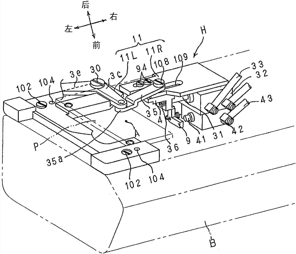
图4是表示上述防线迹开线装置的主要部分的结构的俯视图。 Fig. 4 is a plan view showing the structure of the main part of the above-mentioned stitch preventing device. the
图5是对上述防线迹开线装置的限位机构的结构及第一动作进行说明的主要部分的仰视图。 Fig. 5 is a bottom view of main parts for explaining the structure and first operation of the stopper mechanism of the above-mentioned stitch preventing device. the
图6是对上述限位机构的结构及第二动作进行说明的主要部分的仰视图。 Fig. 6 is a bottom view of main parts for explaining the structure and second operation of the stopper mechanism. the
图7是对上述限位机构的结构及第三动作进行说明的主要部分的仰视图。 Fig. 7 is a bottom view of main parts for explaining the structure and third operation of the stopper mechanism. the
图8是对上述限位机构的结构及第四动作进行说明的主要部分的仰视图。 Fig. 8 is a bottom view of main parts for explaining the structure and fourth operation of the stopper mechanism. the
图9是表示包括防线迹开线装置H在内的第一实施方式的横筒型双链环缝纫机的控制系统的结构的框图。 Fig. 9 is a block diagram showing a configuration of a control system of the horizontal cylinder type double chain link sewing machine including the stitch preventing device H according to the first embodiment. the
图10是按时间顺序表示上述用于防止开线的控制部8的动作内容的流程图。
FIG. 10 is a flow chart showing in chronological order the operation content of the above-mentioned
图11是上述防线迹开线装置进行的第一防开线动作的说明图。 Fig. 11 is an explanatory diagram of the first thread unraveling prevention operation performed by the above-mentioned stitch unraveling prevention device. the
图12是上述防线迹开线装置进行的第二防开线动作的说明图。 Fig. 12 is an explanatory diagram of the second thread unraveling prevention operation performed by the stitch unraveling prevention device. the
图13是上述防线迹开线装置进行的第三防开线动作的说明图。 Fig. 13 is an explanatory diagram of a third thread unraveling prevention operation performed by the stitch unraveling prevention device. the
图14是上述防线迹开线装置进行的第四防开线动作的说明图。 Fig. 14 is an explanatory diagram of the fourth thread unraveling prevention operation performed by the above-mentioned stitch unraveling prevention device. the
图15是上述防线迹开线装置进行的第五防开线动作的说明图。 Fig. 15 is an explanatory diagram of a fifth thread-unraveling prevention operation performed by the above-mentioned stitch-unraveling prevention device. the
图16是上述防线迹开线装置进行的第六防开线动作的说明图。 Fig. 16 is an explanatory diagram of the sixth thread unraveling prevention operation performed by the stitch unraveling prevention device. the
图17是上述防线迹开线装置进行的第七防开线动作的说明图。 Fig. 17 is an explanatory diagram of the seventh thread unraveling prevention operation performed by the above-mentioned stitch unraveling prevention device. the
图18是从缝制面料的背面观察第一实施方式的横筒型双链环缝纫机的双链环缝的线迹的结构的图。 Fig. 18 is a view showing the structure of the stitches of the double chain stitch of the horizontal cylinder type double chain sewing machine according to the first embodiment viewed from the back of the sewn material. the
图19是表示本发明第二实施方式的横筒型双链环缝纫机中的防线迹开线装置的主要部分的结构及第一防开线动作的说明图。 Fig. 19 is an explanatory view showing the configuration of main parts and the first thread unraveling prevention operation of the stitch unraveling prevention device in the horizontal cylinder type double chain link sewing machine according to the second embodiment of the present invention. the
图20是上述防线迹开线装置进行的第二防开线动作的说明图。 Fig. 20 is an explanatory diagram of the second thread unraveling prevention operation performed by the stitch unraveling prevention device. the
图21是上述防线迹开线装置进行的第三防开线动作的说明图。 Fig. 21 is an explanatory diagram of the third thread unraveling prevention operation performed by the stitch unraveling prevention device. the
图22是上述防线迹开线装置进行的第四防开线动作的说明图。 Fig. 22 is an explanatory diagram of the fourth thread unraveling prevention operation performed by the stitch unraveling prevention device. the
图23是上述防线迹开线装置进行的第五防开线动作的说明图。 Fig. 23 is an explanatory diagram of the fifth thread-unraveling prevention operation performed by the above-mentioned stitch-unraveling prevention device. the
图24是上述防线迹开线装置进行的第六防开线动作的说明图。 Fig. 24 is an explanatory diagram of the sixth thread unraveling prevention operation performed by the stitch unraveling prevention device. the
图25是上述防线迹开线装置进行的第七防开线动作的说明图。 Fig. 25 is an explanatory diagram of the seventh thread unraveling prevention operation performed by the stitch unraveling prevention device. the
图26是从缝制面料的背面观察通过与第一实施方式及第二实施方式不同的动作而获得的双链环缝的线迹的结构的图。 Fig. 26 is a view of the structure of the stitches of the double chain loop stitch obtained by operations different from those of the first embodiment and the second embodiment, viewed from the back of the sewn material. the
图27是大致示出一般双链环缝的缝制结束部分的线迹的结构的仰视图。 Fig. 27 is a bottom view schematically showing the structure of the stitches of the sewing end portion of a general double chain loop seam. the
图28是大致示出在现有技术中提出的缝制结束部分的线迹的结构的仰视图。 Fig. 28 is a bottom view roughly showing the structure of the stitches of the sewing end portion proposed in the prior art. the
图29是大致示出将现有技术应用在一根针中的情况下的缝制结束部分的线迹的结构的仰视图。 Fig. 29 is a bottom view schematically showing the structure of stitches at the end of sewing when the prior art is applied to one needle. the
(符号说明) (Symbol Description)
1 弯针 1 looper
2 针 2 pins
3 挂线钩 3 Hanging hooks
4 限位构件 4 limit member
6 弯针线保持体 6 Looper thread holder
8 控制部 8 Control Department
9 摆动杆 9 swing lever
10 弯针线 10 hook thread
20 缝线 20 stitches
20a、20b 缝线环 20a, 20b Suture loops
30 上下方向的支轴 30 Support shaft in the up and down direction
32 线操作汽缸(钩致动器) 32 Wire Operated Cylinders (Hook Actuators)
35 连接杆(连接构件) 35 connecting rod (connecting member)
42 限位汽缸(限位致动器) 42 limit cylinder (limit actuator)
91 弹簧 91 spring
A 落针位置 A Needle drop position
B 缝纫机底座部 B Sewing machine base part
P 针板 P needle plate
M 双链环缝的线迹 M The stitch of the double chain link seam
H 防线迹开线装置 H anti-stitch opening device
具体实施方式 Detailed ways
以下,基于附图对本发明的实施方式进行说明。 Embodiments of the present invention will be described below based on the drawings. the
图1是本发明第一实施方式的横筒型双链环缝纫机的整体外观立体图,图2及图3是表示第一实施方式的横筒型双链环缝纫机所安装的防线迹开线装置的主要部分的结构的立体图,图4是表示上述防线迹开线装置的主要部分的结构的俯视图。在以下说明中,使用图2~图4中箭头所示的“左、右”及“前、后”的表述来进行说明。在此,“前”是靠近缝制作业者一侧,“后”是远离缝制作业者一侧,“左、右”是从靠近缝制作业者的前侧观察时的“左、右”。 Fig. 1 is a perspective view of the overall appearance of a horizontal cylinder type double chain link sewing machine according to the first embodiment of the present invention, and Figs. As a perspective view of the structure of the main part, FIG. 4 is a plan view showing the structure of the main part of the above-mentioned stitch preventing device. In the following description, the expressions "left, right" and "front, rear" indicated by arrows in FIGS. 2 to 4 are used for description. Here, "front" is the side close to the sewing operator, "rear" is the side away from the sewing operator, and "left and right" are "left and right" when viewed from the front side close to the sewing operator . the
如图1所示,第一实施方式的横筒型双链环缝纫机的缝纫机机臂部C与缝纫机底座部B彼此大致平行地从缝纫机主体部D的上下位置朝向左侧延伸设置。如图4所示,上述横筒型双链环缝纫机包括:弯针1;一根针2(参照图11~图17);安装于缝纫机底座部B的上表面的针板台11;安装在该针板台11上的防线迹开线装置H;以及安装在上述针板台11上的针板P。
As shown in FIG. 1 , in the horizontal cylinder type double chain link sewing machine according to the first embodiment, the sewing machine arm part C and the sewing machine base part B extend from the upper and lower positions of the sewing machine main body D toward the left side substantially parallel to each other. As shown in Figure 4, the above-mentioned horizontal cylinder type double chain link sewing machine includes: a
针2以位于针杆12的中心的延长线上的方式通过针安装件13安装于针杆12的下端部,并进行上升及下降,该针杆12与缝纫机机臂部C内的缝纫机主轴(未图示)的旋转联动地上下运动。图2、图4中的A表示针2的落针位置(下降位置)。落针位置A被设定在针板P的大致中央部。
The
弯针1配置于缝纫机底座部B内,并通过未图示的弯针驱动机构的动作而在与针2的上下运动路径大致正交的方向上进行进退(左进及右退)动作。图4的实线表示弯针1朝左进位置动作的状态,图4的虚线表示弯针1朝右退位置动作的状态。如图4的实线所示,处于左进位置的弯针1的前端部越过落针位置A而朝左侧延伸出,如图4的虚线所示,处于右退位置的弯针1的前端部位于朝落针位置A右侧离开的位置上。
The
横筒型双链环缝纫机通过针2的上升及下降动作和弯针1的左进及右退动 作而对设置在针板P上的缝制面料(未图示)进行缝制。缝制面料被按压件(未图示)按压在针板P上,通过设于缝纫机底座部B内部的送料机构的动作而朝图4的箭头Y方向送料移动。送料机构包括送料牙,该送料牙反复进行在针板P上突出并朝后方移动及没入针板P下并朝前方返回移动的动作,通过上述送料牙将缝制面料间歇地朝箭头Y方向送料移动。
The horizontal cylinder type double chain link sewing machine sews the sewing material (not shown) set on the needle plate P through the rising and falling motion of the
上述针杆12、弯针驱动机构及送料机构是通过来自缝纫机主轴(未图示)的传动而彼此同步地动作的公知机构。针2分别对缝线20(参照图11~图17)进行保持,在缝制面料停止送料移动时,针2贯穿该缝制面料而到达针板P下方,然后针2上升后朝缝制面料的上方拔出。弯针1对弯针线10(参照图11~图17)进行保持,在针2开始上升的同时左进,以捉住形成在针板P下方的缝线20的线环20a。缝制面料在针2上升时被送料移动。针2贯穿送料移动后的缝制面料并下降,以捉住右退中的弯针1所保持的弯针线10。双链环缝纫机反复进行以上动作而在缝制面料上形成双链环缝的线迹。
The
上述这种横筒型双链环缝纫机所包括的防线迹开线装置H包括:缝线保持机构;限位机构;连接杆35,该连接杆35作为使上述缝线保持机构的挂线钩3(在下文中叙述)与上述限位机构的限位构件4(在下文中叙述)联动地连接的连接构件;以及控制部8(在下文中叙述)。
The anti-stitch thread opening device H included in the above-mentioned horizontal cylinder type double-link sewing machine includes: a suture holding mechanism; a limit mechanism; a connecting
上述缝线保持机构具有挂线钩3和往复运动式的线操作汽缸32,该往复运动式的线操作汽缸32作为驱动上述挂线钩3使其在远离上述弯针1的待机位置与靠近上述弯针1的挂线位置之间以上下方向的支轴30为中心摆动的钩致动器。作为挂线钩3的摆动中心的支轴30配置在针板P的右后侧角部的附近,并被支承在上述针板台11上。
The suture holding mechanism has a
挂线钩3具有圆弧状的弯曲形状,其在从支轴30朝左侧延伸的支承臂3e的前端部以朝向前方折返的方式连续设置。挂线钩3的前端部在针板P的下侧从左侧后方弯向落针位置A,在该前端部形成有朝外侧突出的钩部3b。支承臂3e具有从支轴30朝向前方延伸的延设部3c,在该延设部3c的前端部连接有连接杆35的一端部。
The
如图5~图8所示,上述限位机构由限位构件4、摆动杆9、弹簧91和单 动式(朝向左方的压出驱动式)限位汽缸42构成,其中,上述限位构件4通过止动螺钉36而被固定在上述线操作汽缸32的输出杆31的前端部(左端部),利用经由送气管33供给来的工作气体使线操作汽缸32伸缩动作,从而驱动该限位构件4在左右方向上直线地往复移动,上述摆动杆9能与该限位构件4的一部分卡合及解除卡合,上述弹簧91对该摆动杆9施力使其与上述限位构件4的一部分卡合,并朝使上述挂线钩3位于待机位置的方向摆动,上述单动式限位汽缸42作为克服该弹簧91的摆动作用力而强制使上述摆动杆9与上述限位构件4的一部分解除卡合的限位致动器。
As shown in Figures 5 to 8, the above-mentioned limiting mechanism is composed of a limiting
上述限位汽缸42的输出杆41构成为,随着利用经由送气管43供给来的工作气体而驱动限位汽缸42朝左侧按压,使上述摆动杆9克服上述弹簧91的摆动作用力而朝逆时针方向摆动。
The
摆动杆9能绕上下方向的支轴90为中心摆动地支承在摆动杆安装台92的上表面。摆动杆9在前端部具有能与上述限位构件4的一部分卡合的卡合爪9a,如图5所示,在通过线操作汽缸32的伸长动作来驱动上述限位构件4朝左侧移动时,即在挂线钩3移动至待机位置时,摆动杆9在弹簧91的作用力的作用下与限位构件4的侧部接触,在通过线操作汽缸32的收缩动作来驱动上述限位构件4朝右侧移动时,如图6所示,摆动杆9在弹簧91的作用力的作用下以支轴90为中心顺时针摆动而使其前端的卡合爪9a处于能与限位构件4的一部分卡合的状态。
The
此外,如图7所示,通过使收缩的线操作汽缸32再次伸长少许,摆动杆9前端的卡合爪9a就会与限位构件4的一部分卡合,而使限位构件4朝左侧的驱动移动暂时停止。在如上所述限位构件4暂时停止的状态下,上述挂线钩3经由连接杆35移动并停止在上述待机位置与挂线位置之间的保持位置处。此时,挂线钩3前端的钩部3b从图4所示的挂线位置(落针位置A)朝左后方移动,钩住缝线20后保持在上述保持位置上。
In addition, as shown in FIG. 7 , by extending the contracted wire-operated cylinder 32 a little again, the engaging
此外,如图8所示,随着限位汽缸42伸长而驱动输出杆41朝左侧按压,使上述摆动杆9克服上述弹簧91的摆动作用力而朝逆时针方向摆动,以使该摆动杆9前端的卡合爪9a解除与限位构件4的一部分卡合,并解除限位构件4 的暂时停止。藉此,线操作汽缸32最大限度地进行伸长动作而使挂线钩3经由连接杆35摆动返回至待机位置。
In addition, as shown in FIG. 8 , as the
如上所述,在第一实施方式中,通过线操作汽缸32及限位汽缸42的伸缩动作,使缝线保持机构的挂线钩3在上述待机位置、挂线位置及保持位置之间摆动。
As described above, in the first embodiment, the thread-hanging
第一实施方式的横筒型双链环缝纫机包括在缝制结束后将缝线20及弯针线10切断的切线机构5。如图16及图17所示,上述切线机构5具有切线钩50、切线刀51、将切线钩50按压至与切线刀51接触的滑动接触部的板簧59以及切线致动器58(参照图9)。切线钩50在其前端部包括朝向后方突出设置的第一钩部52和第二钩部53。由于切线机构5是公知的,因此,省略其它详细结构的说明及图示。
The horizontal cylinder type double chain link sewing machine of the first embodiment includes a thread cutting mechanism 5 that cuts the
另外,在第一实施方式的横筒型双链环缝纫机中,采用以下结构:如图2~图4所示,安装于缝纫机底座部B上表面的针板台11被分为左侧针板台部11L和右侧针板台部11R这两个部分。上述针板P通过止动螺钉100能拆卸地安装在左侧针板台部11L的上表面,并且,左侧针板台部11L对作为上述缝线保持机构的挂线钩3的摆动中心的支轴30进行支承。
In addition, in the horizontal cylinder type double chain link sewing machine according to the first embodiment, the following structure is adopted: as shown in FIGS. There are two parts, the
在被一分为二而成的左侧针板台部11L的、靠近左端部的前后多处部位(两个部位)上,具体来说,在图4中虚线所示的缝纫机机臂部C的前端(左端)附近、远离上述针板P的安装部位的部位上,形成有螺钉孔101,通过与上述螺钉孔101螺合的止动螺钉构件102,左侧针板台部11L能旋紧固定及解除固定(可装拆)地安装在缝纫机底座部B的上表面上。
On the left needle
另外,如图3所示,在缝纫机底座部B的上表面及上述左侧针板台部11L上、远离由上述止动螺钉构件102在两处进行旋紧固定的旋紧固定部位的部位上,形成有止动销103及与该止动销103嵌合的销孔104,通过将销孔104从上方套在止动销103上并与之嵌合,就可将左侧针板台部11L相对于缝纫机底座部B定位为规定位置及姿势,在此状态下,通过将上述止动螺钉构件102拧入螺钉孔101,就可将左侧针板台部11L旋紧固定在缝纫机底座部B的上表面上。
In addition, as shown in FIG. 3 , on the upper surface of the sewing machine base part B and the above-mentioned left needle
另外,在本第一实施方式中,对止动销103从缝纫机底座部B的上表面朝向上方突出,销孔104形成于左侧针板台部11L的情况进行了说明及图示,但也可以是止动销103从左侧针板台部11L的下表面朝向下方突出,销孔104形成在缝纫机底座部B的上表面上的方式。
In addition, in the first embodiment, the case where the stopper pin 103 protrudes upward from the upper surface of the sewing machine base portion B and the
另一方面,被一分为二而成的右侧针板台部11R构成对上述线操作汽缸32及限位汽缸42进行支承的汽缸安装台部(以下,将该右侧针板台部11R称为汽缸安装台部),在该汽缸安装台部11R的下部配置有上述限位机构。详细来说,如图5~图8所示,在汽缸安装台部11R的下表面上通过安装螺钉105固定支承有线操作汽缸32,并且在该线操作汽缸32的下部以两级重叠的状态配置有限位汽缸42,该限位汽缸42通过安装螺钉106被固定支承在汽缸安装台部11R上。
On the other hand, the needle
上述汽缸安装台部11R通过止动螺钉构件70以固定状态组装在缝纫机底座部B的侧面上。在此,固定状态是指在将防线迹开线装置H组装在缝纫机底座部B上时通过对上述止动螺钉构件107进行旋紧而被固定在规定的位置上,在组装之后,不进行位置调节等就被固定在规定的组装位置上的状态。
The above-mentioned
上述连接杆35的一端(右端)部通过销螺钉108能转动地连接至限位机构的限位构件4上。在与利用销螺钉108将上述连接杆35的一端和限位构件4连接的连接部相对应的部位的汽缸安装台部11R上,形成有沿左右方向较长的长槽109,以允许随着线操作汽缸32的伸缩而可在左右方向上直线往复运动的限位构件4的直线往复运动。
One end (right end) of the connecting
此外,在上述连接杆35的另一端与和上述挂线钩3相连的延设部3c连接的连接端部分35a朝下方弯曲相当于上述延设部3c的大致厚度量的距离。在朝下方弯曲的连接杆35的连接端部分35a上,朝向上方突出有销钉110,另一方面,在上述延设部3c上,形成有能从上述销钉110的上方套在该销钉110上及能朝上方拔出的连接孔111。
Furthermore, a
藉此,在解除左侧针板台部11L与缝纫机底座部B的固定来将其从缝纫机底座部B取下时,不需要进行对将连接杆35与延设部3c固定连接的、例如止动螺钉等进行拧松操作来解除两者的联动状态这样的作业,仅仅通过朝上方提 起左侧针板台部11L,就可将延设部3c的连接孔111从销钉110朝上方拔出来解除连接杆35与延设部3c(挂线钩3)的联动状态。此外,在将左侧针板台部11L安装于缝纫机底座部B时,也仅仅通过使左侧针板台部11L从上方朝向缝纫机底座部B移动,就可将连接孔111从上方套在销钉110上而使连接杆35与延设部3c(挂线钩3)返回联动状态。另外,连接杆35的连接端部分35a未必需要朝下方弯曲。也就是说,连接杆35在其全长上也可以呈扁平的板状。
Thereby, when releasing the fixation of the left needle
而且,将上述限位机构的摆动杆9支承成能绕上下方向的支轴90为中心摆动的摆动杆安装台92以通过左右方向较长的长孔93和止动螺钉94而能左右调节位置的方式安装在汽缸安装台部11R上。即便在将汽缸安装台部11R通过止动螺钉构件107以固定状态组装于缝纫机底座B之后,也可通过调节摆动杆安装台92相对于汽缸安装台部11R的左右位置,来任意地调节弯针1从保持于挂线钩3的缝线环20a拔出的时机,藉此,能可靠地进行用于防线迹开线的自绕线。
Moreover, the
在包括采用以上所说明的将针板台11一分为二成左侧针板台部11L和右侧针板台部11R的结构的防线迹开线装置H的第一实施方式的横筒型双链环缝纫机中,在将防线迹开线装置H组装到缝纫机底座部B时,能将左右一分为二的针板台11的左侧针板台部11L及右侧的汽缸安装台部11R分别安装于缝纫机底座部B。因此,与处理左右两侧针板台部11L、11R一体化而在左右方向上又长又大的针板台的情况相比,能用较少的力气轻松地进行将防线迹开线装置H整体安装(组装)于缝纫机底座部B的作业。
In the horizontal cylinder type of the first embodiment including the stitch prevention thread opening device H adopting the above-described structure in which the
另外,暂时将针板台11(左侧针板台部11L及右侧的汽缸安装台部11R)组装于缝纫机底座部B之后,在需要通过对例如弯针1及其驱动用构件等、位于针板台11下部且收容在缝纫机底座部B内部的构成缝制的构件的位置及运动轨迹进行修正来调节缝制性能的情况下,或是在需要对位于针板台11下部且收容在缝纫机底座部B内部的各种部件进行维修、更换等维护的情况下,在对与送气管33、43连接的线操作汽缸32及限位汽缸42进行组装时牢固地固定支承在规定位置上的汽缸安装台部11R不需要从缝纫机底座部B取下,只要解除左侧针板台部11L与缝纫机底座部B的固定后将其取下,就能确保足够大 的作业空间以容易进行缝制性能的调节及维护。
In addition, after temporarily assembling the needle plate base 11 (the left needle
图9是表示上述包括防线迹开线装置H在内的第一实施方式的横筒型双链环缝纫机的控制系统的结构的框图。 FIG. 9 is a block diagram showing a configuration of a control system of the horizontal cylinder type double chain link sewing machine including the stitch preventing device H according to the first embodiment. the
对双链环缝纫机的控制部8分别输入来自踏板开关21的踩下信号21a及踩回信号21b、针2处于上死点附近时发出的针位置信号22、切线信号23及拨线信号24。
The
另一方面,从控制部8分别朝线操作汽缸32、限位汽缸42及切线致动器58输出动作控制信号。挂线钩3及弯针线保持体6按照从控制部8输出至线操作汽缸32及限位汽缸42的动作控制信号而如上所述地动作,切线机构5的切线致动器58按照从控制部8输出的切线信号23而分别进行伸缩动作。
On the other hand, operation control signals are output from the
此外,从控制部8还分别对作为缝纫机主轴的驱动源的缝纫机马达80、使压脚用按压件升降的压脚汽缸81、如后所述将被切断的缝线20扫起的空气扫线器82、对缝制面料的送料量进行调节的减少送料机构83以及对弯针线10朝弯针1的送出进行抑制的弯针线抑制机构84输出动作控制信号。
In addition, from the
减少送料机构83通过改变送料机构中的送料牙的动作形态、例如使送料牙的动作路径相对于针板P倾斜来缩短在针板P上突出的突出时间,来缩短送料牙作用在针板P上的缝制面料上的时间,或是通过改变使送料牙循环动作的杆的长度,来减小送料牙的单位送料间距等,以减少缝制面料的送料量,由于上述减少送料机构83是公知的,因此,省略详细的图示及说明。
The
弯针线抑制机构84包括:夹线盘,该夹线盘对送入弯针1的弯针线10的中途部分进行夹持;以及致动器,该致动器进行动作,以使上述夹线盘对弯针线夹持的强度增减,上述弯针线抑制机构84通过提高夹线盘对弯针线夹持的强度就可增加对弯针线10施加的阻力,从而可抑制弯针线10的送出,由于该弯针线抑制机构84是公知的,因此,省略其详细的图示及说明。
The looper
在完成形成双链环缝的线迹的缝制之后,控制部8使挂线钩3与缝纫机马达80、压脚汽缸81、空气扫线器82、减少送料机构83及弯针线抑制机构84关联地动作,就可执行防止双链环缝的线迹开线的动作。
After finishing the sewing of the stitches forming the double chain loop seam, the
图10是按时间顺序表示用于防止开线的控制部8的动作内容的时序图。 控制部8是包括CPU、ROM及RAM的计算机,按照图10的时序图的防止开线的动作是通过按照存储在ROM中的控制程序进行的CPU的一系列动作来执行的。
FIG. 10 is a timing chart showing in chronological order the operation content of the
图11~图17是由第一实施方式的横筒型双链环缝纫机的防线迹开线装置H进行的防开线动作的说明图,其表示通过按照图10的时序图进行的控制部8的动作而产生的挂线钩3及切线钩50的动作状态。
11 to 17 are explanatory views of the thread unraveling prevention operation performed by the stitch unraveling prevention device H of the horizontal cylinder type double chain link sewing machine according to the first embodiment, and show the
使用缝纫机的缝制作业者在结束通常的缝制时会停止踩下用于驱动缝纫机的踏板的操作,然后执行防开线动作,但此时,对上述踏板进行踩回操作。踏板开关21设置在踏板上,在踩下操作时输出踩下信号21a,在踩回操作时输出踩回信号21b。
The sewing worker who uses the sewing machine stops stepping on the pedal for driving the sewing machine when finishing normal sewing, and then performs the thread unraveling prevention action, but at this time, the above-mentioned pedal is stepped on. The
当结束通常的缝制,在图10的S1时刻下,用于驱动缝纫机的踏板从踩下状态返回至中立状态时,即在踏板开关21没有输出踩下信号21a及踩回信号21中的任意一个的状态时,控制部8参照从输入侧输入的针位置信号22而对缝纫机马达80输出停止指令。藉此,缝纫机在针2位于上死点附近、弯针1左进的状态下暂时停止。
When the normal sewing is finished, at the moment S1 in FIG. In one state, the
然后,控制部8待机直至对上述踏板进行了踩回操作。在图10的S2时刻下进行踩回操作,从而在输入侧输入踩回信号21b的情况下,控制部8首先在S3时刻,对减少送料机构83发出动作开始指令,以使减小送料牙的单位送料间距等缝制面料的送料量比通常缝制时的送料量小(少),然后,开始以下所述的防开线动作。另外,上述减少送料机构83使送料牙以较小的送料量对缝制面料进行送料的开始时期(S3)被设定为利用挂线钩3使缝线环20a位于比针2的下降位置更靠弯针1的前进端侧的位置之前的一针半以上之前的时刻。
Then, the
另外,控制部8在从踏板开关21再次输入踩下信号21a时,返回通常的缝制动作,因此,缝制作业者通过再次对踏板进行踩下操作,就能继续通常的缝制。另外,在图10中,在S1时刻与S2时刻之间维持中立状态,但并非必须要维持上述中立状态,结束通常的缝制时的踏板操作也可以连续地从踩下状态移动至踩回状态。在该情况下,在移动过程中经过中立位置时,处于踩下信号21a和踩回信号21b都没有被输出的无信号状态,控制部8以上述无信号状态作为触发信号,从而如上所述在实现使针2上升至上死点附近、弯针1左进 的状态后,开始防开线动作。
In addition, since the
此外,在图10的时序图中,S2时刻下的踏板的踩回操作在执行以下说明的防开线动作中继续,但在防开线动作结束之前不需要继续进行这种踩回操作,在停止输入踩回信号21b之后,防开线动作也可在控制部8的控制下继续执行。
In addition, in the timing diagram of Fig. 10, the stepping back operation of the pedal at the time of S2 continues during the thread opening prevention action described below, but it is not necessary to continue this stepping back operation before the thread opening prevention action ends. After the stepping back
图11表示防开线动作开始时的针2、弯针1及挂线钩3的状态。针2处于朝由一根缝线20和一根弯针线10形成双链环缝的线迹M后的缝制面料上方拔出的状态。弯针1在缝制面料的下侧左进,而处于捉住针2形成的缝线环20a的状态。若在此状态下切断缝线20及弯针线10,则可形成图27所示的缝制结束部。
Fig. 11 shows the states of the
在开始防开线动作之后,控制部8首先在图10的S4时刻对输出侧的线操作汽缸32发出动作指令。藉此,线操作汽缸32从图5所示的伸长状态朝图6所示的收缩状态动作,以驱动限位构件4朝右侧移动,随之,挂线钩3经由限位构件4及连接杆35而以支轴30为中心摆动,以从待机位置移动至挂线位置,此时,挂线钩3前端的钩部3b钩住的缝线环20a,并且限位机构中的摆动杆9在弹簧91的作用力的作用下以支轴90为中心朝顺时针方向摆动,其前端的卡合爪9a处于能与限位构件4的一部分卡合的状态。
After starting the anti-thread opening action, the
随后,控制部8对线操作汽缸32发出动作指令,该线操作汽缸32从图6所示的状态稍稍伸长至图7所示的状态,从而驱动限位构件4朝左侧直线移动。在上述线操作汽缸32少许伸长时,摆动杆9前端的卡合爪9a与限位构件4的一部分卡合。藉此,限位构件4朝左侧的驱动移动被暂时停止。这样,在限位构件4朝左侧的驱动移动被暂时停止的状态下,如图12所示,上述挂线钩3经由连接杆35而移动并停止在上述待机位置与挂线位置之间的保持位置上,将缝线环20a保持在上述保持位置。
Subsequently, the
如上所述,在使挂线钩3移动并停止在上述保持位置上之后,在图10的S5时刻下,控制部8对缝纫机马达80和弯针线抑制机构84发出动作指令。上述动作指令是参照针位置信号22,在针2下降之后再次上升到上死点附近位置之前发出的。藉此,对缝制面料进行一针的缝制动作。上述一针的缝制是在通 过减少送料机构83的动作而以比通常的缝制时更小的送料量的情况下执行的。此外,上述一针的缝制是在通过弯针线抑制机构84的动作而使弯针线10向弯针1的送出受到抑制的状态下执行的。藉此,由于能使缝制结束的弯针线10的系紧更好,因此,能提高后述的防开线效果。
As described above, after the
如图12所示,挂线钩3继续对缝线20进行保持,直至完成缝制面料的送料移动,针2穿过挂线钩3所保持的缝线环20a,并捉住该缝线环20a为止。此时,如图12所示,弯针线10位于横穿针2的后侧的位置。
As shown in Figure 12, the
控制部8在针2捉住缝线环20a的时刻,即在刚过图10的S6之后的时刻下,对限位机构的限位汽缸42发出动作指令,使该限位汽缸42伸长,随之驱动输出杆41朝左侧压出。藉此,如图8所示,上述摆动杆9克服上述弹簧91的摆动作用力而朝逆时针方向摆动,以使该摆动杆9前端的卡合爪9a解除与限位构件4的一部分卡合,并解除限位构件4的暂时停止。通过上述对限位构件4的停止解除操作,线操作汽缸32在S6时刻下伸长到最大限度。藉此,如图13所示,挂线钩3经由限位构件4及连接杆35而以支轴30为中心摆动,从上述保持位置返回移动至待机位置,解除对缝线环20a的保持。
When the
接着,弯针1在针2下降的同时进行右退动作,从捕捉到的缝线环20a中拔出。如图14所示,通过拔出上述弯针1,针2与通常的缝制时一样处于捕捉到弯针线10的状态。
Next, the
在上述状态下,弯针1转换为左进,针2转换为上升。如图15所示,左进的弯针1捉住缝线环20a1,上升的针2朝缝制面料的上方拔出。藉此,弯针1所捉住的缝线20处于用缝线20对先前形成的缝线环20a进行绕线的所谓自绕线(日文:自糸ル一ピング)的状态。
In the above state,
在一针的缝制动作之后,在针2上升到上死点附近,弯针1到达左进端附近的状态下结束。然后,控制部8在图10的S7时刻,停止减少送料机构83的动作,并在该状态下待机直至输入了切线信号23为止。随后,若在图10的S8时刻下接收到切线信号23,则对切线机构5的切线致动器58发出动作指令,使该切线致动器58进行规定的动作,藉此,如图16所示,切线钩50沿着弯针1的上部到达前进端。此时,切线钩50前端部的第一钩部52穿过弯针1所 保持的缝线环20a内而到达从弯针1的前端延伸至缝制面料的弯针线10的左侧,第二钩部53从左侧与缝线20相对。
After the sewing operation of one stitch, the
接着,到达前进端的切线钩50进行右退动作。此时,第一钩部52捕捉弯针线10,第二钩部53捕捉缝线20。被如上所述捕捉的弯针线10及缝线20被拉至切线钩50的退入端,并如图17所示,通过与切线刀51的前端刃部滑动接触而被切断。接着,被切断的弯针线10的端部在比切断位置更靠弯针1一侧被保持成夹在切线钩50与板簧59之间的状态。
Next, the
弯针线抑制机构84继续动作直至结束上述切线动作,从而对从弯针1前端延伸至缝制面料的弯针线10施加规定的张力。藉此,切线钩50前端的第一钩部52能可靠地捕捉没有松弛的弯针线10,并将其切断。
The looper
在结束上述切断动作之后,控制部8待机,直至输入有拨线信号24,若在图10的S9时刻输入有拨线信号24,则控制部8将动作指令输出至空气扫线器82来使该空气扫线器82动作。上述空气扫线器82吹出空气,以将与针2连续的缝线20的切断端部吹起。然后,控制部8在图10的S10时刻将动作指令输出至压脚汽缸81以使该压脚汽缸81动作,从而使压脚用的按压件上升来结束一系列的防开线动作。
After the above-mentioned cutting operation is finished, the
在用于防止上述开线的一针的缝制动作时,从缝制面料的背面拔出的缝线20穿过在通常的缝制时最后形成于缝制面料背面的最终缝线环20a内,并对该最终缝线环20a进行自绕线,以形成单环缝的线迹M。因此,如图18所示,弯针线10处于被按压在缝线20与最终缝线环20a之间的状态。
During the sewing action of one stitch for preventing the above-mentioned splitting, the
另外,因上述减少送料机构83而使送料牙以较小的送料量进行缝制面料的送料是从用于防止开线的一针的缝制动作之前的阶段、具体而言是从利用挂线钩3使缝线环20a位于比针2的下降位置更靠弯针1的前进端侧的位置之前的一针半以上之前的时刻(图10的S3时刻)开始的,因此,如图18所示,由自绕线之前的互绕线产生的线迹的间距P比由这之前的互绕线产生的线迹的间距P0小,从而使弯针线10的切断端部被朝图18的箭头方向拉伸的情况下的防脱落阻力变大。因此,在处于图18所示的状态的情况下,能利用自绕线部与伴随着由自绕线之前的互绕线产生的线迹的间距P变小而使弯针线10的 防脱落阻力增大的相互作用来可靠地防止双链环缝的线迹M的开线。
In addition, due to the above-mentioned reduction of the
另外,在第一实施方式的情况下,采用以下结构:使用弹簧91对限位机构中的摆动杆9施力以使其朝缝线保持机构中的挂线钩3位于上述待机位置的方向摆动。藉此,由于利用弹簧9的作用力就可进行限位构件4朝返回方向的动作(挂线钩位于待机位置的方向的动作),因此,能使用单动式气缸作为使与限位构件4的一部分卡合及解除卡合的摆动杆9动作的限位汽缸42,因而,可实现限位汽缸42的小型化、低成本化。
In addition, in the case of the first embodiment, a structure is adopted in which the
接着,对本发明第二实施方式的横筒型双链环缝纫机进行说明。 Next, a horizontal cylinder type double chain link sewing machine according to a second embodiment of the present invention will be described. the
如图19所示,第二实施方式的横筒型双链环缝纫机除了下述两个结构与上述第一实施方式不同之外,其它结构与第一实施方式中说明的结构全都相同:一根针2以位于相对于针杆12的中心CL的延长线朝弯针1的前进侧变位的位置的方式通过针安装件13安装于针杆12的下端部,该针杆12与缝纫机机臂部C内的缝纫机主轴(未图示)的旋转联动地上下运动;以及包括弯针线保持体6,该弯针线保持体6能接近及远离弯针1,并在接近动作时,将从弯针1延伸出的弯针线10保持在比上述针2的下降位置更靠前侧的位置。因此,对于与第一实施方式不同的上述两个结构以外的结构,省略说明及具体的图示。
As shown in FIG. 19 , the horizontal cylinder type double chain link sewing machine of the second embodiment is the same as the structure described in the first embodiment except for the following two structures that are different from the above-mentioned first embodiment: The
对于第二实施方式的一根针2,通常,将使用左右两根针的横筒型双链环缝纫机的两根针中右侧的针从针安装件13上拆下而仅安装左侧的针来使用,因此,该左侧的一根针2相对于针杆12的中心CL的延长线朝弯针1的前进侧偏置。除了仅将左右两根针中的左侧的针用作偏置的一根针2之外,也可使用专用的偏置的一根针。
With regard to one
在通常的双链环缝纫机中,存在沿弯针1的进退动作方向排列设置三根或四根针来使用的例子。在三根针的情况下,既可以拆下位于针杆12的中心CL的针和右侧的针而将左侧的针用作偏置的一根针,也可以拆下左右两侧的针而仅使用位于针杆12的中心CL的延长线上的一根针。另外,在四根针的情况下,可考虑拆下右侧的三根针而将左侧的针用作偏置的一根针。
In an ordinary double chain sewing machine, there are examples in which three or four needles are arranged and used along the forward and backward motion direction of the
另外,如图4中假想线所示,上述弯针线保持体6具有圆弧状的弯曲形状, 并通过固定螺钉60以一起旋紧的状态固定于上述挂线钩3的基部。该弯针线保持体6的前端部大致沿着挂线钩3的左侧朝前方延伸,并在挂线钩3前端部的前侧弯向落针位置A,在该前端部形成有分支成双叉状的弯针线收纳部6a。
In addition, as shown by the phantom line in Figure 4, the above-mentioned
弯针线保持体6被往复运动式线操作汽缸32驱动而以支轴30为中心与缝线保持机构的挂线钩3一体地摆动。
The looper
图19~图25是由第二实施方式的横筒型双链环缝纫机的防线迹开线装置H进行的防开线动作的说明图,其表示通过按照图10的时序图进行的控制部8的动作而产生的挂线钩3、弯针线保持体6及切线钩50各自的动作状态。
19 to 25 are explanatory diagrams of the thread unraveling prevention operation performed by the stitch unraveling prevention device H of the horizontal cylinder type double chain link sewing machine according to the second embodiment, and show the
由于图10的从S1时刻起到S3时刻为止由缝制作业者进行的踏板操作以及伴随着该踏板操作而产生的由控制部8发出的对于减少送料机构83的动作开始指令等动作如第一实施方式中说明的那样,因此,省略它们详细的说明,对其以后的防开线动作开始后的动作进行说明。
Due to the pedal operation performed by the sewing operator from the time of S1 to the time of S3 in Fig. 10 and the actions such as the instruction to start the operation of the reducing
图19表示防开线动作开始时的针2、弯针1、挂线钩3及弯针线保持体6的状态。针2处于朝由一根缝线20和一根弯针线10形成双链环缝的线迹M后的缝制面料上方拔出的状态。
Fig. 19 shows the states of the
在开始防开线动作之后,控制部8首先在图10的S4时刻对输出侧的线操作汽缸32发出动作指令。藉此,线操作汽缸32从图5所示的伸长状态朝图6所示的收缩状态动作,以驱动限位构件4朝右侧移动,随之,挂线钩3及弯针线保持体6经由限位构件4及连接杆35而以支轴30为中心摆动,以从待机位置移动至挂线位置,此时,挂线钩3前端的钩部3b钩住缝线环20a,并且限位机构中的摆动杆9在弹簧91的作用力的作用下以支轴90为中心朝顺时针方向摆动,其前端的卡合爪9a处于能与限位构件4的一部分卡合的状态。
After starting the anti-thread opening action, the
随后,控制部8对线操作汽缸32发出下一个动作指令,该线操作汽缸32从图6所示的状态稍稍伸长至图7所示的状态,从而驱动限位构件4朝左侧直线移动。在上述线操作汽缸32少许伸长时,摆动杆9前端的卡合爪9a与限位构件4的一部分卡合。藉此,限位构件4朝左侧的驱动移动被暂时停止。这样,在限位构件4朝左侧的驱动移动被暂时停止的状态下,如图20所示,上述挂线钩3经由连接杆35而移动并停止在上述待机位置与挂线位置之间的保持位 置上,将缝线环20a保持在上述保持位置处,同时弯针线保持体6前进到弯针1的前侧而使前端的弯针线收纳部6a在落针位置A的前方对弯针线10进行保持。
Subsequently, the
如上所述,在使挂线钩3及弯针线保持体6移动并停止在上述保持位置上之后,在图10的S5时刻下,控制部8对缝纫机马达80和弯针线抑制机构84发出动作指令。上述动作指令是参照针位置信号22,在针2下降之后再次上升到上死点附近位置之前发出的。藉此,对缝制面料进行一针的缝制动作。上述一针的缝制是在通过减少送料机构83的动作而以比通常的缝制时更小的送料量的情况下执行的。此外,上述一针的缝制是在通过弯针线抑制机构84的动作而使弯针线10向弯针1的送出受到抑制的状态下执行的。藉此,由于能使缝制结束的弯针线10的系紧更好,因此,能提高后述的防开线效果。
As described above, after the
如图20所示,挂线钩3及弯针线保持体6继续对缝线20及弯针线10进行保持,直至完成缝制面料的送料移动,针2穿过挂线钩3所保持的缝线环20a,并捉住该缝线环20a为止。此时,如图20所示,弯针线10位于横穿针2的前侧的位置。
As shown in Figure 20, the
控制部8在针2捉住缝线环20a的时刻,即在刚过图10的S6之后的时刻,对限位机构的限位汽缸42发出动作指令,使该限位汽缸42伸长,随之驱动输出杆41朝左侧压出。藉此,如图8所示,上述摆动杆9克服上述弹簧91的摆动作用力而朝逆时针方向摆动,以使该摆动杆9前端的卡合爪9a解除与限位构件4的一部分卡合,并解除限位构件4的暂时停止。通过上述对限位构件4的停止解除操作,线操作汽缸32在S6时刻下伸长到最大限度。藉此,如图21所示,挂线钩3及弯针线保持体经由限位构件4及连接杆35而以支轴30为中心摆动,从上述保持位置返回移动至待机位置,以解除对缝线环20a及弯针线10的保持。
When the
接着,弯针1在针2下降的同时进行右退动作,从捕捉到的缝线环20a中拔出。如图22所示,通过拔出上述弯针1,针2与通常的缝制时一样处于捕捉到弯针线10的状态。
Next, the
在上述状态下,弯针1转换为左进,针2转换为上升。如图23所示,左 进的弯针1捉住缝线环20a1,上升的针2朝缝制面料的上方拔出。藉此,弯针1所捉住的缝线20处于用缝线20对先前形成的缝线环20a进行绕线即所谓自绕线的状态。
In the above state,
一针的缝制动作在针2上升到上死点附近且弯针1到达左前进端附近的状态下结束。然后,控制部8在图10的S7时刻,停止减少送料机构83的动作,并在该状态下待机直至输入了切线信号23为止。随后,若在图10的S8时刻下接收到切线信号23,则对切线机构5的切线致动器58发出动作指令,使该切线致动器58进行规定的动作,藉此,如图24所示,切线钩50沿着弯针1的上部到达前进端。此时,切线钩50前端部的第一钩部52穿过弯针1所保持的缝线环20a内而到达从弯针1的前端延伸至缝制面料的弯针线10的左侧,第二钩部53从左侧与缝线20相对。
The sewing operation of one stitch ends in a state where the
接着,到达前进端的切线钩50进行右退动作。此时,第一钩部52捕捉弯针线10,第二钩部53捕捉缝线20。被如上所述捕捉的弯针线10及缝线20被拉至切线钩50的退入端,并如图25所示,通过与切线刀51的前端刃部滑动接触而被切断。接着,被切断的弯针线10的端部在比切断位置更靠弯针1一侧被保持成夹在切线钩50与板簧59之间的状态。
Next, the
弯针线抑制机构84继续动作直至结束上述切线动作,从而对从弯针1前端延伸至缝制面料的弯针线10施加规定的张力。藉此,切线钩50前端的第一钩部52能可靠地捕捉没有松弛的弯针线10,并将其切断。
The looper
在结束上述切断动作之后,控制部8待机,直至输入有拨线信号24,若在图10的S9时刻输入有拨线信号24,则控制部8将动作指令输出至空气扫线器82来使该空气扫线器82动作。上述空气扫线器82吹出空气,以将与针2连续的缝线20的切断端部吹起。然后,控制部8在图10的S10时刻将动作指令输出至压脚汽缸81以使该压脚汽缸81动作,从而使压脚用的按压件上升来结束一系列的防开线动作。
After the above-mentioned cutting operation is finished, the
通过根据上述一系列的防开线动作,在第二实施方式的横筒型双链环缝纫机中,与第一实施方式的情况相同,也能得到图18所示的双链环缝的线迹M的结构。根据该双链环缝的线迹M,与第一实施方式的情况相同,能利用自绕 线部与伴随着由自绕线之前的互绕线产生的线迹的间距P变小而使弯针线10的防脱落阻力增大的相互作用来可靠地防止开线。
Through the above-mentioned series of thread unraveling prevention operations, in the horizontal cylinder type double chain link sewing machine of the second embodiment, as in the case of the first embodiment, the stitches of the double chain link stitch shown in FIG. 18 can also be obtained. The structure of M. According to the stitches M of this double chain loop stitch, as in the case of the first embodiment, the pitch P between the self-winding part and the stitches produced by the inter-winding before the self-winding can be reduced to make the bend The increased interaction of the anti-dropping resistance of the
除此之外,在第二实施方式的横筒型双链环缝纫机的情况下,在使弯针1处于前进状态下结束通常缝制之后,利用接近弯针1的弯针线保持体6,将从弯针1延伸至缝制面料的弯针线10保持在比针2的下降位置更靠前侧的位置,不仅对缝线20,也能对弯针线10可靠地进行定位。因此,能更可靠地进行自绕线,并能更可靠地实现防线迹开线效果。
In addition, in the case of the horizontal cylinder type double chain link sewing machine of the second embodiment, after normal sewing is completed with the
另外,在第二实施方式的横筒型双链环缝纫机的情况下,弯针线保持体6以一起旋紧的状态固定于缝线保持机构中的挂线钩3,并能与挂线钩3一体地接近及远离弯针1,因此,能使缝线保持机构的驱动机构兼用作弯针线保持体6的驱动机构,从而能尽量使防线迹开线装置H整体的结构小型简化且低成本化。
In addition, in the case of the horizontal cylinder type double-chain ring sewing machine of the second embodiment, the looper
另外,在上述第一实施方式及第二实施方式的情况下,对以下情况进行了说明:在用于防止开线的一针的缝制动作前,从利用挂线钩3使缝线环20a位于比针2的下降位置更靠弯针1的前进端侧的位置之前的一针半以上的时刻(图10的S3时刻),开始通过上述减少送料机构83使送料牙以较小的送料量对缝制面料进行送料,但并不限定于此。例如,也可以在用于防止开线的一针的缝制动作前,从利用挂线钩3使缝线环20a位于比针2的下降位置更靠弯针1的前进端侧的位置的大致半针之前的时刻,开始通过上述减少送料机构83使送料牙以较小的送料量对缝制面料进行送料。在该情况下,如图26所示,弯针1所捉住的缝线20也能可靠地对先前形成的缝线环20a进行绕线即所谓自绕线,从而能起到防线迹开线效果。
In addition, in the case of the above-mentioned first embodiment and second embodiment, the case where the
另外,在上述第二实施方式中,对以下结构进行了说明:能使上述弯针线保持体6与缝线保持机构中的上述挂线钩3一体地接近及远离弯针1,但也可以使弯针线保持体6与上述缝线保持机构中的挂线钩3分体地接近及远离弯针1。
In addition, in the above-mentioned second embodiment, the following structure has been described: the above-mentioned looper
另外,在上述第二实施方式中,对以下结构进行了说明:如图20所示,上述弯针线保持体6前进到弯针1的前侧而使前端的弯针线收纳部6a在落针 位置A的前方对弯针线10进行保持,但也可使上述弯针线保持体6前进到弯针1的后侧而使前端的弯针线收纳部6a在落针位置A的后部对弯针线10进行保持。
In addition, in the above-mentioned second embodiment, the following structure has been described. As shown in FIG. The front of A holds the
特别地,通过使上述弯针线保持体6与上述挂线钩3分体地动作,能将弯针线10保持在落针位置A的后部。在该情况下,只要将弯针线保持体6的动作专用的驱动机构设置在落针位置A的前部即可。
In particular, the
另外,使上述弯针线保持体6与缝线保持机构的上述挂线钩3一体或分体地接近及远离弯针1的情况下,能调节上述弯针线保持体6接近及远离上述弯针1的动作时刻和/或动作轨迹都是较为理想的。
In addition, when the
在该情况下,例如,在实际缝制前进行试运转(试缝),以测出弯针线保持体6相对于缝线保持机构的动作时刻和/或动作轨迹,并根据该测出结果,调节至不会在弯针线保持体6与缝线保持机构的挂线钩3之间相互产生不良影响或产生动作阻碍等的合适的时刻和/或动作轨迹。藉此,通过弯针线保持体6与缝线保持机构的挂线钩3的共存、共同作用,能进一步可靠地进行自绕线,并能进一步提高期望的防线迹开线效果。
In this case, for example, test run (trial sewing) is carried out before actual sewing, to measure the action timing and/or action track of the looper
另外,在上述实施方式中,对使用动作响应性优异的气缸作为钩致动器及限位致动器的情况进行了说明,但作为上述致动器,也可使用电磁螺线管等。 In addition, in the above-mentioned embodiment, the case where the air cylinder excellent in operational responsiveness is used as the hook actuator and the stopper actuator has been described, but an electromagnetic solenoid or the like may be used as the above-mentioned actuator. the
此外,在上述各实施方式中,对以下结构进行了说明:采用安装防线迹开线装置H的针板台11被一分为二成左侧针板台部11L和右侧针板台部11R的结构,藉此,能提高防线迹开线装置H相对于缝纫机底座部B的组装作业性和维护的容易性,但作为防线迹开线装置H的针板台11,也可以构成为左右较长的一体物。
In addition, in each of the above-mentioned embodiments, the structure in which the
除此之外,在上述各实施方式中,将一根针的横筒型双链环缝纫机作为应用对象,但也可以应用在平底座型(日文:平ベツドタイプ)的双链环缝纫机中。 In addition, in each of the above-mentioned embodiments, the one-needle horizontal cylinder type double chain sewing machine is applied, but it can also be applied to a flat bed type double chain sewing machine. the
Claims (38)
Priority Applications (1)
| Application Number | Priority Date | Filing Date | Title |
|---|---|---|---|
| CN201410455060.2A CN104278435B (en) | 2011-09-13 | 2012-09-13 | The stitch structure of double-strand circumferential weld |
Applications Claiming Priority (4)
| Application Number | Priority Date | Filing Date | Title |
|---|---|---|---|
| JP2011220511 | 2011-09-13 | ||
| JP2011-220511 | 2011-09-13 | ||
| JP2011259543A JP5885018B2 (en) | 2011-09-13 | 2011-11-09 | Fraying prevention method for double chain stitch seams and fraying prevention device for double chain stitch sewing machine |
| JP2011-259543 | 2011-11-09 |
Related Child Applications (1)
| Application Number | Title | Priority Date | Filing Date |
|---|---|---|---|
| CN201410455060.2A Division CN104278435B (en) | 2011-09-13 | 2012-09-13 | The stitch structure of double-strand circumferential weld |
Publications (2)
| Publication Number | Publication Date |
|---|---|
| CN102995300A true CN102995300A (en) | 2013-03-27 |
| CN102995300B CN102995300B (en) | 2018-08-10 |
Family
ID=47883305
Family Applications (3)
| Application Number | Title | Priority Date | Filing Date |
|---|---|---|---|
| CN201210338785.4A Expired - Fee Related CN102995300B (en) | 2011-09-13 | 2012-09-13 | Stitch opening method for anti-double chain ring sewing and anti-stitch opening device for double chain ring sewing machine |
| CN201410455060.2A Expired - Fee Related CN104278435B (en) | 2011-09-13 | 2012-09-13 | The stitch structure of double-strand circumferential weld |
| CN2012204677347U Expired - Lifetime CN203256453U (en) | 2011-09-13 | 2012-09-13 | Stitch raveling-preventing device of double-chain-ring sewing machine and stitch structure of double-chain-ring seam |
Family Applications After (2)
| Application Number | Title | Priority Date | Filing Date |
|---|---|---|---|
| CN201410455060.2A Expired - Fee Related CN104278435B (en) | 2011-09-13 | 2012-09-13 | The stitch structure of double-strand circumferential weld |
| CN2012204677347U Expired - Lifetime CN203256453U (en) | 2011-09-13 | 2012-09-13 | Stitch raveling-preventing device of double-chain-ring sewing machine and stitch structure of double-chain-ring seam |
Country Status (8)
| Country | Link |
|---|---|
| US (1) | US9663884B2 (en) |
| EP (1) | EP2756122A4 (en) |
| JP (1) | JP5885018B2 (en) |
| KR (1) | KR101965646B1 (en) |
| CN (3) | CN102995300B (en) |
| RU (1) | RU2607318C2 (en) |
| TW (2) | TWI563138B (en) |
| WO (1) | WO2013039079A1 (en) |
Cited By (2)
| Publication number | Priority date | Publication date | Assignee | Title |
|---|---|---|---|---|
| CN103478948A (en) * | 2013-09-06 | 2014-01-01 | 山东如意科技集团有限公司 | Seam-slippage-preventing stitching method for light and thin fabric |
| CN112442798A (en) * | 2019-08-10 | 2021-03-05 | 大和缝纫机制造株式会社 | Method and device for preventing stitch from opening |
Families Citing this family (9)
| Publication number | Priority date | Publication date | Assignee | Title |
|---|---|---|---|---|
| JP5522577B2 (en) * | 2011-08-08 | 2014-06-18 | ヤマトミシン製造株式会社 | Double chainstitch sewing machine with seams |
| JP5885018B2 (en) * | 2011-09-13 | 2016-03-15 | ヤマトミシン製造株式会社 | Fraying prevention method for double chain stitch seams and fraying prevention device for double chain stitch sewing machine |
| CN104878521B (en) * | 2015-06-15 | 2017-05-17 | 宁波贤挺电子机械制造有限公司 | Linking machine |
| DE102015223194B3 (en) * | 2015-11-24 | 2017-02-23 | Dürkopp Adler AG | A method for creating a seam beginning upper thread with short target seam projection and assembly for performing the method |
| CN107201602B (en) * | 2016-03-16 | 2020-09-01 | 大和缝纫机制造株式会社 | Fabric sewing method and double-thread lockstitch sewing machine |
| US10260184B2 (en) * | 2017-05-11 | 2019-04-16 | L&P Property Management Company | Quilting machine |
| CN112522865B (en) * | 2019-09-18 | 2022-06-14 | 浙江中捷缝纫科技有限公司 | Control method and device of sewing equipment, storage medium and processor |
| KR102172994B1 (en) | 2020-06-30 | 2020-11-02 | 서영복 | Apparatus for preventing seam ravel |
| CN111962220A (en) * | 2020-09-07 | 2020-11-20 | 琦星智能科技股份有限公司 | Intelligent multifunctional sewing machine |
Citations (10)
| Publication number | Priority date | Publication date | Assignee | Title |
|---|---|---|---|---|
| JPH078667A (en) * | 1993-06-29 | 1995-01-13 | Pegasus Sewing Mach Mfg Co Ltd | Multi-thread chain stitch machine |
| CN1263960A (en) * | 1999-01-29 | 2000-08-23 | 飞马缝纫机制造株式会社 | Multi-needle double-thread chain stitch machine |
| CN1295147A (en) * | 1999-11-09 | 2001-05-16 | 大和缝纫机制造株式会社 | Stitch broken preventing device |
| CN1298974A (en) * | 1999-12-09 | 2001-06-13 | 重机公司 | Sewing Chainstitch Sewing Machine |
| JP2003260286A (en) * | 2002-03-08 | 2003-09-16 | Suzuki Seisakusho:Kk | Throat plate structure for flat stitch sewing machine |
| CN1847503A (en) * | 2005-04-14 | 2006-10-18 | 大和缝纫机制造株式会社 | Seam ravel preventing apparatus and ravel preventing method |
| CN1932113A (en) * | 2005-09-14 | 2007-03-21 | 大和缝纫机制造株式会社 | Stitch structure |
| CN1327068C (en) * | 2000-05-02 | 2007-07-18 | 大和缝纫机制造株式会社 | Sewing machine |
| JP2010233904A (en) * | 2009-03-31 | 2010-10-21 | Pegasus Sewing Mach Mfg Co Ltd | Needle thread control device of multiple needle multi-thread chain stitch sewing machine |
| CN203256453U (en) * | 2011-09-13 | 2013-10-30 | 大和缝纫机制造株式会社 | Stitch raveling-preventing device of double-chain-ring sewing machine and stitch structure of double-chain-ring seam |
Family Cites Families (14)
| Publication number | Priority date | Publication date | Assignee | Title |
|---|---|---|---|---|
| US1030784A (en) * | 1906-09-01 | 1912-06-25 | United Shoe Machinery Ab | Chain-stitch seam and method of making chain-stitches. |
| US2487988A (en) * | 1948-06-08 | 1949-11-15 | Singer Mfg Co | Ravelproof seam and method of making the same |
| US2696795A (en) * | 1951-08-13 | 1954-12-14 | Kirsch Louis | Single thread locking stitch |
| DE4135456C1 (en) * | 1991-10-28 | 1992-08-27 | Union Special Gmbh, 7000 Stuttgart, De | |
| JPH0662985U (en) * | 1993-02-08 | 1994-09-06 | ヤマトミシン製造株式会社 | Flat stitch sewing machine |
| JP2879399B2 (en) * | 1993-02-09 | 1999-04-05 | ヤマトミシン製造株式会社 | Method and apparatus for preventing seam fraying |
| DE19641638C2 (en) * | 1995-10-09 | 2002-03-28 | Juki Kk | Method for forming a knot in chain stitch sewing and chain stitch sewing machine for forming such a knot |
| JP3318482B2 (en) * | 1996-02-28 | 2002-08-26 | ペガサスミシン製造株式会社 | Method and apparatus for preventing seam fraying |
| JP3535353B2 (en) * | 1997-08-12 | 2004-06-07 | ペガサスミシン製造株式会社 | Method and apparatus for preventing seam fraying |
| US6119613A (en) * | 1997-08-12 | 2000-09-19 | Pegasus Sewing Machine Mfg. Co., Ltd. | Method and apparatus for preventing a seam from raveling in double chain stitch sewing machine |
| JP3790882B2 (en) * | 1999-08-20 | 2006-06-28 | ヤマトミシン製造株式会社 | Fray prevention device for seams |
| JP2008220597A (en) * | 2007-03-12 | 2008-09-25 | Yamato Sewing Mach Co Ltd | Driving device of sewing machine |
| JP5618241B2 (en) * | 2010-03-11 | 2014-11-05 | ヤマトミシン製造株式会社 | Fraying prevention method and fraying prevention device for seams |
| JP5494598B2 (en) * | 2011-05-23 | 2014-05-14 | ヤマトミシン製造株式会社 | Method for preventing fraying of stitches, fraying prevention device for stitches, and stitch structure |
-
2011
- 2011-11-09 JP JP2011259543A patent/JP5885018B2/en not_active Expired - Fee Related
-
2012
- 2012-08-27 TW TW101130959A patent/TWI563138B/en active
- 2012-08-27 TW TW103127443A patent/TWI577847B/en active
- 2012-09-05 KR KR1020147006661A patent/KR101965646B1/en active Active
- 2012-09-05 US US14/342,806 patent/US9663884B2/en not_active Expired - Fee Related
- 2012-09-05 WO PCT/JP2012/073246 patent/WO2013039079A1/en not_active Ceased
- 2012-09-05 RU RU2013154725A patent/RU2607318C2/en not_active IP Right Cessation
- 2012-09-05 EP EP12831527.2A patent/EP2756122A4/en not_active Withdrawn
- 2012-09-13 CN CN201210338785.4A patent/CN102995300B/en not_active Expired - Fee Related
- 2012-09-13 CN CN201410455060.2A patent/CN104278435B/en not_active Expired - Fee Related
- 2012-09-13 CN CN2012204677347U patent/CN203256453U/en not_active Expired - Lifetime
Patent Citations (10)
| Publication number | Priority date | Publication date | Assignee | Title |
|---|---|---|---|---|
| JPH078667A (en) * | 1993-06-29 | 1995-01-13 | Pegasus Sewing Mach Mfg Co Ltd | Multi-thread chain stitch machine |
| CN1263960A (en) * | 1999-01-29 | 2000-08-23 | 飞马缝纫机制造株式会社 | Multi-needle double-thread chain stitch machine |
| CN1295147A (en) * | 1999-11-09 | 2001-05-16 | 大和缝纫机制造株式会社 | Stitch broken preventing device |
| CN1298974A (en) * | 1999-12-09 | 2001-06-13 | 重机公司 | Sewing Chainstitch Sewing Machine |
| CN1327068C (en) * | 2000-05-02 | 2007-07-18 | 大和缝纫机制造株式会社 | Sewing machine |
| JP2003260286A (en) * | 2002-03-08 | 2003-09-16 | Suzuki Seisakusho:Kk | Throat plate structure for flat stitch sewing machine |
| CN1847503A (en) * | 2005-04-14 | 2006-10-18 | 大和缝纫机制造株式会社 | Seam ravel preventing apparatus and ravel preventing method |
| CN1932113A (en) * | 2005-09-14 | 2007-03-21 | 大和缝纫机制造株式会社 | Stitch structure |
| JP2010233904A (en) * | 2009-03-31 | 2010-10-21 | Pegasus Sewing Mach Mfg Co Ltd | Needle thread control device of multiple needle multi-thread chain stitch sewing machine |
| CN203256453U (en) * | 2011-09-13 | 2013-10-30 | 大和缝纫机制造株式会社 | Stitch raveling-preventing device of double-chain-ring sewing machine and stitch structure of double-chain-ring seam |
Cited By (3)
| Publication number | Priority date | Publication date | Assignee | Title |
|---|---|---|---|---|
| CN103478948A (en) * | 2013-09-06 | 2014-01-01 | 山东如意科技集团有限公司 | Seam-slippage-preventing stitching method for light and thin fabric |
| CN112442798A (en) * | 2019-08-10 | 2021-03-05 | 大和缝纫机制造株式会社 | Method and device for preventing stitch from opening |
| CN112442798B (en) * | 2019-08-10 | 2023-06-27 | 大和缝纫机制造株式会社 | Method and device for preventing stitch from being opened |
Also Published As
| Publication number | Publication date |
|---|---|
| TW201508120A (en) | 2015-03-01 |
| TWI577847B (en) | 2017-04-11 |
| JP2013075135A (en) | 2013-04-25 |
| TW201311962A (en) | 2013-03-16 |
| WO2013039079A1 (en) | 2013-03-21 |
| EP2756122A4 (en) | 2015-05-27 |
| CN104278435A (en) | 2015-01-14 |
| KR101965646B1 (en) | 2019-08-13 |
| US9663884B2 (en) | 2017-05-30 |
| CN203256453U (en) | 2013-10-30 |
| US20140224159A1 (en) | 2014-08-14 |
| CN102995300B (en) | 2018-08-10 |
| TWI563138B (en) | 2016-12-21 |
| JP5885018B2 (en) | 2016-03-15 |
| RU2013154725A (en) | 2015-10-20 |
| EP2756122A1 (en) | 2014-07-23 |
| KR20140085427A (en) | 2014-07-07 |
| RU2607318C2 (en) | 2017-01-10 |
| CN104278435B (en) | 2018-04-06 |
Similar Documents
| Publication | Publication Date | Title |
|---|---|---|
| CN102995300B (en) | Stitch opening method for anti-double chain ring sewing and anti-stitch opening device for double chain ring sewing machine | |
| TWI523985B (en) | Multi-thread chain stitch sewing machine with seam ravel preventing apparatus | |
| JP5494598B2 (en) | Method for preventing fraying of stitches, fraying prevention device for stitches, and stitch structure | |
| TWI523984B (en) | The stray line of the stitch prevents the method and the stitching of the stitching device | |
| JP2008068004A (en) | sewing machine | |
| CN102191632B (en) | Method for preventing fraying of stitches and device for preventing fraying of stitches | |
| TWI734685B (en) | Double loop stitch sewing machine with thread fray prevention device | |
| JP2010227374A (en) | sewing machine | |
| TWI861175B (en) | Method for preventing seam ravel of chain stitch and seam ravel preventing apparatus for chain stitch | |
| TWI861152B (en) | Method for preventing seam ravel of chain stitch and seam ravel preventing apparatus for chain stitch | |
| TWI650460B (en) | Double loop stitching method and double loop stitching sewing machine | |
| JP5936084B2 (en) | Double chain stitch seam structure | |
| CN103924391A (en) | Ripped seam prevention method for stitch and sewing machine |
Legal Events
| Date | Code | Title | Description |
|---|---|---|---|
| C06 | Publication | ||
| PB01 | Publication | ||
| C10 | Entry into substantive examination | ||
| SE01 | Entry into force of request for substantive examination | ||
| GR01 | Patent grant | ||
| GR01 | Patent grant | ||
| CF01 | Termination of patent right due to non-payment of annual fee | ||
| CF01 | Termination of patent right due to non-payment of annual fee |
Granted publication date: 20180810 Termination date: 20210913 |