CN102995654A - Process for mounting equipment in garbage transportation station - Google Patents
Process for mounting equipment in garbage transportation station Download PDFInfo
- Publication number
- CN102995654A CN102995654A CN2012104377741A CN201210437774A CN102995654A CN 102995654 A CN102995654 A CN 102995654A CN 2012104377741 A CN2012104377741 A CN 2012104377741A CN 201210437774 A CN201210437774 A CN 201210437774A CN 102995654 A CN102995654 A CN 102995654A
- Authority
- CN
- China
- Prior art keywords
- equipment
- transfer station
- refuse transfer
- station equipment
- installation
- Prior art date
- Legal status (The legal status is an assumption and is not a legal conclusion. Google has not performed a legal analysis and makes no representation as to the accuracy of the status listed.)
- Granted
Links
- 238000000034 method Methods 0.000 title claims abstract description 28
- 239000000126 substance Substances 0.000 claims abstract description 27
- 238000004873 anchoring Methods 0.000 claims abstract description 15
- 238000009434 installation Methods 0.000 claims description 47
- 238000012546 transfer Methods 0.000 claims description 44
- 239000003814 drug Substances 0.000 claims description 10
- 238000009412 basement excavation Methods 0.000 claims description 9
- 239000003351 stiffener Substances 0.000 claims description 8
- 238000005516 engineering process Methods 0.000 claims description 6
- 238000012423 maintenance Methods 0.000 claims description 4
- 238000005259 measurement Methods 0.000 claims description 4
- 229910000831 Steel Inorganic materials 0.000 claims description 2
- 239000000463 material Substances 0.000 claims description 2
- 239000010959 steel Substances 0.000 claims description 2
- 238000010586 diagram Methods 0.000 description 5
- 238000013461 design Methods 0.000 description 4
- 230000015271 coagulation Effects 0.000 description 3
- 238000005345 coagulation Methods 0.000 description 3
- 239000002689 soil Substances 0.000 description 3
- 238000010276 construction Methods 0.000 description 2
- 230000035515 penetration Effects 0.000 description 2
- 230000003014 reinforcing effect Effects 0.000 description 2
- 230000007613 environmental effect Effects 0.000 description 1
- 238000009415 formwork Methods 0.000 description 1
- 238000012856 packing Methods 0.000 description 1
- 230000000246 remedial effect Effects 0.000 description 1
- 238000003466 welding Methods 0.000 description 1
Images






Landscapes
- Processing Of Solid Wastes (AREA)
- Conveying And Assembling Of Building Elements In Situ (AREA)
Abstract
The invention discloses a process for mounting equipment in a garbage transportation station. The mounting process is characterized by comprising the following steps: 1, paying off an equipment foundation; 2, digging the equipment foundation; 3, mounting a pre-embedded part; 4, pouring concrete; 5, timing an equipment position; and 6, fixing the equipment. The concrete pouring refers to one-time pouring. The equipment is fixed in a chemical bolt anchoring manner. The process for mounting the equipment in the garbage transportation station disclosed by the invention has the characteristics of simple operation, high mounting efficiency, low cost, high mounting precision, good engineering quality and the like.
Description
Technical field
The present invention relates to a kind of mounting process of sanitation equipment, especially a kind of mounting process of refuse transfer station equipment.
Background technology
At present, the mounting process more complicated of refuse transfer station equipment, existing way has two kinds, way one: concreting bed course in advance on equipment position to be installed, and embedded bar, after concrete reaches the design strength grade, equipment is mixed up the position, and after with reinforcing bar equipment being welded and fixed, carrying out second coagulation soil and build, after concrete reached the design strength grade, equipment can be debugged use; Way two: concreting in advance on equipment position to be installed, and set aside pre-embedded spare hole, after concrete reaches the design strength grade, equipment is mixed up the position, and built-in fitting is positioned in the reserving hole, after built-in fitting and equipment firm welding, carry out second coagulation soil and build, after concrete reached the design strength grade, equipment can be debugged use.These two kinds of equal more complicated of mounting process, efficient is low, cost is high, and equipment often is difficult for adjusting when deviation is installed, and rework cost is larger.For this reason, we have invented the refuse transfer station equipment mounting process that is used for solving problems.
Summary of the invention
The object of the present invention is to provide a kind of secondary concreting when need not civil engineering, only needing the one-time-concreting concrete is the mounting process of mountable device, and it is simple to operate, and efficiency of construction is high, and cost is low, and equipment adjusts when deviation is installed easily, and rework cost is low.
The present invention is achieved in that the refuse transfer station equipment mounting process, it is characterized in that: its mounting process comprises: 1. equipment Foundations unwrapping wire; 2. equipment Foundations are excavated; 3. installation of embedded parts; 4. concreting; 5. device location adjustment; 6. equipment is fixed, and described concreting is one-time-concreting; The fixing chemical bolt anchor connection mode that adopts of described equipment, the concrete technology step is:
1. equipment Foundations unwrapping wire: according to the refuse transfer station equipment installation drawing, put well equipment vertically, horizontal baseline;
2. equipment Foundations excavation: according to refuse transfer station equipment installation drawing and the equipment baseline put well, equipment Foundations are excavated, be backfilled to the absolute altitude of drawing requirement behind the excavation, and rammed earth;
3. installation of embedded parts: the built-in fitting that refuse transfer station equipment is required is installed according to the refuse transfer station equipment installation drawing;
4. concreting: prop up in advance template according to refuse transfer station equipment installation drawing dimensional requirement, checked template size, concreting, the maintenance concrete is to strength grade;
5. device location adjustment: according to the refuse transfer station equipment installation drawing, be placed in roughly equipment in the refuse storage area first, with survey tool device location is measured again, adopt special tool that the position of equipment is finely tuned, the requirement of device location size conforms installation drawing is finally guaranteed in so repeated measurement, fine setting;
6. equipment is fixed: adopt to be fixedly connected with mechanism's syndeton installation, the described mechanism that is fixedly connected with is chemical bolt anchor connection structure, described chemical bolt anchor connection structure comprises chemical bolt anchoring assembly and Connection Block, during installation refuse transfer station equipment is connected with concrete, chemical bolt anchoring assembly is connected nut with Connection Block and connects, assurance equipment and concrete are connected firmly, and produce without relative motion.
Above-described chemical bolt anchoring assembly comprises screw rod, medicament pipe and gel layer, and the inner chamber of screw rod is drilled with the hole, and the medicament pipe is installed in the hole, and the skin of medicament pipe is fixing by the gel layer bonding.
Above-described Connection Block comprises riser, base plate and stiffener, and riser and base plate are fixed by stiffener.
Above-described riser and base plate are to be made of steel plate materials.
Compared with prior art, the mounting process of refuse transfer station equipment of the present invention has following characteristics:
1. mounting process is simple to operate, and installation effectiveness is high.Be mountable device after a concreting of the mounting process of this refuse transfer station equipment is finished, need not second coagulation soil and build that the equipment mounting process step is fairly simple, civil engineering efficient is high.
2. cost is low.Equipment producer and civil engineering side need not to install in advance the built-in fitting for fixed equipment, effectively reduce the cost that increases installation because of built-in fitting.
3. installation accuracy is high, good engineering quality.The installation of this equipment adopts the multiple connected modes such as expansion bolt connection and chemical anchoring connection to fix equipment, flexible for installation, when installation deviation occurring, can revise by redrilling, the mode reinstalled, simple to operate, adjust easily, the technique of required remedial measure is simple, so installation quality is up to standard easily.
Description of drawings
Be described in further detail below in conjunction with accompanying drawing:
Fig. 1 is construction technology process block diagram of the present invention.
Fig. 2 is the embodiment of the invention 1 mounting process floor map.
Fig. 3 is the embodiment of the invention 1 mounting process side schematic view.
Fig. 4 is the I partial enlarged drawing that is fixedly connected with mechanism 5 among Fig. 3.
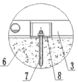
Fig. 5 is the II partial enlarged drawing that is fixedly connected with mechanism 5 among Fig. 3.
Fig. 6 is the III partial enlarged drawing that is fixedly connected with mechanism 5 among Fig. 3.
Fig. 7 is the main TV structure simplified schematic diagram of chemical bolt anchoring assembly 7.
Fig. 8 is the main TV structure simplified schematic diagram of Connection Block 8.
Fig. 9 is the left TV structure simplified schematic diagram of Fig. 8.
Figure 10 is Fig. 8 plan structure simplified schematic diagram.
Component title and sequence number among the figure:
The specific embodiment
Shown in Fig. 1~6, refuse transfer station equipment mounting process of the present invention comprises: 1. equipment Foundations unwrapping wire; 2. equipment Foundations are excavated; 3. installation of embedded parts; 4. concreting; 5. device location adjustment; 6. equipment is fixed, and the concrete technology step is:
1. equipment Foundations unwrapping wire: according to the refuse transfer station equipment installation drawing, put well equipment vertically, horizontal baseline;
2. equipment Foundations excavation: according to refuse transfer station equipment installation drawing and the equipment baseline put well, equipment Foundations are excavated, be backfilled to the absolute altitude of drawing requirement behind the excavation, and rammed earth.
3. installation of embedded parts: the built-in fitting that refuse transfer station equipment is required is installed according to the refuse transfer station equipment installation drawing.
4. concreting: according to refuse transfer station equipment installation drawing dimensional requirement formwork supporting plate in advance, check template size, concreting 6, maintenance concrete 6 is to strength grade.Concrete 6 is built only needs one-time-concreting, need not secondary and builds.
5. device location adjustment: according to the refuse transfer station equipment installation drawing, first equipment is placed in roughly shown position (referring to Fig. 1, Fig. 2), with survey tool device location is measured again, adopt special tool that the position of equipment is finely tuned, the requirement of device location size conforms installation drawing is finally guaranteed in so repeated measurement, fine setting.
6. equipment is fixed: adopt to be fixedly connected with mechanism's 5 syndetons installation, the described mechanism 5 that is fixedly connected with is chemical bolt anchor connection structures, described chemical bolt anchor connection structure comprises chemical bolt anchoring assembly 7 and Connection Block 8, during installation refuse transfer station 1 equipment is connected with concrete 6, chemical bolt anchoring assembly 7 is connected with Connection Block by nut 10 connections.
Referring to as shown in Figure 7, chemical bolt anchoring assembly 7 comprises screw rod 9, medicament pipe 12 and gel layer 13, and the inner chamber of screw rod 9 is drilled with the hole, and medicament pipe 12 is installed in the hole, and the skin of medicament pipe 12 is fixing by gel layer 13 bondings.
Referring to shown in Fig. 8~10, Connection Block 8 comprises riser 14, base plate 15 and stiffener 16, and riser 14 and base plate 15 are fixing by stiffener 16.
Chemical bolt anchor connection mode of the present invention includes but are not limited to the multiple connected modes such as expansion bolt connection, chemical anchoring connection.
Embodiment 1:
City, Nanning environmental sanitation place needs refuse transfer station equipment is installed, and adopts refuse transfer station equipment mounting process of the present invention.
Shown in Fig. 2,3,4 and 5, the equipment of this refuse transfer station 1 mainly comprises mobile flatcar 2, compressor 3 and loading bin 4, and the concrete technology that refuse storage area 1 equipment is installed is as follows:
1. equipment Foundations unwrapping wire: according to this model refuse transfer station equipment installation drawing, as calculated, setting-out determines the refuse transfer station equipment installation site, put well mobile flatcar 2, compressor 3 and loading bin 4 vertically, horizontal baselines.
2. equipment Foundations excavation: according to this model refuse transfer station equipment installation drawing and the equipment baseline put well, equipment Foundations are excavated, be backfilled to the absolute altitude of drawing requirement behind the excavation, and rammed earth.
3. installation of embedded parts: the built-in fitting that this model refuse transfer station equipment is required comprises built-in electric wire penetration pipe, hydralic hose penetration pipe, blow-off pipe and reinforcing bar etc. according to the installation of refuse transfer station equipment installation drawing.
4. concreting: in this model refuse transfer station equipment installation drawing, the installation dimension of mobile flatcar 2, compressor 3 and loading bin 4 requires to have propped up in advance template, checks template size, concreting, and maintenance concrete 6 is to strength grade.Concrete 6 is built only needs one-time-concreting, need not secondary and builds.
5. device location adjustment: according to this model refuse transfer station equipment installation drawing, first mobile flatcar 11, compressor 12 and loading bin 13 are placed in roughly shown position, with survey tool device location is measured again, and with special tool the position of mobile flatcar 11, compressor 12 and loading bin 13 is finely tuned, so repeated measurement, fine setting guarantee that finally mobile flatcar 11, compressor 12 and loading bin 13 position dimensions meet the installation drawing requirement.
6. equipment is fixed: adopt chemical bolt anchor connection mode, determine as calculated specification and the quantity of chemical bolt, be welded to connect seat 8, riser 14 and base plate 15 are welded and fixed by stiffener 16, in Connection Block 8 borings, pencil is placed in clear hole, screw in chemical bolt, by chemical bolt anchoring assembly 7 and Connection Block 8 mobile flatcar 2, compressor 3 and loading bin 4 are coupled together with concrete 6.
Claims (2)
1. refuse transfer station equipment mounting process, it is characterized in that: its mounting process comprises: 1) equipment Foundations unwrapping wire; 2) equipment Foundations excavation; 3) installation of embedded parts; 4) concreting; 5) device location adjustment; 6) equipment is fixed, and described concreting is one-time-concreting; The fixing chemical bolt anchor connection mode that adopts of described equipment, the concrete technology step is:
1) equipment Foundations unwrapping wire: according to the refuse transfer station equipment installation drawing, vertical, the horizontal baseline of the equipment of putting well;
2) equipment Foundations excavation: according to refuse transfer station equipment installation drawing and the equipment baseline put well, equipment Foundations are excavated, be backfilled to the absolute altitude of drawing requirement behind the excavation, and rammed earth;
3) installation of embedded parts: the built-in fitting that refuse transfer station equipment is required is installed according to the refuse transfer station equipment installation drawing;
4) concreting: prop up in advance template according to refuse transfer station equipment installation drawing dimensional requirement, checked template size, concreting, the maintenance concrete is to strength grade;
5) device location adjustment: according to the refuse transfer station equipment installation drawing, be placed in roughly equipment in the refuse storage area first, with survey tool device location is measured again, adopt special tool that the position of equipment is finely tuned, the requirement of device location size conforms installation drawing is finally guaranteed in so repeated measurement, fine setting;
6) equipment is fixed: adopt to be fixedly connected with mechanism (5) syndeton installation, the described mechanism 5 that is fixedly connected with is chemical bolt anchor connection structures, described chemical bolt anchor connection structure comprises chemical bolt anchoring assembly (7) and Connection Block (8), during installation refuse transfer station equipment is connected with concrete, chemical bolt anchoring assembly (7) is connected 8 with Connection Block) connect by nut (10).
2. refuse transfer station equipment mounting process according to claim 1, it is characterized in that: described chemical bolt anchoring assembly (7), comprise screw rod (9), medicament pipe (12) and gel layer (13), the inner chamber of screw rod (9) is drilled with the hole, medicament pipe (12) is installed in the hole, and the skin of medicament pipe (12) is fixing by gel layer (13) bonding.
3. the mounting process of refuse transfer station equipment according to claim 1, it is characterized in that: described Connection Block (8), comprise riser (14), base plate (15) and stiffener (16), riser (14) and base plate (15) are fixing by stiffener (16).
4. refuse transfer station equipment mounting process according to claim 3, it is characterized in that: described riser (14) and base plate (15) are to be made of steel plate materials.
Priority Applications (1)
| Application Number | Priority Date | Filing Date | Title |
|---|---|---|---|
| CN201210437774.1A CN102995654B (en) | 2012-11-06 | 2012-11-06 | Process for mounting equipment in garbage transportation station |
Applications Claiming Priority (1)
| Application Number | Priority Date | Filing Date | Title |
|---|---|---|---|
| CN201210437774.1A CN102995654B (en) | 2012-11-06 | 2012-11-06 | Process for mounting equipment in garbage transportation station |
Publications (2)
| Publication Number | Publication Date |
|---|---|
| CN102995654A true CN102995654A (en) | 2013-03-27 |
| CN102995654B CN102995654B (en) | 2015-01-07 |
Family
ID=47924710
Family Applications (1)
| Application Number | Title | Priority Date | Filing Date |
|---|---|---|---|
| CN201210437774.1A Active CN102995654B (en) | 2012-11-06 | 2012-11-06 | Process for mounting equipment in garbage transportation station |
Country Status (1)
| Country | Link |
|---|---|
| CN (1) | CN102995654B (en) |
Cited By (1)
| Publication number | Priority date | Publication date | Assignee | Title |
|---|---|---|---|---|
| CN110258617A (en) * | 2019-06-24 | 2019-09-20 | 中国二十二冶集团有限公司 | Construction method of precision grouting for equipment pad iron |
Citations (5)
| Publication number | Priority date | Publication date | Assignee | Title |
|---|---|---|---|---|
| JPH1060913A (en) * | 1996-08-14 | 1998-03-03 | Sumitomo Metal Ind Ltd | How to install machinery and equipment |
| JP2011094385A (en) * | 2009-10-29 | 2011-05-12 | Nippon Steel Corp | Method for replacing foundation bolt |
| CN102561712A (en) * | 2012-01-11 | 2012-07-11 | 中国建筑第二工程局有限公司 | Accurate positioning frame for large steel column and equipment foundation fixing bolt and construction method thereof |
| CN202391911U (en) * | 2012-01-04 | 2012-08-22 | 陈玉珍 | Chemical bolt |
| CN102704504A (en) * | 2012-06-26 | 2012-10-03 | 南通华新建工集团有限公司 | Method for constructing tower crane foundation |
-
2012
- 2012-11-06 CN CN201210437774.1A patent/CN102995654B/en active Active
Patent Citations (5)
| Publication number | Priority date | Publication date | Assignee | Title |
|---|---|---|---|---|
| JPH1060913A (en) * | 1996-08-14 | 1998-03-03 | Sumitomo Metal Ind Ltd | How to install machinery and equipment |
| JP2011094385A (en) * | 2009-10-29 | 2011-05-12 | Nippon Steel Corp | Method for replacing foundation bolt |
| CN202391911U (en) * | 2012-01-04 | 2012-08-22 | 陈玉珍 | Chemical bolt |
| CN102561712A (en) * | 2012-01-11 | 2012-07-11 | 中国建筑第二工程局有限公司 | Accurate positioning frame for large steel column and equipment foundation fixing bolt and construction method thereof |
| CN102704504A (en) * | 2012-06-26 | 2012-10-03 | 南通华新建工集团有限公司 | Method for constructing tower crane foundation |
Non-Patent Citations (1)
| Title |
|---|
| 李学衡: "混凝土设备基础施工方法探讨", 《中国新技术新产品》, no. 03, 10 February 2010 (2010-02-10), pages 98 - 99 * |
Cited By (1)
| Publication number | Priority date | Publication date | Assignee | Title |
|---|---|---|---|---|
| CN110258617A (en) * | 2019-06-24 | 2019-09-20 | 中国二十二冶集团有限公司 | Construction method of precision grouting for equipment pad iron |
Also Published As
| Publication number | Publication date |
|---|---|
| CN102995654B (en) | 2015-01-07 |
Similar Documents
| Publication | Publication Date | Title |
|---|---|---|
| CN102996148B (en) | High-ground-stress soft rock highway tunnel supporting method | |
| CN108842819B (en) | Urban rail transit cable line tunnel construction method | |
| CN104822884A (en) | Structural foundation | |
| CN106836829B (en) | A kind of mounting structure and its installation method of ring crane corbel | |
| CN103821520A (en) | Method for fixing mine vertical shaft device | |
| CN111254966A (en) | Bridge abutment and pier-column foundation structure in mountainous area and its construction method | |
| CN112832807A (en) | Supporting method and equipment for preventing roadway support from being severely damaged and surrounding rock from crossing and overflowing | |
| CN107165641B (en) | High inclination-angle ladder way opposite direction excavating construction method in thin layer breaking up hard rock stratum | |
| CN203716169U (en) | Portable tower crane foundation embedded formwork | |
| CN102995654B (en) | Process for mounting equipment in garbage transportation station | |
| JP2009057816A (en) | Method for correcting horizontal height of structure, equipment used in the method, and method for reinforcing bearing capacity of structure | |
| CN103061454A (en) | Locating method of installing concrete filled steel tubular column in underground deep hole | |
| CN102296600A (en) | Method for positioning middle pile of spread built subway station | |
| CN201588410U (en) | Automatic positioning device of steel pipe pillar | |
| CN204662373U (en) | A deformation monitoring devices that comes to nothing for panel rock-fill dam | |
| CN104631486A (en) | Independent plinth construction method in narrow environment | |
| CN103174155A (en) | Reverse construction method for erecting steel column and pouring concrete foundation later and steel support for construction | |
| CN109577999B (en) | Shield machine middle wind shaft reinforcing structure capable of preventing side wall deformation and shield machine planting head and construction method | |
| CN103174165A (en) | Full diameter embedded bolt positioning method | |
| CN102979529B (en) | Jacking device of tunnel measuring hole and construction method thereof | |
| CN215105392U (en) | Prefabricated retaining wall support structure of retractable artificial digging piles | |
| CN108505509A (en) | Skirt piles construction method for monitoring dyke earth horizontal displacement | |
| CN112177041B (en) | Underground space prefabricated and assembled integral structure and construction method thereof | |
| CN109577364A (en) | A kind of stacker-reclaimer track foundation construction method | |
| CN109594577A (en) | Prefabricated assembled bar shaped composite foundation mounting structure for soft soil foundation |
Legal Events
| Date | Code | Title | Description |
|---|---|---|---|
| C06 | Publication | ||
| PB01 | Publication | ||
| C10 | Entry into substantive examination | ||
| SE01 | Entry into force of request for substantive examination | ||
| C14 | Grant of patent or utility model | ||
| GR01 | Patent grant |