CN102995661A - Water meter chamber and water meter device thereof - Google Patents
Water meter chamber and water meter device thereof Download PDFInfo
- Publication number
- CN102995661A CN102995661A CN2012103974336A CN201210397433A CN102995661A CN 102995661 A CN102995661 A CN 102995661A CN 2012103974336 A CN2012103974336 A CN 2012103974336A CN 201210397433 A CN201210397433 A CN 201210397433A CN 102995661 A CN102995661 A CN 102995661A
- Authority
- CN
- China
- Prior art keywords
- water meter
- water
- derrick
- pipe
- outlet pipe
- Prior art date
- Legal status (The legal status is an assumption and is not a legal conclusion. Google has not performed a legal analysis and makes no representation as to the accuracy of the status listed.)
- Granted
Links
Images


Landscapes
- Measuring Volume Flow (AREA)
Abstract
一种水表井及其水表装置,水表井:由多根纵向立柱和多根横梁组成的上端开口的矩形水表井架,设置在水表井架的四个端角的钢筋水泥立柱,设置在水表井架顶端的钢筋水泥面板,形成在钢筋水泥面板中部的井盖,在位于水表井架底端内侧的横梁上设置有多个支架,在位于水表井架两侧的纵向立柱上与支架相对应处分别设置有支撑板,水表井架的外侧四周包裹有钢板封面,在位于两侧的支撑板侧的钢板封面上与支撑板的支撑处相对应的开有通孔。用于水表井的水表装置:通过连接管连接在水表进水侧的进水阀门,通过连接管连接在水表出水侧的出水阀门,进水阀门的另一端连接进水管,出水阀门的另一端通过伸缩件连接出水管。本发明结构简单,安装简便,实现了工厂化生产。
A water meter well and its water meter device, water meter well: a rectangular water meter derrick with an upper end opening composed of multiple longitudinal columns and a plurality of cross beams, reinforced concrete columns arranged at the four end corners of the water meter derrick, and a top of the water meter derrick Reinforced cement panel, the manhole cover formed in the middle of the reinforced concrete panel, a plurality of brackets are arranged on the crossbeam located inside the bottom end of the water meter derrick, and support plates are respectively arranged on the longitudinal columns on both sides of the water meter derrick corresponding to the brackets, A steel plate cover is wrapped around the outside of the water meter derrick, and a through hole is opened on the steel plate cover at the side of the support plate on both sides corresponding to the support of the support plate. Water meter device for water meter well: connect the water inlet valve on the water inlet side of the water meter through the connecting pipe, connect the outlet valve on the water outlet side of the water meter through the connecting pipe, the other end of the water inlet valve is connected to the water inlet pipe, and the other end of the outlet valve is passed through The telescopic piece is connected to the water outlet pipe. The invention has simple structure, easy and convenient installation, and realizes factory production.
Description
技术领域 technical field
本发明涉及一种水表安装结构。特别是涉及一种能够提高表井寿命的水表井及其水表装置。The invention relates to a water meter installation structure. In particular, it relates to a water meter well and a water meter device thereof which can improve the service life of the meter well.
背景技术 Background technique
随着无线网络技术和数字技术的发展,对供水设施的技术要求也越来越高,如对供水水表的控制已采用通过网络进行控制的智能式水表。因此,随着网络技术和数字技术用于水表控制,使得一些供水设施已经不适应智能式水表的使用。特别是目前普遍使用的水表井,大都是在地面挖坑,采用砖、水泥砌井,在水表井井体内穿连供水管,在供水管上装连水表、进水控制阀组成,但受其构造所限,水表井井体密封性差,水表中的电子器件易受潮损坏,不容易进行网络控制。这种结构的水表井易塌陷,影响了水表的使用寿命,而且现场进行砖、水泥砌井造成人力物力的消耗。With the development of wireless network technology and digital technology, the technical requirements for water supply facilities are getting higher and higher. For example, the control of water supply meters has adopted intelligent water meters controlled through the network. Therefore, with the use of network technology and digital technology for water meter control, some water supply facilities are no longer suitable for the use of smart water meters. Especially the water meter wells that are commonly used at present mostly dig pits on the ground, adopt bricks and cement to build wells, wear and connect water supply pipes in the water meter well wells, and install connected water meters and water inlet control valves on the water supply pipes. Due to the limitation, the sealing of the water meter well is poor, the electronic devices in the water meter are easily damaged by moisture, and it is not easy to carry out network control. The water meter well of this structure is easy to collapse, which affects the service life of the water meter, and the brick and cement well laying on the spot causes the consumption of manpower and material resources.
发明内容 Contents of the invention
本发明所要解决的技术问题是,提供一种可以提高水表井使用寿命和达到了防水防潮要求的水表井及其水表装置。The technical problem to be solved by the present invention is to provide a water meter well and its water meter device which can improve the service life of the water meter well and meet the requirements of waterproof and moisture-proof.
本发明所采用的技术方案是:一种水表井及其水表装置,水表井,包括:由多根纵向立柱和多根横梁组成的上端开口的矩形水表井架,设置在水表井架的四个端角的钢筋水泥立柱,设置在水表井架顶端的钢筋水泥面板,形成在钢筋水泥面板中部的井盖,在位于水表井架底端内侧的横梁上设置有用于支撑水表装置的多个支架,在位于水表井架两侧的纵向立柱上与所述的支架相对应处分别设置有用于支撑与水表的进水口和出水口对应连接的进水管和出水管的支撑板,所述的水表井架的外侧四周包裹有钢板封面,在位于两侧的支撑板侧的钢板封面上与支撑板的支撑处相对应的开有用于贯穿进水管和出水管的通孔。The technical solution adopted in the present invention is: a water meter well and its water meter device, and the water meter well includes: a rectangular water meter derrick with an upper end opening composed of a plurality of longitudinal columns and a plurality of cross beams, which is arranged at the four end corners of the water meter derrick The reinforced concrete column, the reinforced cement panel set on the top of the water meter derrick, the manhole cover formed in the middle of the reinforced cement panel, and the beams located inside the bottom of the water meter derrick are provided with multiple brackets for supporting the water meter device. On the longitudinal column on the side corresponding to the bracket, there are support plates for supporting the water inlet and outlet pipes correspondingly connected to the water inlet and outlet of the water meter, and the outside of the water meter derrick is wrapped with a steel plate cover , on the steel plate covers on the side of the support plate on both sides corresponding to the support of the support plate, there are through holes for penetrating the water inlet pipe and the water outlet pipe.
所述的支撑板的中部开有用于支撑且贯穿进水管和出水管的贯通孔。The middle part of the support plate is provided with a through hole for supporting and passing through the water inlet pipe and the water outlet pipe.
所述的井盖包括:盖体,一体形成在盖体的周边并径向向外凸出的边沿、形成在盖体内上部的电子仓以及盖在电子仓上面的电子仓盖,所述的电子仓的底端开有用于与水表井架内的水表装置进行连线的过线孔。The well cover includes: a cover body, an edge integrally formed on the periphery of the cover body and protruding radially outward, an electronic compartment formed on the upper part of the cover body, and an electronic compartment cover covered on the electronic compartment, the electronic compartment There is a wire hole for connecting with the water meter device in the water meter derrick at the bottom end of the water meter derrick.
所述的水表井架的底部设置有钢筋水泥底板。The bottom of the water meter derrick is provided with a reinforced concrete bottom plate.
一种用于水表井的水表装置,包括:水表,通过连接管连接在水表进水侧的进水阀门,通过连接管连接在水表出水侧的出水阀门,所述的进水阀门的另一端连接进水管,所述的出水阀门的另一端通过伸缩件连接出水管。A water meter device for a water meter well, comprising: a water meter, a water inlet valve connected to the water inlet side of the water meter through a connecting pipe, and a water outlet valve connected to the water outlet side of the water meter through a connecting pipe, and the other end of the water inlet valve is connected to The water inlet pipe, the other end of the water outlet valve is connected to the water outlet pipe through a telescopic piece.
所述的伸缩件包括有密封套管,可伸缩的插入在密封套管一端的伸缩管,所述的密封套管的另一端插入有出水管。The telescopic element includes a sealing sleeve, a telescopic tube that is telescopically inserted into one end of the sealing sleeve, and a water outlet pipe is inserted into the other end of the sealing sleeve.
所述的伸缩管的外管壁上形成有凹槽,所述的凹槽内嵌入有用于使所述的伸缩管与所述的密封套管的内周面密封结合的密封圈。A groove is formed on the outer wall of the telescopic tube, and a sealing ring for sealingly combining the telescopic tube with the inner peripheral surface of the sealing sleeve is embedded in the groove.
所述的出水管与密封套管通过焊接而固定连接。The water outlet pipe and the sealing sleeve are fixedly connected by welding.
所述的进水管和出水管分别依次贯穿水表井架中的支撑板和钢板封面伸出水表井架的外部。The water inlet pipe and the water outlet pipe successively pass through the support plate and the steel plate cover in the water meter derrick respectively and protrude from the outside of the water meter derrick.
本发明的水表井及其水表装置,结构简单,安装简便,实现了工厂化生产,解决了现场砖、水泥砌井的人力物力消耗,保护了环境,提高了表井寿命和达到了防水防潮的要求,满足网络控制的要求。本发明还具有如下特点:The water meter well and its water meter device of the present invention have simple structure and easy installation, realize factory production, solve the manpower and material resource consumption of on-site brick and cement well laying, protect the environment, improve the life of the meter well and achieve waterproof and moisture-proof effects Requirements to meet the requirements of network control. The present invention also has following characteristics:
1、表井采用四柱框架结构与金属板材料(塑料板)井体结合技术,有效地解决了整体结构的承重技术和整体表井的密封技术,同时实现了工厂化生产,提高了劳动生产率,解决了现场砌砖、浇注、抹灰施工带来的污染和浪费问题;1. The surface well adopts the combination technology of four-column frame structure and metal plate material (plastic plate) well body, which effectively solves the load-bearing technology of the overall structure and the sealing technology of the overall surface well, and at the same time realizes factory production and improves labor productivity. Solved the pollution and waste problems caused by on-site bricklaying, pouring and plastering construction;
2、表井的出口与水表阀门的连接采用“O”型圈密封的可伸缩管连接技术,解决了原水表、阀门与出水口紧连接造成的难以拆卸维修的问题,同时降低了拆卸水表的劳动强度;2. The connection between the outlet of the meter well and the water meter valve adopts the "O" ring-sealed telescopic pipe connection technology, which solves the problem of difficult disassembly and maintenance caused by the tight connection between the original water meter, valve and water outlet, and reduces the cost of dismantling the water meter. Labor intensity;
3、井盖采用钢、塑井盖设计,在井盖中心设计电子仓技术,解决了无线通讯的屏蔽问题,同时解决了电子件的安装和密封技术。3. The manhole cover is designed with steel and plastic manhole covers, and the electronic warehouse technology is designed in the center of the manhole cover, which solves the shielding problem of wireless communication, and at the same time solves the installation and sealing technology of electronic parts.
附图说明 Description of drawings
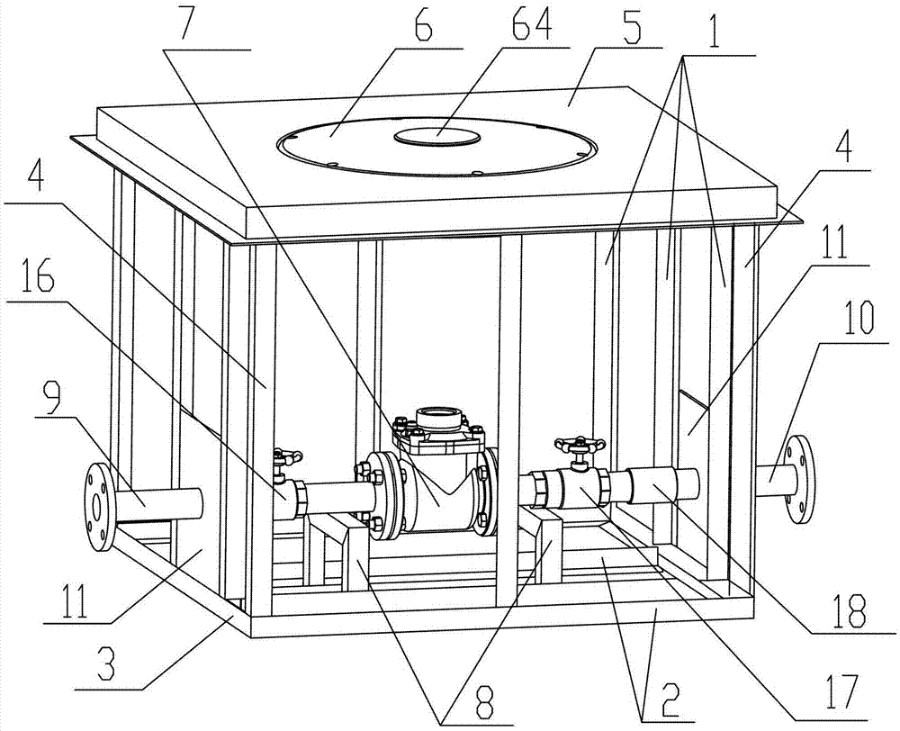
图1是本发明的内部结构示意图;Fig. 1 is a schematic diagram of the internal structure of the present invention;
图2是本发明的外部结构示意图;Fig. 2 is a schematic diagram of the external structure of the present invention;
图3是显示本发明中的钢筋水泥立柱的设置位置的示意图;Fig. 3 is the schematic diagram showing the setting position of reinforced concrete column among the present invention;
图4是本发明井盖的结构示意图;Fig. 4 is the structural representation of well cover of the present invention;
图5是本发明带有钢筋水泥底板的断面结构示意图;Fig. 5 is the cross-sectional structure schematic diagram that has reinforced concrete floor of the present invention;
图6是本发明伸缩件的结构示意图。Fig. 6 is a schematic structural view of the telescopic element of the present invention.
图中in the picture
1:纵向立柱 2:横梁1: Longitudinal column 2: Beam
3:水表井架 4:钢筋水泥立柱3: Water meter derrick 4: Reinforced cement column
5:钢筋水泥面板 6:井盖5: Reinforced cement panel 6: Manhole cover
61:盖体 62:边沿61: Cover body 62: Edge
63:电子仓 64:电子仓盖63: Electronic compartment 64: Electronic compartment cover
7:水表 8:支架7: Water meter 8: Bracket
9:进水管 10:出水管9: water inlet pipe 10: water outlet pipe
11:支撑板 12:钢板封面11: Support plate 12: Steel plate cover
13:通孔 14:贯通孔13: Through hole 14: Through hole
15:钢筋水泥底板 16:进水阀门15: Reinforced concrete floor 16: Water inlet valve
17:出水阀门 18:伸缩件17: Water outlet valve 18: Telescopic piece
181:密封套管 182:伸缩管181: Sealing sleeve 182: Telescopic tube
183:密封圈183: sealing ring
具体实施方式 Detailed ways
下面结合实施例和附图对本发明的水表井及其水表装置做出详细说明。The water meter well and its water meter device of the present invention will be described in detail below in conjunction with the embodiments and accompanying drawings.
如图1、图2、图3所示,本发明的水表井包括:由多根纵向立柱1和多根横梁2组成的上端开口的矩形水表井架3,设置在水表井架3的四个端角的钢筋水泥立柱4,设置在水表井架3顶端的钢筋水泥面板5,形成在钢筋水泥面板5中部的井盖6,所述的钢筋水泥立柱4设置在水表井架3的四个端角,解决了水表井架3的承重问题。在位于水表井架3底端内侧的横梁2上设置有用于支撑水表装置的多个支架8,如图所示,本实施例设置有两个支架8。在位于水表井架3两侧的纵向立柱1上与所述的支架8相对应处分别设置有用于支撑与水表7的进水口和出水口对应连接的进水管9和出水管10的支撑板11,所述的支撑板11的中部开有用于支撑且贯穿进水管9和出水管10的贯通孔14。所述的水表井架3的外侧四周包裹有钢板封面12,在位于两侧的支撑板11侧的钢板封面12上与支撑板11的支撑处相对应的开有用于贯穿进水管9和出水管10的通孔13。As shown in Fig. 1, Fig. 2 and Fig. 3, the water meter well of the present invention includes: a rectangular
如图5所示,所述的水表井架3的底部还设置有钢筋水泥底板15,起到防水防潮的作用。As shown in FIG. 5 , the bottom of the
如图4所示,所述的井盖6包括:盖体61,一体形成在盖体61的周边并径向向外凸出的边沿62、形成在盖体61内上部的电子仓63以及盖在电子仓63上面的电子仓盖64,所述的电子仓63的底端开有用于与水表井架3内的水表装置进行连线的过线孔(图中未示)。所述的井盖6采用塑料材料制作,所述的电子仓63内用于放置传输无线信号的电子器件,以及放置射频卡,便于读卡和电子器件的防水防潮。As shown in Figure 4, the well
如图1、图5所示,本发明的用于水表井的水表装置包括:水表7,通过连接管连接在水表7进水侧的进水阀门16,通过连接管连接在水表7出水侧的出水阀门17,所述的进水阀门16的另一端连接进水管9,所述的出水阀门17的另一端通过伸缩件18连接出水管10。As shown in Figures 1 and 5, the water meter device for water meter wells of the present invention includes: a
如图6所示,所述的伸缩件18包括有密封套管181,可伸缩的插入在密封套管181一端的伸缩管182,所述的密封套管181的另一端插入有出水管10。所述的伸缩管182的外管壁上形成有凹槽,所述的凹槽内嵌入有用于使所述的伸缩管182与所述的密封套管181的内周面密封结合的密封圈183,所述的密封圈183采用“O”型圈,解决了伸缩管182在伸缩时的防水问题。所述的出水管10与密封套管181通过焊接而固定连接。As shown in FIG. 6 , the
采用伸缩件18连接水表与出水管,解决了拆卸水表时的难度,降低了工程量。The
所述的进水管9和出水管10分别依次贯穿水表井架3中的支撑板11和钢板封面12伸出水表井架3的外部。并且所述的进水管9和出水管10是分别与水表井架3焊接。The
Claims (9)
Priority Applications (1)
| Application Number | Priority Date | Filing Date | Title |
|---|---|---|---|
| CN201210397433.6A CN102995661B (en) | 2012-10-18 | 2012-10-18 | Water meter chamber and water meter device thereof |
Applications Claiming Priority (1)
| Application Number | Priority Date | Filing Date | Title |
|---|---|---|---|
| CN201210397433.6A CN102995661B (en) | 2012-10-18 | 2012-10-18 | Water meter chamber and water meter device thereof |
Publications (2)
| Publication Number | Publication Date |
|---|---|
| CN102995661A true CN102995661A (en) | 2013-03-27 |
| CN102995661B CN102995661B (en) | 2015-01-14 |
Family
ID=47924717
Family Applications (1)
| Application Number | Title | Priority Date | Filing Date |
|---|---|---|---|
| CN201210397433.6A Expired - Fee Related CN102995661B (en) | 2012-10-18 | 2012-10-18 | Water meter chamber and water meter device thereof |
Country Status (1)
| Country | Link |
|---|---|
| CN (1) | CN102995661B (en) |
Cited By (4)
| Publication number | Priority date | Publication date | Assignee | Title |
|---|---|---|---|---|
| CN103669404A (en) * | 2013-12-26 | 2014-03-26 | 昆明普尔顿环保科技股份有限公司 | Plastic water meter well convenient to machine and use |
| JP2022085334A (en) * | 2020-11-27 | 2022-06-08 | 有限会社樋口水道 | Temporary faucet and its water supply temporary construction method |
| CN117344792A (en) * | 2023-12-04 | 2024-01-05 | 泊头市普惠仪表有限公司 | water meter protection well |
| US12613121B2 (en) | 2022-10-31 | 2026-04-28 | Logan POINDEXTER | Securement system for wireless water meter connected to hydrant |
Citations (8)
| Publication number | Priority date | Publication date | Assignee | Title |
|---|---|---|---|---|
| GB1170136A (en) * | 1967-04-17 | 1969-11-12 | John Kenneth Hoare | Improvements in or relating to Inspection Chambers. |
| US4637585A (en) * | 1985-04-15 | 1987-01-20 | Picollo August J | Reusable concrete curb inlet form |
| WO1995013172A1 (en) * | 1992-05-08 | 1995-05-18 | Quickcell Technology Pty. Ltd. | Method of manufacturing precast concrete units |
| CN2305658Y (en) * | 1997-02-27 | 1999-01-27 | 钟福喜 | Water meter chamber |
| CN2527825Y (en) * | 2002-03-29 | 2002-12-25 | 谢宏杰 | Pipeline expansion joint |
| CN2577257Y (en) * | 2002-11-19 | 2003-10-01 | 王强 | Water meter underground-box |
| CN201593195U (en) * | 2009-12-24 | 2010-09-29 | 平原县水务局 | Prefabricated water meter gate valve well |
| CN202881978U (en) * | 2012-10-18 | 2013-04-17 | 桑红旗 | Water meter well and water meter device of the same |
-
2012
- 2012-10-18 CN CN201210397433.6A patent/CN102995661B/en not_active Expired - Fee Related
Patent Citations (8)
| Publication number | Priority date | Publication date | Assignee | Title |
|---|---|---|---|---|
| GB1170136A (en) * | 1967-04-17 | 1969-11-12 | John Kenneth Hoare | Improvements in or relating to Inspection Chambers. |
| US4637585A (en) * | 1985-04-15 | 1987-01-20 | Picollo August J | Reusable concrete curb inlet form |
| WO1995013172A1 (en) * | 1992-05-08 | 1995-05-18 | Quickcell Technology Pty. Ltd. | Method of manufacturing precast concrete units |
| CN2305658Y (en) * | 1997-02-27 | 1999-01-27 | 钟福喜 | Water meter chamber |
| CN2527825Y (en) * | 2002-03-29 | 2002-12-25 | 谢宏杰 | Pipeline expansion joint |
| CN2577257Y (en) * | 2002-11-19 | 2003-10-01 | 王强 | Water meter underground-box |
| CN201593195U (en) * | 2009-12-24 | 2010-09-29 | 平原县水务局 | Prefabricated water meter gate valve well |
| CN202881978U (en) * | 2012-10-18 | 2013-04-17 | 桑红旗 | Water meter well and water meter device of the same |
Cited By (7)
| Publication number | Priority date | Publication date | Assignee | Title |
|---|---|---|---|---|
| CN103669404A (en) * | 2013-12-26 | 2014-03-26 | 昆明普尔顿环保科技股份有限公司 | Plastic water meter well convenient to machine and use |
| CN103669404B (en) * | 2013-12-26 | 2016-04-13 | 昆明普尔顿环保科技股份有限公司 | Process plastic water meter well easy to use |
| JP2022085334A (en) * | 2020-11-27 | 2022-06-08 | 有限会社樋口水道 | Temporary faucet and its water supply temporary construction method |
| JP7097425B2 (en) | 2020-11-27 | 2022-07-07 | 有限会社樋口水道 | Temporary faucet and its water supply temporary construction method |
| US12613121B2 (en) | 2022-10-31 | 2026-04-28 | Logan POINDEXTER | Securement system for wireless water meter connected to hydrant |
| CN117344792A (en) * | 2023-12-04 | 2024-01-05 | 泊头市普惠仪表有限公司 | water meter protection well |
| CN117344792B (en) * | 2023-12-04 | 2024-02-09 | 泊头市普惠仪表有限公司 | Water meter protection well |
Also Published As
| Publication number | Publication date |
|---|---|
| CN102995661B (en) | 2015-01-14 |
Similar Documents
| Publication | Publication Date | Title |
|---|---|---|
| CN102995661B (en) | Water meter chamber and water meter device thereof | |
| CN103835263A (en) | Prefabricated ditch | |
| CN106907163A (en) | A kind of shield tunnel ring intellectuality ruggedized construction and reinforcement means | |
| CN106558861A (en) | A kind of multi-functional cable ditch | |
| CN204418215U (en) | Prefabricated assembled manhole | |
| CN105350610B (en) | It is a kind of to be applied to the integrated pumping plant anti-floating system of fiberglass integral type | |
| CN202881978U (en) | Water meter well and water meter device of the same | |
| CN102322075B (en) | Enhanced reinforced plastic inspection well | |
| CN212582739U (en) | Prefabricated grout of concrete seals assembled inspection shaft | |
| CN205088086U (en) | Seamless package of prefabricated plate allies oneself with combination septic tank | |
| CN204753639U (en) | Prefabricated well of batch production modular concrete extrusion | |
| CN204983107U (en) | Assembly type rectangle open caisson | |
| CN202657916U (en) | Hanging basket weight balancing structure for external wall decoration and weight balancing water tank thereof | |
| CN204402019U (en) | Silo top heavy grade conical shell template system | |
| CN205205864U (en) | Concertina type inspection shaft | |
| CN209066493U (en) | A kind of pipeline configuration of pipeline disengaging basement | |
| CN209585120U (en) | A kind of prefabricated assembled lined with PVC sheets armored concrete anti-corrosion inspection shaft | |
| CN202831186U (en) | High-strength plastic inspection well | |
| CN202506274U (en) | Fast assembly type water film scrubber | |
| CN200940336Y (en) | Wire connection well | |
| CN204237691U (en) | Prefabrication type reinforced concrete septic tank | |
| CN217802399U (en) | Weighing sensor with moisture-proof structure for mortar tank | |
| CN205171554U (en) | Chute inspection shaft is inlayed to socket joint formula | |
| CN102943583A (en) | Method for constructing cast-in-situ steel concrete modular sewage treatment facility for town | |
| CN214940911U (en) | Prefabricated pump station of integration with antiseep function |
Legal Events
| Date | Code | Title | Description |
|---|---|---|---|
| C06 | Publication | ||
| PB01 | Publication | ||
| C10 | Entry into substantive examination | ||
| SE01 | Entry into force of request for substantive examination | ||
| C14 | Grant of patent or utility model | ||
| GR01 | Patent grant | ||
| CF01 | Termination of patent right due to non-payment of annual fee | ||
| CF01 | Termination of patent right due to non-payment of annual fee |
Granted publication date: 20150114 |