CN103003108A - Wiper device - Google Patents
Wiper device Download PDFInfo
- Publication number
- CN103003108A CN103003108A CN2011800369665A CN201180036966A CN103003108A CN 103003108 A CN103003108 A CN 103003108A CN 2011800369665 A CN2011800369665 A CN 2011800369665A CN 201180036966 A CN201180036966 A CN 201180036966A CN 103003108 A CN103003108 A CN 103003108A
- Authority
- CN
- China
- Prior art keywords
- wiper
- shaft
- wiper shaft
- drive motor
- sector section
- Prior art date
- Legal status (The legal status is an assumption and is not a legal conclusion. Google has not performed a legal analysis and makes no representation as to the accuracy of the status listed.)
- Granted
Links
Images
Classifications
-
- B—PERFORMING OPERATIONS; TRANSPORTING
- B60—VEHICLES IN GENERAL
- B60S—SERVICING, CLEANING, REPAIRING, SUPPORTING, LIFTING, OR MANOEUVRING OF VEHICLES, NOT OTHERWISE PROVIDED FOR
- B60S1/00—Cleaning of vehicles
- B60S1/02—Cleaning windscreens, windows or optical devices
- B60S1/04—Wipers or the like, e.g. scrapers
- B60S1/06—Wipers or the like, e.g. scrapers characterised by the drive
- B60S1/16—Means for transmitting drive
- B60S1/18—Means for transmitting drive mechanically
- B60S1/26—Means for transmitting drive mechanically by toothed gearing
-
- B—PERFORMING OPERATIONS; TRANSPORTING
- B60—VEHICLES IN GENERAL
- B60S—SERVICING, CLEANING, REPAIRING, SUPPORTING, LIFTING, OR MANOEUVRING OF VEHICLES, NOT OTHERWISE PROVIDED FOR
- B60S1/00—Cleaning of vehicles
- B60S1/02—Cleaning windscreens, windows or optical devices
- B60S1/04—Wipers or the like, e.g. scrapers
- B60S1/06—Wipers or the like, e.g. scrapers characterised by the drive
- B60S1/16—Means for transmitting drive
- B60S1/18—Means for transmitting drive mechanically
- B60S1/24—Means for transmitting drive mechanically by rotary cranks
Landscapes
- Engineering & Computer Science (AREA)
- Mechanical Engineering (AREA)
- Connection Of Motors, Electrical Generators, Mechanical Devices, And The Like (AREA)
- Gear Transmission (AREA)
- Transmission Devices (AREA)
- Jib Cranes (AREA)
Abstract
用于安装在机动车(105)中的雨刷装置(100),包括用于摆动地驱动雨刷臂的雨刷器轴(110)、可逆的驱动电机(155)和用于传递驱动电机的运动到雨刷器轴上的传递装置。所述传递装置具有设在雨刷器轴上的扇形齿段(120),在该扇形齿段中啮合有设在驱动电机上的齿轮或另一扇形齿段(135)。

A wiper assembly (100) for installation in a motor vehicle (105) includes a wiper shaft (110) for oscillatingly driving the wiper arm, a reversible drive motor (155), and a transmission device for transmitting the motion of the drive motor to the wiper shaft. The transmission device has a sector toothed section (120) on the wiper shaft, in which a gear or another sector toothed section (135) on the drive motor meshes.
Description
技术领域 technical field
本发明涉及一种具有权利要求1前序部分所述特征的雨刷装置。 The invention relates to a windshield wiping device having the features stated in the preamble of claim 1 .
背景技术 Background technique
雨刷装置例如在机动车上使用,用于在视野玻璃上导引雨刷片并且使视野玻璃没有污物和水分。在此由雨刷臂驱动雨刷片,雨刷臂围绕雨刷器轴往复摆动。为了摆动地驱动雨刷器轴已知许多不同的装置,它们尤其在复杂性和结构空间需求方面是不同的。 Windshield wiper devices are used, for example, in motor vehicles to guide a wiper blade over a windshield and to keep the windshield clear of dirt and moisture. The wiper blade is driven here by a wiper arm which pivots back and forth about a wiper shaft. Many different devices are known for the pivotal drive of the wiper shaft, which differ in particular with regard to their complexity and installation space requirement.
在常见的实施例中电动机利用耦连传动机构与雨刷器轴连接。与电动机的输出轴连接的第一曲轴通过推杆作用于与雨刷器轴连接的第二曲轴上,由此使电动机的输出轴的旋转运动转换成雨刷器轴的摆动运动。可以设有用于另一雨刷臂的另一雨刷器轴,它利用另一耦连传动机构通过雨刷器轴驱动。在此两个耦连传动机构的曲轴可以重合在雨刷器轴或输出轴上。在一种实施例中电动机设置在所述另一雨刷器轴的部位中,由此耦连传动机构将运动首先传递到更远离的雨刷器轴并且所述另一耦连传动机构从那里传递到较近的另外的雨刷器轴。 In typical exemplary embodiments, the electric motor is connected to the wiper shaft by means of a coupling drive. The first crankshaft connected to the output shaft of the motor acts on the second crankshaft connected to the wiper shaft through a push rod, thereby converting the rotational motion of the output shaft of the motor into the swing motion of the wiper shaft. A further wiper shaft can be provided for the other wiper arm, which is driven via the wiper shaft by means of a further coupling drive. In this case, the crankshafts of the two coupled transmissions can be superimposed on the wiper shaft or output shaft. In one embodiment, the electric motor is arranged in the region of the other wiper shaft, so that the coupling drive first transmits the motion to the further wiper shaft and from there to the further coupling drive Additional wiper shaft closer.
在此缺陷是,雨刷装置安装到机动车中所需的空间使最佳地相对于视野玻璃定位雨刷器轴是有问题的。尤其在机动车的前挡玻璃部位中使用雨刷装置时,雨刷器轴或所述另一雨刷器轴到前挡玻璃的侧面边界(A柱)的距离由于结构空间而相对较大,因此雨刷器(它利用雨刷臂与雨刷器轴连接)的雨刷范围在尺寸和/或位置上不是最佳的。因此本发明的目的是,给出雨刷装置,它具有减少的安装尺寸。 A disadvantage here is that the space required for the installation of the wiper device in the motor vehicle makes optimal positioning of the wiper shaft relative to the sight glass problematic. Especially when using a wiper device in the area of the windshield of a motor vehicle, the distance from the wiper shaft or the other wiper shaft to the side boundary (A-pillar) of the windshield is relatively large due to the installation space, so that the wiper (It utilizes the wiper arm to connect to the wiper shaft) The wiper range is not optimal in size and/or position. It is therefore the object of the present invention to provide a wiper device which has reduced installation dimensions.
发明内容 Contents of the invention
这个目的通过具有权利要求1特征的雨刷装置实现。从属权利要求给出优选的实施例。 This object is achieved by a windshield wiper device with the features of claim 1 . The dependent claims give preferred embodiments.
按照本发明的用于安装在机动车中的雨刷装置包括用于摆动地驱动雨刷臂的雨刷器轴、可逆的驱动电机和用于传递驱动电机的运动到雨刷器轴上的传递装置。所述传递装置具有设在雨刷器轴上的扇形齿段,在该扇形齿段中啮合有设在驱动电机上的齿轮或其它扇形齿段。 A wiper device according to the invention for installation in a motor vehicle comprises a wiper shaft for pivotally driving the wiper arm, a reversible drive motor and a transmission device for transmitting the movement of the drive motor to the wiper shaft. The transmission device has a tooth segment arranged on the wiper shaft, in which a gear wheel or another tooth segment arranged on the drive motor meshes.
由此可以使在雨刷器轴的背离驱动电机的一侧上所需的雨刷装置结构空间最小化。因此在利用雨刷臂与雨刷器轴连接的雨刷器的最佳雨刷效果的意义上,可以更好地定位雨刷器轴。 As a result, the installation space required for the wiper device on the side of the wiper shaft facing away from the drive motor can be minimized. A better positioning of the wiper shaft is thus possible in the sense of utilizing an optimum wiper effect of the wiper with the wiper arm connected to the wiper shaft.
所述雨刷装置可以具有另一雨刷器轴,用于摆动地驱动所述另一雨刷臂,其中所述雨刷器轴利用耦连传动机构相互连接。通过简单的、可靠的且经过考验的耦连传动机构可以使用用于驱动两个雨刷器的雨刷装置,如同在常见的机动车上所需的那样。可以通过适当地选择耦连传动机构的固定点来实现同向或反向地操纵雨刷器轴和所述另一雨刷器轴。 The wiper device can have a further wiper shaft for pivotally driving the further wiper arm, wherein the wiper shafts are connected to each other by means of a coupling drive. A simple, reliable and proven coupling drive makes it possible to use a wiper device for driving two wipers, as is required in conventional motor vehicles. Actuation of the wiper shaft and the further wiper shaft in the same direction or in opposite directions can be achieved by suitable selection of the fastening point of the coupling drive.
优选所述雨刷器轴设在机动车的司机侧的部位。由此可以提高司机侧的雨刷器的防脱落性。由此在驱动电机与机动车的电子控制系统和供电系统结合时,还可以得到优点。 Preferably, the wiper shaft is provided at a location on the driver's side of the motor vehicle. In this way, the anti-dropping performance of the windshield wiper on the driver's side can be improved. Advantages can thus also be obtained when the drive motor is integrated with the electronic control system and the power supply system of the motor vehicle.
在所述齿轮或另一扇形齿段上可以设置耦连传动机构的驱动元件。由此可以实现所述另一雨刷器轴相对于这个雨刷器轴的反向控制,无需在雨刷器轴或所述另一雨刷器轴的背离驱动电机的一侧上的附加结构空间。 A drive element of the coupling transmission can be arranged on the gear wheel or on the other tooth segment. As a result, a reverse control of the further wiper shaft relative to this wiper shaft can be achieved without requiring additional installation space on the wiper shaft or on that side of the further wiper shaft facing away from the drive motor.
所述扇形齿段可以具有比所述啮合在该扇形齿段中的齿轮或另一扇形齿段更大的作用半径。由此可以得到减速功能,由此使快速旋转的驱动电机以低的转矩适配于雨刷装置的要求。 The tooth segment can have a larger radius of action than the gear meshing in the tooth segment or the other tooth segment. This results in a reduction function, whereby the rapidly rotating drive motor can be adapted to the requirements of the wiper device with a low torque.
所述扇形齿段的齿部基于雨刷器轴可以形成角度,它小于约90°。由此可以避免,扇形齿段的部段在雨刷装置运行期间达到雨刷器轴的背离驱动电机的一侧上。由此可以节省其它结构空间并且提高雨刷器轴的最佳定位性。 The toothing of the tooth segment can form an angle relative to the wiper axis which is less than approximately 90°. This prevents a segment of the toothed segment from reaching that side of the wiper shaft facing away from the drive motor during operation of the wiper device. Additional installation space can thus be saved and optimal positioning of the wiper shaft can be increased.
所述驱动电机可以包括减速器。由此可以使用小型化的驱动电机,由此可以使所需的雨刷装置结构空间进一步减小。减速器可以是自锁的。 The driving motor may include a speed reducer. As a result, a miniaturized drive motor can be used, whereby the installation space required for the wiper device can be further reduced. The reducer can be self-locking.
可以设有固定元件,用于支承驱动电机和雨刷器轴,其中所述驱动电机到雨刷器轴的距离是可变化的。由此可以调节扇形齿段的齿部与齿轮或另一扇形齿段的齿部之间的间隙。由此利用雨刷臂与雨刷器轴连接的雨刷器可以更精确地定位。 A fastening element can be provided for supporting the drive motor and the wiper shaft, wherein the distance from the drive motor to the wiper shaft is variable. The play between the toothing of the tooth segment and the toothing of the gear wheel or another tooth segment can thus be adjusted. A more precise positioning of the wiper with the wiper arm connected to the wiper shaft can thus be achieved.
附图说明 Description of drawings
下面参阅附图详细解释本发明。附图中: The present invention is explained in detail below with reference to the accompanying drawings. In the attached picture:
图1示出雨刷装置, Figure 1 shows the wiper device,
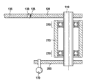
图2示出图1的雨刷装置的细节图。 FIG. 2 shows a detailed view of the wiper device from FIG. 1 .
具体实施方式 Detailed ways
图1示出用在机动车105上的雨刷装置100。雨刷装置100包括第一雨刷器轴110和第二雨刷器轴115。不受一般性限制,第一雨刷器轴110设置在司机侧,第二雨刷器轴115设置在机动车105的副驾驶侧。
FIG. 1 shows a windshield wiper device 100 for use on a motor vehicle 105 . The wiper device 100 includes a
扇形齿段120转矩锁合地与第一雨刷器轴110连接。扇形齿段120具有约90°的打开角并且在其径向外部部位载有齿部125。齿部125与另一扇形齿段135的齿部130啮合,另一扇形齿段转矩锁合地与减速器145的输出轴140连接。减速器145例如是自锁的蜗杆传动机构,由电动机150驱动并且与该电动机形成驱动电机155。
The
通过相应地电控制电动机150,在直流电机情况下例如通过适合地改变极性,可以使输出轴140在顺时针方向和逆时针方向上旋转,由此产生输出轴的摆动的旋转。在所示实施例中这样设计所述另一扇形齿段135的尺寸,使齿部130沿着围绕输出轴140的圆弧的长度接近于齿部120沿着围绕第一雨刷器轴110的圆弧的长度。尤其有意义的是,两个扇形齿段120和135具有相同的作用半径,即,齿部130与输出轴140的旋转轴线的距离等于齿部125与雨刷器轴110的旋转轴线的距离。
By correspondingly controlling the electric motor 150 , in the case of a direct current motor, for example by suitably changing the polarity, the output shaft 140 can be rotated in clockwise and counterclockwise directions, whereby an oscillating rotation of the output shaft is produced. In the exemplary embodiment shown, the
如果所述另一齿部135的作用半径小于扇形齿段120的作用半径,则通常打开角(所述另一扇形齿段135的齿部130基于输出轴140围成的角度)大于扇形齿段120的对应打开角。在一种实施例中,所述另一扇形齿段135的打开角为360°,从而是指以点划线表示的齿轮160。
If the active radius of the
耦连传动机构165传递第一雨刷器轴110的运动到第二雨刷器轴115上。为此,该耦连传动机构165包括第一球头销170(它设在扇形齿段120上)、第二球头销175(它设在转矩锁合地与第二雨刷器轴115连接的曲轴臂180上)和推杆185,它使第一球头销170与第二球头销175推拉稳定地连接。
Coupling gear 165 transmits the movement of
在所示实施例中第一雨刷器轴110和第二雨刷器轴115同向地控制,即,雨刷器轴110、115的旋转方向在雨刷装置100运行中指向相同的方向。
In the exemplary embodiment shown,
在另一种实施例中,第一球头销170也可以设在所述另一扇形齿段135或齿轮160上的以点划线所示的第一备选的位置190上。第一备选的位置190在图1中在垂直方向上位于扇形齿段120的齿部125与输出轴140之间,由此保持雨刷器轴110和115的操纵的同向性。
In a further exemplary embodiment, the
在另一种实施例中,第一球头销170设置在所述另一扇形齿段135或齿轮160上的第二备选的位置195上。第二可选择的位置195在图1中在垂直方向上位于输出轴140的背离扇形齿段120的齿部130的一侧上。由此与输出轴140同向地操纵第二雨刷器轴115。因为输出轴140由于相互啮合的齿部125和130总是与第一雨刷器轴110反向,第一雨刷器轴110和第二雨刷器轴115也反向地操纵。在所述另一扇形齿段135的情况下为了在第二备选的位置195支承第一球头销170,可以在第二备选的位置195与扇形齿段125之间构成相应的延长部(凸部)。
In another exemplary embodiment,
在另一未示出的实施例中还可以设有对应于雨刷器轴110和115的其它雨刷器轴,它们可以通过对应于耦连传动机构165的其它耦连传动机构控制。
In a further exemplary embodiment not shown, further wiper shafts corresponding to wiper
电动机150利用销栓196固定在装配板197上,其中销栓196容纳在长孔198中,所述长孔平行于输出轴140与雨刷器轴110之间的连接线延伸。在另一种实施例中长孔198也可以倾斜于这个连接线延伸。
Electric motor 150 is fastened to mounting plate 197 by means of pins 196 , wherein pins 196 are accommodated in slots 198 which extend parallel to the connecting line between output shaft 140 and
通过在长孔198中移动销栓196可以调整输出轴140与第一雨刷器轴110之间的距离。由此改变扇形齿段的齿部125与所述另一扇形齿段135或齿轮160的齿部130之间的间隙。通过减小输出轴140与第一雨刷器轴110之间的距离可以使齿部125与130之间的间隙减小到零,由此可以实现通过驱动电机115非常精确地控制第一雨刷器轴。在移动后,电动机利用销栓198通过过盈配合固定在装配板196上。在另一种实施例中第二雨刷器轴115也固定在装配板196上,由此得到可独立操纵的单元。
The distance between the output shaft 140 and the
雨刷装置100优选这样设计,在两个雨刷器轴110与115之间的连接线下方-除了雨刷器轴110和115本身和其支承结构以外-无需其它安装空间。在相应地设计或布置所示元件时,也可以使从第一雨刷器轴110向右和/或从第二雨刷器轴115向左的结构空间最小化。由此雨刷器轴110和115可以在机动车105中靠近边界安装。这些边界尤其可以是视野玻璃的边界,视野玻璃利用雨刷片和与雨刷器轴110、115连接的雨刷臂通过雨刷装置100清洁。边界还可以从视野玻璃的边框开始,例如从机动车105的所谓的A柱开始。
The wiper device 100 is preferably designed in such a way that no further installation space is required below the connecting line between the two
图2以另一种实施例示出图1的雨刷装置100的一部分的截面图。观察方向在图1中以剖面A-A给出。 FIG. 2 shows a section through a part of the windshield wiper device 100 from FIG. 1 in another exemplary embodiment. The viewing direction is given in FIG. 1 as section A-A.
雨刷器轴110在其上端部上与扇形齿段120连接。在其下端雨刷器轴110承载曲轴臂205,在曲轴臂上向下指向地固定第一球头销170。同样能够实现向上指向的固定。在扇形齿段120与曲轴臂205之间雨刷器轴110利用两个滚动轴承210可旋转地固定在雨刷器轴承外壳215上。雨刷器轴承外壳一般固定在视野玻璃的下面部位中。
The
在这个实施例中第二雨刷器轴115的旋转方向也与第一雨刷器轴110同向地延伸。
In this exemplary embodiment, the direction of rotation of the second wiper shaft 115 also extends in the same direction as the
Claims (8)
Applications Claiming Priority (3)
| Application Number | Priority Date | Filing Date | Title |
|---|---|---|---|
| DE201010038595 DE102010038595A1 (en) | 2010-07-29 | 2010-07-29 | wiper device |
| DE102010038595.6 | 2010-07-29 | ||
| PCT/EP2011/058890 WO2012013395A1 (en) | 2010-07-29 | 2011-05-31 | Wiper device |
Publications (2)
| Publication Number | Publication Date |
|---|---|
| CN103003108A true CN103003108A (en) | 2013-03-27 |
| CN103003108B CN103003108B (en) | 2016-01-20 |
Family
ID=44483900
Family Applications (1)
| Application Number | Title | Priority Date | Filing Date |
|---|---|---|---|
| CN201180036966.5A Expired - Fee Related CN103003108B (en) | 2010-07-29 | 2011-05-31 | Wiper system |
Country Status (5)
| Country | Link |
|---|---|
| EP (1) | EP2598383B1 (en) |
| CN (1) | CN103003108B (en) |
| BR (1) | BR112013002001A2 (en) |
| DE (1) | DE102010038595A1 (en) |
| WO (1) | WO2012013395A1 (en) |
Families Citing this family (2)
| Publication number | Priority date | Publication date | Assignee | Title |
|---|---|---|---|---|
| CN103481861A (en) * | 2013-09-05 | 2014-01-01 | 唐山轨道客车有限责任公司 | Electric window wiper for locomotives and high-speed trains |
| US11555752B2 (en) | 2020-02-12 | 2023-01-17 | Honda Motor Co., Ltd. | Systems and methods of verifying the assembly of a vehicle wiper assembly |
Citations (4)
| Publication number | Priority date | Publication date | Assignee | Title |
|---|---|---|---|---|
| WO2002006096A1 (en) * | 2000-07-19 | 2002-01-24 | Robert Bosch Gmbh | Windscreen wiper system comprising a tubular bearing rod |
| DE10306390A1 (en) * | 2003-02-15 | 2004-08-26 | Volkswagen Ag | Windscreen wiper system for vehicle has driven shaft of drive unit guided through wall of vehicle's body, and gear is installed on outer side of body, and with wiper shaft supporting wiper arm installed in region in front of windscreen |
| CN2642602Y (en) * | 2003-08-01 | 2004-09-22 | 蒋辉敏 | Windshield wiper capable of swinging to the angle of 180degree |
| CN201410933Y (en) * | 2009-04-30 | 2010-02-24 | 浙江关西电机有限公司 | car electric wiper |
Family Cites Families (5)
| Publication number | Priority date | Publication date | Assignee | Title |
|---|---|---|---|---|
| GB851276A (en) * | 1958-05-01 | 1960-10-12 | Gen Motors Ltd | Improvements in or relating to windscreen wiper systems |
| DE3237269A1 (en) * | 1982-10-08 | 1984-04-12 | SWF-Spezialfabrik für Autozubehör Gustav Rau GmbH, 7120 Bietigheim-Bissingen | Drive device, in particular for windscreen wipers on motor vehicles |
| DE10261926A1 (en) * | 2002-12-23 | 2004-07-01 | Robert Bosch Gmbh | Drive arrangement of a wiper device for windows of motor vehicles |
| DE10359968A1 (en) * | 2003-12-18 | 2005-07-21 | Valeo Systèmes d`Essuyage | wiper system |
| DE102009014312A1 (en) * | 2009-03-25 | 2010-09-30 | Valeo Systèmes d'Essuyage | Electromotive auxiliary drive, in particular wiper drive |
-
2010
- 2010-07-29 DE DE201010038595 patent/DE102010038595A1/en not_active Withdrawn
-
2011
- 2011-05-31 CN CN201180036966.5A patent/CN103003108B/en not_active Expired - Fee Related
- 2011-05-31 WO PCT/EP2011/058890 patent/WO2012013395A1/en not_active Ceased
- 2011-05-31 EP EP11725376.5A patent/EP2598383B1/en not_active Not-in-force
- 2011-05-31 BR BR112013002001A patent/BR112013002001A2/en not_active IP Right Cessation
Patent Citations (4)
| Publication number | Priority date | Publication date | Assignee | Title |
|---|---|---|---|---|
| WO2002006096A1 (en) * | 2000-07-19 | 2002-01-24 | Robert Bosch Gmbh | Windscreen wiper system comprising a tubular bearing rod |
| DE10306390A1 (en) * | 2003-02-15 | 2004-08-26 | Volkswagen Ag | Windscreen wiper system for vehicle has driven shaft of drive unit guided through wall of vehicle's body, and gear is installed on outer side of body, and with wiper shaft supporting wiper arm installed in region in front of windscreen |
| CN2642602Y (en) * | 2003-08-01 | 2004-09-22 | 蒋辉敏 | Windshield wiper capable of swinging to the angle of 180degree |
| CN201410933Y (en) * | 2009-04-30 | 2010-02-24 | 浙江关西电机有限公司 | car electric wiper |
Also Published As
| Publication number | Publication date |
|---|---|
| EP2598383B1 (en) | 2016-01-20 |
| WO2012013395A1 (en) | 2012-02-02 |
| BR112013002001A2 (en) | 2016-06-14 |
| EP2598383A1 (en) | 2013-06-05 |
| CN103003108B (en) | 2016-01-20 |
| DE102010038595A1 (en) | 2012-02-02 |
Similar Documents
| Publication | Publication Date | Title |
|---|---|---|
| JP6623763B2 (en) | Vehicle wiper device | |
| US7420346B2 (en) | Drive arrangement for a wiper device for windows of motor vehicles | |
| US8234745B2 (en) | Motor device and wiper apparatus | |
| JPH0146337B2 (en) | ||
| US5983439A (en) | Windshield wiper assembly having a variable speed drive mechanism | |
| KR101045772B1 (en) | How to adjust the wiping angle | |
| CN103003108A (en) | Wiper device | |
| CN101588947A (en) | wiper drive | |
| CN103228496A (en) | Window wiper device | |
| US20180229693A1 (en) | Drive device for driving the rotation of a wiper arm, particularly for a panoramic windscreen | |
| CN102177055A (en) | Drive device | |
| CN112977343B (en) | Wiper linkage system | |
| CN103249608B (en) | Window wiper device | |
| JP2019064555A (en) | Vehicular wiper device | |
| CN218703137U (en) | Windscreen wiper and vehicle with same | |
| CN104114416B (en) | Luffer boards windscreen-wiper drive | |
| CN104249709B (en) | Drive mechanism for windscreen wipers | |
| JP4878542B2 (en) | Vehicle wiper device | |
| JP4009393B2 (en) | Wiper device | |
| JP6972895B2 (en) | Vehicle wiper device | |
| KR20060092767A (en) | Rear wiper drive of car | |
| KR101135102B1 (en) | Driving device for a windshield wiper arrangement | |
| JP4377422B2 (en) | Wiper motor | |
| CN102874222A (en) | Drive unit for wiper device in vehicle | |
| CN104276141A (en) | Windscreen wiper system |
Legal Events
| Date | Code | Title | Description |
|---|---|---|---|
| C06 | Publication | ||
| PB01 | Publication | ||
| C10 | Entry into substantive examination | ||
| SE01 | Entry into force of request for substantive examination | ||
| C14 | Grant of patent or utility model | ||
| GR01 | Patent grant | ||
| CF01 | Termination of patent right due to non-payment of annual fee | ||
| CF01 | Termination of patent right due to non-payment of annual fee |
Granted publication date: 20160120 Termination date: 20180531 |