CN103016155A - 用于燃气涡轮入口冷却和湿压缩的超声水雾化系统 - Google Patents
用于燃气涡轮入口冷却和湿压缩的超声水雾化系统 Download PDFInfo
- Publication number
- CN103016155A CN103016155A CN2012103507269A CN201210350726A CN103016155A CN 103016155 A CN103016155 A CN 103016155A CN 2012103507269 A CN2012103507269 A CN 2012103507269A CN 201210350726 A CN201210350726 A CN 201210350726A CN 103016155 A CN103016155 A CN 103016155A
- Authority
- CN
- China
- Prior art keywords
- water
- ultrasonic water
- cooling system
- air cooling
- enters according
- Prior art date
- Legal status (The legal status is an assumption and is not a legal conclusion. Google has not performed a legal analysis and makes no representation as to the accuracy of the status listed.)
- Granted
Links
Images




Classifications
-
- F—MECHANICAL ENGINEERING; LIGHTING; HEATING; WEAPONS; BLASTING
- F02—COMBUSTION ENGINES; HOT-GAS OR COMBUSTION-PRODUCT ENGINE PLANTS
- F02C—GAS-TURBINE PLANTS; AIR INTAKES FOR JET-PROPULSION PLANTS; CONTROLLING FUEL SUPPLY IN AIR-BREATHING JET-PROPULSION PLANTS
- F02C7/00—Features, components parts, details or accessories, not provided for in, or of interest apart form groups F02C1/00 - F02C6/00; Air intakes for jet-propulsion plants
- F02C7/12—Cooling of plants
- F02C7/14—Cooling of plants of fluids in the plant, e.g. lubricant or fuel
- F02C7/141—Cooling of plants of fluids in the plant, e.g. lubricant or fuel of working fluid
- F02C7/143—Cooling of plants of fluids in the plant, e.g. lubricant or fuel of working fluid before or between the compressor stages
- F02C7/1435—Cooling of plants of fluids in the plant, e.g. lubricant or fuel of working fluid before or between the compressor stages by water injection
-
- B—PERFORMING OPERATIONS; TRANSPORTING
- B05—SPRAYING OR ATOMISING IN GENERAL; APPLYING FLUENT MATERIALS TO SURFACES, IN GENERAL
- B05B—SPRAYING APPARATUS; ATOMISING APPARATUS; NOZZLES
- B05B17/00—Apparatus for spraying or atomising liquids or other fluent materials, not covered by the preceding groups
- B05B17/04—Apparatus for spraying or atomising liquids or other fluent materials, not covered by the preceding groups operating with special methods
- B05B17/06—Apparatus for spraying or atomising liquids or other fluent materials, not covered by the preceding groups operating with special methods using ultrasonic or other kinds of vibrations
- B05B17/0607—Apparatus for spraying or atomising liquids or other fluent materials, not covered by the preceding groups operating with special methods using ultrasonic or other kinds of vibrations generated by electrical means, e.g. piezoelectric transducers
- B05B17/0615—Apparatus for spraying or atomising liquids or other fluent materials, not covered by the preceding groups operating with special methods using ultrasonic or other kinds of vibrations generated by electrical means, e.g. piezoelectric transducers spray being produced at the free surface of the liquid or other fluent material in a container and subjected to the vibrations
Landscapes
- Engineering & Computer Science (AREA)
- Chemical & Material Sciences (AREA)
- Combustion & Propulsion (AREA)
- Mechanical Engineering (AREA)
- General Engineering & Computer Science (AREA)
- Structures Of Non-Positive Displacement Pumps (AREA)
- Turbine Rotor Nozzle Sealing (AREA)
Abstract
本发明涉及用于燃气涡轮入口冷却和湿压缩的超声水雾化系统。具体而言,本发明提供了一种用于冷却燃气涡轮发动机(110)中的空气流(130)的进入空气冷却系统(100)。该进入空气冷却系统(100)可包括:入口过滤室(190);过渡件(200);入口导管(210);以及入口超声水雾化系统(300),其定位在入口过滤室(190)、过渡件(200)或入口导管(210)周围,以冷却空气流(130)。
Description
技术领域
本申请和所得专利大体上涉及燃气涡轮发动机,并且更特定而言涉及一种超声水雾化系统,该超声水雾化系统用于围绕燃气涡轮入口进行蒸发冷却以实现功率增大以及用于湿压缩而使压缩机叶片的侵蚀最小化。
背景技术
已知用于增加燃气涡轮发动机所能够产生的功率量的各种策略。一种增加燃气涡轮发动机的功率输出的方法是通过在压缩机中压缩进入空气之前冷却它。这种入口冷却导致空气具有更高的密度,从而形成进入压缩机中的更高质量流率。压缩机中的空气的更高质量流率允许更多的空气被压缩,从而允许燃气涡轮发动机产生更多功率。
一种类型的冷却系统包括潜在冷却或蒸发冷却。这种系统使用处于环境温度的水通过由于水蒸发而降低空气温度来冷却空气。这种系统的一个示例是基于介质的蒸发冷却器,其通过使水在板上或在腔室内的蜂窝状介质上行进且然后抽吸空气穿过腔室以使水蒸发而运行。蒸发冷却系统的另一个示例利用高压喷嘴喷射系统将水喷入空气中用于蒸发。蒸发冷却可将进入空气冷却到接近其湿球温度。蒸发冷却可为冷却进入空气的一种高效方法,因为与其它类型的入口冷却系统(例如线圈冷却系统等)相比,仅需要极少量的寄生功率来运行蒸发冷却系统。
另一种功率增大方法是湿压缩的使用。湿压缩通常包括将水滴喷射到压缩机的入口中。当气体和水的混合物被压缩时,气体的温度增加并且提供用于蒸发的驱动势。水的蒸发冷却气体,并因此通过减少压缩所需的功而增加可用功率。
关于公知的蒸发冷却系统的问题可包括与介质型蒸发冷却器有关的流动阻力。由介质型蒸发冷却器导致的到燃气涡轮入口空气流的典型压降可处于约0.25到约0.75英寸(约0.635到约1.9厘米)水柱的范围内。关于蒸发冷却和湿压缩的其它问题包括在水喷射蒸发冷却系统中发现的高的喷嘴磨损率,即,由通过喷射喷嘴的高速射流导致的高的喷嘴磨损率。另一个问题是需要昂贵的高压供水系统以供应高压蒸发冷却以及湿压缩喷射系统。此外,还存在来自蒸发冷却系统或湿压缩系统的未蒸发的大水滴进入压缩机并对压缩机叶片造成侵蚀或其它损坏的风险。
因此,存在着对于改进的燃气涡轮入口蒸发冷却系统以及湿压缩系统的需要。这样的系统可减少跨过其的压降,消除或避免喷嘴磨损,利用标准的低压供水系统,并且防止由未蒸发的大水滴对压缩机叶片的下游损坏。此外,这样的系统应当整体上提供功率增大而在燃气涡轮发动机上没有显著的寄生功率损失。与在仅仅使用介质型蒸发冷却的燃气涡轮中发现的那些相比,功率增大的收益较少受相对湿度高的环境条件限制。
发明内容
本申请和所得专利因此提供了一种用于冷却燃气涡轮发动机中的空气流的进入空气冷却系统。该进入空气冷却系统可包括:入口过滤室;过渡件;入口导管;以及入口超声水雾化系统,该入口超声水雾化系统定位在入口过滤室、过渡件或入口导管周围,以冷却空气流。
本申请和所得专利还提供了一种冷却用于燃气涡轮发动机的压缩机的进入空气流的方法。该方法可包括下列步骤:使一定体积的水在压缩机的上游雾化;形成细水雾;将细水雾混合到进入空气流中;利用细水雾冷却空气流;以及,使细水雾在到达压缩机之前基本蒸发。
本申请和所得专利还提供了一种用于减少燃气涡轮发动机的压缩机所需的功的湿压缩系统。该湿压缩系统可包括:入口过滤室;入口超声水雾化系统,其定位在入口过滤室周围;以及下游超声水雾化系统,其定位在压缩机周围。
对本领域普通技术人员而言,当结合若干附图和所附权利要求来回顾下面的详细描述时,本申请和所得专利的这些及其它的特征和改进将变得显而易见。
附图说明
图1是可如本文中所述的带有进入空气冷却系统的燃气涡轮发动机的示意图。
图2是可如本文中所述的超声水雾化系统的分解透视图。
图3A是图2的超声水雾化系统的侧视平面图。
图3B是带有备选盖的超声水雾化系统的侧视平面图。
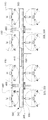
图4是带有超声水雾化系统的图1的进入空气冷却系统的入口过滤室的侧视平面图。
图5是带有超声水雾化系统的图1的进入空气冷却系统的入口过滤室的正视平面图。
图6是可如本文中所述的带有湿压缩的燃气涡轮发动机的示意图。
图7是可如本文中所述的下游超声水雾化系统的透视图。
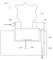
图8是图7的下游超声水雾化系统的侧视图。
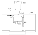
图9是可如本文中所述的下游超声水雾化系统的一备选实施例的侧视图。
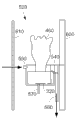
图10是可如本文中所述的下游超声水雾化系统的一备选实施例的侧视图。
附图标记:
100 进入空气冷却系统
110 燃气涡轮发动机
120 压缩机
130 空气流
140 燃烧器
150 燃料流
160 燃烧气体流
170 涡轮
180 天气罩(weatherhood)
190 入口过滤室
200 过渡件
210 入口导管
220 消声器
230 入口抽汽加热系统
240 屏
250 进气室
260 控制器
270 天气站
300 超声水雾化系统
310 泵装置(pump skid)
320 超声水雾化器
330 压电陶瓷超声雾化器
340 水箱
350 基部
360 盖
365 V形盖
370 孔口
380 水
390 空气间隙
400 供应线
410 溢漏口(overflow drain)
420 水流出线
430 过滤器安装板
440 过滤元件安装孔
460 细水雾
500 湿气压缩系统
510 两级超声水雾化系统
520 下游超声水雾化系统
530 喇叭口
540 井
550 供应线
560 溢漏口
570 动力线
580 竖直部件
590 水平部件
600 壁
610 板。
具体实施方式
现在参照附图,其中,遍及若干附图相似的标号表示相似的元件,图1显示了可如本文中所述的进入空气冷却系统100。该进入空气冷却系统100可与燃气涡轮发动机110一起使用。燃气涡轮发动机110可包括压缩机120。压缩机120压缩进入的空气流130。压缩机120将压缩的空气流130传送至燃烧器140。燃烧器将压缩的空气流130与加压的燃料流150混合并点燃该混合物而产生燃烧气体流160。燃烧气体流160继而被传送至涡轮170。燃烧气体流160驱动涡轮170,从而产生机械功。燃气涡轮发动机110可使用天然气、各种类型的合成气以及其它类型的燃料。燃气涡轮发动机110可为由纽约州斯卡奈塔第的通用电气公司等提供的许多不同的燃气涡轮发动机中的任何一种。在此可使用其它构件和其它配置。
进入空气冷却系统100可包括天气罩180,该天气罩180安装在入口过滤室190上,用于使进入的空气流130经过它。天气罩180可防止诸如雨、雪等天气元素进入其中。天气罩180和入口过滤室190可主要为常规设计。空气流130然后可流经过渡件200和入口导管210。在此还可使用消声器区段220和入口抽汽加热系统230。可使用一个或更多屏240来使较大类型的污染物或碎屑转向。空气流130然后可流过进气室250并进入压缩机120中用于压缩和燃烧,如上所述。在此可使用其它构件和其它配置。
进入空气冷却系统100和燃气涡轮发动机110的操作可由控制器260控制。控制器260可被规划为带有各种控制算法和其它类型的软件,以便操作和调节进入空气冷却系统100和燃气涡轮发动机110。在此可使用多个控制器260。控制器260可经由许多传感器确定到燃气涡轮发动机110的功率输出以及其它参数。同样,控制器260可能能够经由天气站270确定环境条件。天气站270可定位在入口过滤室190周围或其它位置。在此可适应许多不同类型的运行参数。在此可使用其它配置和其它构件。
进入空气冷却系统100还可包括入口超声水雾化系统300。如图1中所示,入口超声水雾化系统300可定位在入口过滤室190周围、过渡件200周围或者入口导管210周围。虽然显示了三(3)个不同的位置,但是在此可仅仅使用一(1)个位置。入口超声水雾化系统300可与泵装置310连通。泵装置310可在其中具有一定体积的水。该水可为去矿物质的、脱盐的等等。可在低压下(在大约150 psi下)供应该水。在此可使用其它类型的水源。
如图2中所示,入口超声水雾化系统300可在其中包括许多超声水雾化器320。具体而言,超声水雾化器320可为许多压电陶瓷超声雾化器330。压电陶瓷超声雾化器330依靠压电陶瓷振动来使水雾化。雾化的水可采取少于大约十(10)微米的一致的单位数微米尺寸的水滴的形式。这种尺寸一致的小水滴在减少潜在的压缩机叶片侵蚀等方面可能是有效的。
如图2和图3A中所示,超声水雾化系统包括许多水盘或水箱340。水箱340可具有任何期望的尺寸、形状或配置。水箱340可包括基部350。超声水雾化器320可定位在水箱340的基部350周围。水箱340还可在其上具有盖360。盖360可在其中具有许多孔口370。盖360的孔口370可与基部350的超声水雾化器320对准。一定体积的水380可定位在箱340内。空气间隙390可在水380和盖360之间延伸。水380的体积以及空气间隙390的广度可改变。进入水供应线400可定位在盖360周围。溢漏口410和水流出线420可定位在基部350周围。如图3B中所示,还可使用V形盖365。在此可使用其它构件和其它配置。
如图4和图5中所示,入口超声水雾化系统300可定位在入口过滤室190周围。其上定位有超声水雾化器320的许多水箱340可附连至过滤器安装板430或其它位置。(虽然图4中仅显示了一个水箱340,但可使用任何数量)。水箱340可定位在多个过滤元件安装孔440之后。水流出线420可与集水线或其它类型的流出线连通。如上所述,类似配置的入口超声水雾化系统300也可定位在过渡件200周围、入口导管210周围或者任何类型的内部支撑结构等周围。在此还可使用其它构件和其它配置。
在使用中,超声水雾化器320使水箱380内一定体积的水380振动而形成细水雾460。较大的水滴可能上升到水380的表面之上但不高到足以进入空气间隙390以至于通过孔口370逸出。较小滴的细水雾460由于浮力上升到水380的表面之上并通过空气间隙390和孔口370逸出。具体而言,细水雾460的滴比空气更轻且因此由于浮力而上升,与被注入空气流130中相反。这样,仅仅细水雾460出现在进入的空气流130并由其夹带。作为备选,空气流130中的细水雾可经由V形盖365被引导。
其中产生的细水雾460确保可接受的流率,同时防止较大的水滴进入空气流130并可能损坏压缩机叶片。此外,超声水雾化器320的使用提供了一种“故障保险”,因为,如果超声水雾化器320由于某种原因发生故障,结果将简单地为细水雾460的缺乏。这与可提供大水滴的喷射型喷嘴相反,如果进水压力由于某种原因减少或者如果喷嘴退化的话。这样的大水滴可导致下游损坏。
因此,入口超声水雾化系统300向细水雾460提供跨过其的可忽略压降,因为它具有不增加流路障碍的优势。在进入空气冷却系统110中水蒸发的使用有效地降低了进入空气流130的温度,并且因此允许更高的涡轮空气质量流用于功率增大。可基于功率输出需求、环境条件以及其它参数经由控制器260来控制水蒸发速率和整体液滴分布。
入口超声水雾化系统300可以以任何角度和流率传送细水雾460,从而增强其中的蒸发。此外,入口超声雾化系统300的特征为不能被释放到进入空气流130中并对压缩机造成下游损坏的完全保留的成分。入口超声水雾化系统300可为进入空气冷却系统100中的原始设备或者可为改型的一部分。
图6显示了可如本文中所述的湿压缩系统500。湿压缩系统500可使用两级超声水雾化系统510。具体而言,两级超声水雾化系统510可将入口超声水雾化系统300用作第一级并将下游的超声水雾化系统520用作第二级。在该示例中,入口超声水雾化系统300可定位在入口过滤室190或过渡件200周围。下游超声水雾化系统520可定位在进气室250周围或围绕压缩机20的喇叭口530周围。在此可使用其它位置。在此可使用其它构件和其它配置。
如图7和图8中的竖直部件剖面图中所示,下游超声水雾化系统520可使用呈井型布置540的许多超声水雾化器320。具体而言,压电超声水雾化器320可定位在井540中。井540可具有任何尺寸、形状或配置。虽然可在竖直部件580中使用盖360或开口,但为简单起见,图7和图8未示出盖。井540可包括供水线550和溢漏口560。还可使用动力线570。井540可如图7和图8所示安装在流路中的竖直部件580上,如图9所示安装在流路中的水平部件590上,如图10所示安装在壁600周围,或者其它位置。壁600可为任何类型的导管壁、底板等。在此还可使用屏或穿孔板610。在此可使用其它构件和其它配置。
在使用中,湿压缩系统500使用两级超声水雾化系统510。作为第一级,入口超声水雾化系统300提供细水雾460以经由蒸发冷却而冷却进入空气流130。细水雾460还使空气流130接近其饱和点。下游超声水雾化系统520然后将进一步细化的水雾460喷射到空气流130中。由于来自入口超声水雾化系统300的细水雾460接近饱和的事实,因而由下游超声水雾化系统520引入的细水雾460保持未蒸发并被带到压缩机120中。当空气130和细水雾460在压缩机120内被压缩时,温度和压力增加。因为夹带的水雾460,压缩热中的一些被水潜热吸收。因此,这种吸收减少了压缩机120的工作并提高了整体功率输出。
湿压缩系统500因此使用入口超声水雾化系统300用于冷却和功率增大(通过增加的质量流)并且使用下游超声雾化系统520用于中间冷却和减少压缩机120的工作。此外,在不干扰进入空气流130的情况下,下游超声水雾化系统520的构件可定位在入口框架内的任何位置。此外,下游超声水雾化系统520充当故障保险,因为大水滴将不会被喷射到压缩机120中从而对下游构件造成损坏。
应当显而易见的是,上述内容仅仅涉及本申请和所得专利的某些实施例。在不脱离由所附权利要求及其等同物所限定的本发明的一般精神和范围的情况下,本领域普通技术人员可在其中做出众多改变和修改。
Claims (15)
1.一种用于冷却燃气涡轮发动机(110)中的空气流(130)的进入空气冷却系统(100),包括:
入口过滤室(190);
过渡件(200);
入口导管(210);以及
入口超声水雾化系统(300),其定位在所述入口过滤室(200)、所述过渡件(200)或所述入口导管(210)周围,以冷却所述空气流(130)。
2.根据权利要求1所述的进入空气冷却系统(100),其特征在于,还包括与所述入口超声水雾化系统(300)连通的泵装置(310)。
3.根据权利要求1所述的进入空气冷却系统(100),其特征在于,所述入口超声水雾化系统(300)包括多个超声水雾化器(320)。
4.根据权利要求1所述的进入空气冷却系统(100),其特征在于,所述入口超声水雾化系统(300)包括多个压电陶瓷超声水雾化器(330)。
5.根据权利要求1所述的进入空气冷却系统(100),其特征在于,所述入口超声水雾化系统(300)包括其中带有一定体积的水(380)的水箱(340)。
6.根据权利要求5所述的进入空气冷却系统(100),其特征在于,所述水箱(340)包括其中带有一个或更多孔口(370)的盖(360),并且其中,所述一个或更多孔口(370)与一个或更多超声水雾化器(320)对准。
7.根据权利要求5所述的进入空气冷却系统(100),其特征在于,所述水箱(340)在其中包括空气间隙(390)。
8.根据权利要求5所述的进入空气冷却系统(100),其特征在于,所述水箱(340)包括溢漏口(410)。
9.根据权利要求5所述的进入空气冷却系统(100),其特征在于,所述水箱(340)包括V形盖(365)。
10.根据权利要求1所述的进入空气冷却系统(100),其特征在于,所述入口超声水雾化系统(300)产生细水雾(460)以冷却所述空气流(130)。
11.根据权利要求1所述的进入空气冷却系统(100),其特征在于,所述入口过滤室(190)包括过滤器安装板(430),并且其中,所述入口超声水雾化系统(300)被安装在所述过滤器安装板(430)上。
12.根据权利要求1所述的进入空气冷却系统(100),其特征在于,还包括下游超声水雾化系统(520)。
13.根据权利要求12所述的进入空气冷却系统(100),其特征在于,所述下游超声水雾化系统(520)包括井(540)。
14.根据权利要求12所述的进入空气冷却系统(100),其特征在于,所述下游超声水雾化系统(520)定位在进气室(250)或喇叭口(530)周围。
15.一种冷却用于燃气涡轮发动机(110)的压缩机(120)的进入空气流(130)的方法,包括:
使一定体积的水(380)在所述压缩机(120)的上游雾化;
形成细水雾(460);
将所述细水雾(460)喷射到所述进入空气流(130)中;
利用所述细水雾(460)冷却所述空气流(130);以及
使所述细水雾(460)在到达所述压缩机(120)之前基本蒸发。
Applications Claiming Priority (3)
| Application Number | Priority Date | Filing Date | Title |
|---|---|---|---|
| US13/236,712 | 2011-09-20 | ||
| US13/236712 | 2011-09-20 | ||
| US13/236,712 US9441542B2 (en) | 2011-09-20 | 2011-09-20 | Ultrasonic water atomization system for gas turbine inlet cooling and wet compression |
Publications (2)
| Publication Number | Publication Date |
|---|---|
| CN103016155A true CN103016155A (zh) | 2013-04-03 |
| CN103016155B CN103016155B (zh) | 2017-03-01 |
Family
ID=46924287
Family Applications (1)
| Application Number | Title | Priority Date | Filing Date |
|---|---|---|---|
| CN201210350726.9A Expired - Fee Related CN103016155B (zh) | 2011-09-20 | 2012-09-20 | 用于燃气涡轮入口冷却和湿压缩的超声水雾化系统 |
Country Status (3)
| Country | Link |
|---|---|
| US (1) | US9441542B2 (zh) |
| EP (1) | EP2573365A3 (zh) |
| CN (1) | CN103016155B (zh) |
Cited By (6)
| Publication number | Priority date | Publication date | Assignee | Title |
|---|---|---|---|---|
| CN103629153A (zh) * | 2013-10-09 | 2014-03-12 | 孙敏超 | 一种压缩空气的单级叶轮机械 |
| CN105169853A (zh) * | 2015-09-14 | 2015-12-23 | 中南大学 | 一种选矿厂筛分设备的除尘方法及其装置 |
| CN105764616A (zh) * | 2013-09-09 | 2016-07-13 | 奥姆纽斯特有限责任公司 | 喷雾装置 |
| TWI553219B (zh) * | 2013-10-23 | 2016-10-11 | Wen-Bin Chen | Internal combustion engine engine energy saving and pollution reduction atomization device |
| CN108506096A (zh) * | 2018-05-04 | 2018-09-07 | 西北工业大学 | 一种涡轮发动机射流预冷装置 |
| CN108580153A (zh) * | 2018-07-09 | 2018-09-28 | 中国船舶重工集团公司第七0三研究所 | 一种大流量超声精细雾化喷嘴 |
Families Citing this family (15)
| Publication number | Priority date | Publication date | Assignee | Title |
|---|---|---|---|---|
| US20140360217A1 (en) * | 2013-06-11 | 2014-12-11 | Bha Altair, Llc | Cooling system for use in a turbine assembly and method of assembly |
| US9492780B2 (en) | 2014-01-16 | 2016-11-15 | Bha Altair, Llc | Gas turbine inlet gas phase contaminant removal |
| US10502136B2 (en) | 2014-10-06 | 2019-12-10 | Bha Altair, Llc | Filtration system for use in a gas turbine engine assembly and method of assembling thereof |
| US10767561B2 (en) | 2014-10-10 | 2020-09-08 | Stellar Energy Americas, Inc. | Method and apparatus for cooling the ambient air at the inlet of gas combustion turbine generators |
| US9551282B2 (en) | 2014-10-17 | 2017-01-24 | General Electric Company | Media pads with mist elimination features |
| US9440353B1 (en) | 2014-12-29 | 2016-09-13 | Google Inc. | Offline determination of robot behavior |
| EP3109441B1 (en) * | 2015-06-24 | 2020-02-19 | Aaf Ltd. | System for reducing inlet air temperature of a device |
| JP7032015B2 (ja) | 2016-05-03 | 2022-03-08 | ゼネラル・エレクトリック・カンパニイ | 液体注入装置、および液体注入装置を有する圧縮機アセンブリ |
| WO2019075339A1 (en) * | 2017-10-12 | 2019-04-18 | Prodew, Inc. | HUMIDIFICATION SYSTEMS |
| WO2021130783A1 (en) * | 2019-12-26 | 2021-07-01 | Fazelzad Nima | System for increasing humidity of engine's inlet air |
| MX2023009883A (es) * | 2021-02-23 | 2023-11-09 | Stellar Energy Americas Inc | Sistemas de enfriamiento con entrada de aire de turbina con recuperacion de agua condensada. |
| US11773873B2 (en) | 2021-03-15 | 2023-10-03 | Air Products And Chemicals, Inc. | Process and apparatus for compressing hydrogen gas in a centrifugal compressor |
| US11926906B2 (en) | 2021-03-15 | 2024-03-12 | Air Products And Chemicals, Inc. | Process and apparatus for compressing hydrogen gas in a centrifugal compressor |
| US11453950B1 (en) | 2021-03-15 | 2022-09-27 | Air Products And Chemicals, Inc. | Method and apparatus for dosing hydrogen in a centrifugal compression system |
| CN114109608A (zh) * | 2021-11-29 | 2022-03-01 | 林胜杰 | 一种燃气轮机 |
Citations (7)
| Publication number | Priority date | Publication date | Assignee | Title |
|---|---|---|---|---|
| US4530464A (en) * | 1982-07-14 | 1985-07-23 | Matsushita Electric Industrial Co., Ltd. | Ultrasonic liquid ejecting unit and method for making same |
| US4731990A (en) * | 1985-07-30 | 1988-03-22 | Michael Munk | Internal combustion engine system and method with reduced noxious emissions |
| CN1092136A (zh) * | 1992-11-09 | 1994-09-14 | 奥马特工业有限公司 | 增大燃气轮机功率的方法及装置 |
| CN1612977A (zh) * | 2001-12-06 | 2005-05-04 | 阿尔斯通技术有限公司 | 在采用湿压缩的燃气涡轮中实现功率增大的方法和装置 |
| US20080157409A1 (en) * | 2004-03-23 | 2008-07-03 | Reens Daniel J | System and Method for Humidifying Homes and Commercial Sites |
| EP1365127B1 (en) * | 2002-05-16 | 2008-08-13 | ROLLS-ROYCE plc | Gas turbine engine and method of operating such a gas turbine engine |
| CN101936219A (zh) * | 2009-06-26 | 2011-01-05 | 燃气涡轮机效率瑞典公司 | 用于发动机的功率增大系统以及加湿空气的方法 |
Family Cites Families (66)
| Publication number | Priority date | Publication date | Assignee | Title |
|---|---|---|---|---|
| US4042016A (en) | 1975-10-28 | 1977-08-16 | Evelyn Boochever | Environmental humidification and cooling system |
| DE2931178A1 (de) * | 1979-08-01 | 1981-02-19 | Maschf Augsburg Nuernberg Ag | Gasturbinen-energiewandlungs-verfahren und vorrichtung zu seiner durchfuehrung |
| US4564375A (en) | 1983-07-18 | 1986-01-14 | Evelyn Munk | Humidification apparatus |
| US4731988A (en) * | 1985-07-30 | 1988-03-22 | Michael Munk | Internal combustion engine system and method with reduced noxious emissions |
| US4702074A (en) | 1985-07-30 | 1987-10-27 | Michael Munk | Internal combustion engine system with fog injection and heat exchange |
| US4773846A (en) | 1985-07-30 | 1988-09-27 | Michael Munk | Combustion system and method with fog injection and heat exchange |
| US4689895A (en) | 1986-02-28 | 1987-09-01 | Thermo Electron-Web Systems, Inc. | Evaporative-cooling apparatus and method for the control of web or web-production machine component surface temperatures |
| EP0275987A3 (en) | 1987-01-20 | 1989-07-26 | The Dow Chemical Company | Composition and method for cleaning gas turbine compressors |
| US4795683A (en) | 1987-07-23 | 1989-01-03 | United Technologies Corporation | High power density evaporatively cooled ion exchange membrane fuel cell |
| MY106055A (en) | 1988-01-27 | 1995-03-31 | Lrc Products | Polymeric casing with textured surface |
| CA1339055C (en) | 1988-09-09 | 1997-07-29 | Dean Arnold Ersfeld | Heat shrinkable bandage cover |
| NL8901348A (nl) | 1989-05-29 | 1990-12-17 | Turboconsult Bv | Werkwijze en inrichting voor het opwekken van electrische energie. |
| US5174130A (en) | 1990-03-14 | 1992-12-29 | Sonic Compressor Systems, Inc. | Refrigeration system having standing wave compressor |
| US5203161A (en) | 1990-10-30 | 1993-04-20 | Lehto John M | Method and arrangement for cooling air to gas turbine inlet |
| US5162291A (en) | 1991-06-10 | 1992-11-10 | Eastman Kodak Company | Solvent fusing of thermal printer dye image |
| US5282726A (en) | 1991-06-21 | 1994-02-01 | Praxair Technology, Inc. | Compressor supercharger with evaporative cooler |
| US5143754A (en) | 1991-08-01 | 1992-09-01 | Eastman Kodak Company | Solvent fusing of thermal printer dye image |
| US5353585A (en) | 1992-03-03 | 1994-10-11 | Michael Munk | Controlled fog injection for internal combustion system |
| JPH0624154A (ja) | 1992-07-08 | 1994-02-01 | I C I Japan Kk | 熱転写印刷用被転写体 |
| US5476555A (en) | 1992-08-31 | 1995-12-19 | Sps Technologies, Inc. | Nickel-cobalt based alloys |
| US5361450A (en) | 1992-12-31 | 1994-11-08 | Zellweger Uster, Inc. | Direct control of fiber testing or processing performance parameters by application of controlled, conditioned gas flows |
| JP2546765B2 (ja) | 1992-10-30 | 1996-10-23 | 鹿島建設株式会社 | 氷利用施設の製氷装置 |
| US5463873A (en) | 1993-12-06 | 1995-11-07 | Cool Fog Systems, Inc. | Method and apparatus for evaporative cooling of air leading to a gas turbine engine |
| US5523028A (en) * | 1995-01-05 | 1996-06-04 | Cool Fog Sysems, Inc. | Fogger bar assembly |
| JP3531677B2 (ja) | 1995-09-13 | 2004-05-31 | 株式会社東芝 | チタン合金製タービンブレードの製造方法およびチタン合金製タービンブレード |
| US5843214A (en) | 1995-10-31 | 1998-12-01 | California Energy Commission | Condensable vapor capture and recovery in industrial applications |
| US5867977A (en) | 1996-05-14 | 1999-02-09 | The Dow Chemical Company | Method and apparatus for achieving power augmentation in gas turbines via wet compression |
| JP3769827B2 (ja) | 1996-07-26 | 2006-04-26 | 石川島播磨重工業株式会社 | 湿り空気ガスタービン設備のインタークーラ切替制御装置 |
| JPH10238368A (ja) | 1996-10-12 | 1998-09-08 | Yoshihide Nakamura | コンバインドサイクルシステム |
| US6294842B1 (en) | 1997-12-19 | 2001-09-25 | Alliedsignal Inc. | Fog cycle for microturbine power generating system |
| US6173564B1 (en) | 1999-02-22 | 2001-01-16 | The Dow Chemical Company | Apparatus for monitoring wet compression gas turbine power augmentation-related casing distortions |
| US6250064B1 (en) | 1999-05-07 | 2001-06-26 | General Electric Co. | Gas turbine inlet air integrated water saturation and supersaturation system and related process |
| US6412291B1 (en) | 2000-09-05 | 2002-07-02 | Donald C. Erickson | Air compression improvement |
| US20020073712A1 (en) | 2000-10-19 | 2002-06-20 | Kopko William L. | Subatmospheric gas-turbine engine |
| US6553768B1 (en) | 2000-11-01 | 2003-04-29 | General Electric Company | Combined water-wash and wet-compression system for a gas turbine compressor and related method |
| US20020079783A1 (en) | 2000-12-22 | 2002-06-27 | Hopeck James Frederick | Air gap winding method and support structure for a superconducting generator and method for forming the same |
| US6715916B2 (en) * | 2001-02-08 | 2004-04-06 | General Electric Company | System and method for determining gas turbine firing and combustion reference temperatures having correction for water content in fuel |
| US6523346B1 (en) | 2001-11-02 | 2003-02-25 | Alstom (Switzerland) Ltd | Process for controlling the cooling air mass flow of a gas turbine set |
| US6880343B2 (en) | 2001-12-06 | 2005-04-19 | William L. Kopko | Supercharged gas turbine with improved control |
| GB2382847A (en) | 2001-12-06 | 2003-06-11 | Alstom | Gas turbine wet compression |
| USD511377S1 (en) | 2002-07-01 | 2005-11-08 | Donaldson Company, Inc. | Inlet air filter hood module for gas turbine systems |
| US6694766B1 (en) | 2002-08-21 | 2004-02-24 | Enlink Geoenergy Services, Inc. | Power generation systems with earth heat transfer |
| DE10256193A1 (de) | 2002-12-02 | 2004-06-09 | Alstom Technology Ltd | Verfahren zur Steuerung der Flüssigkeitseinspritzung in einen Zuströmkanal einer Kraft- oder Arbeitsmaschine |
| DE10311585A1 (de) | 2003-03-14 | 2004-09-23 | Basf Ag | Wirkstoffhaltige Adsorbate |
| EP1682750B1 (de) * | 2003-10-30 | 2012-11-28 | Alstom Technology Ltd | Kraftwerksanlage |
| US7767876B2 (en) | 2003-10-30 | 2010-08-03 | The Procter & Gamble Company | Disposable absorbent article having a visibly highlighted wetness sensation member |
| US6938405B2 (en) | 2003-11-13 | 2005-09-06 | General Electric Company | Spray nozzle grid configuration for gas turbine inlet misting system |
| CH697258B1 (de) | 2004-06-22 | 2008-07-31 | Alstom Technology Ltd | Verfahren zum Betrieb einer Gasturbine. |
| EP1914483A3 (en) | 2004-08-11 | 2008-07-09 | Lawrence Kates | Method and apparatus for monitoring refrigerant-cycle systems |
| JP2006084074A (ja) | 2004-09-15 | 2006-03-30 | Tlv Co Ltd | 減圧気化冷却装置 |
| JP2006084073A (ja) | 2004-09-15 | 2006-03-30 | Tlv Co Ltd | 減圧気化冷却装置 |
| CN100480488C (zh) | 2004-12-28 | 2009-04-22 | 蒋子刚 | 流体机械的揉动变容方法及其机构与用途 |
| US7454913B1 (en) * | 2005-04-29 | 2008-11-25 | Tassone Bruce A | Method and system for introducing fluid into an airstream |
| ES2275425B2 (es) | 2005-09-23 | 2007-11-16 | Universidad De Sevilla | Dispositivo neumatico para la produccion de un aerosol esterilizado mediante vaporizacion parcial. |
| US7703272B2 (en) | 2006-09-11 | 2010-04-27 | Gas Turbine Efficiency Sweden Ab | System and method for augmenting turbine power output |
| EP1923651A1 (en) | 2006-11-20 | 2008-05-21 | Donaldson Company, Inc. | A gas intake system |
| AT504618B1 (de) | 2006-12-05 | 2012-10-15 | Joanneum Res Forschungsgmbh | Verfahren zur herstellung von nanopartikeln und vorrichtung dazu |
| US20090320440A1 (en) | 2007-02-22 | 2009-12-31 | General Electric Company | Wet compression systems in turbine engines |
| JP2008286503A (ja) | 2007-05-21 | 2008-11-27 | Tokyo Univ Of Science | 沸騰冷却方法、沸騰冷却装置および機能製品 |
| US7810742B2 (en) * | 2007-05-21 | 2010-10-12 | Zvi Levi | Ultrasonic fog generator |
| US8601821B2 (en) | 2007-08-07 | 2013-12-10 | General Electric Company | Method and apparatus for supplying pressure for spray inlet temperature suppressor of gas turbines |
| KR20110005805A (ko) * | 2008-03-13 | 2011-01-19 | 보나도 에어, 엘엘씨 | 초음파 가습기 |
| US20100319384A1 (en) | 2009-06-19 | 2010-12-23 | General Electric Company | System for cooling gas turbine inlet air |
| US8196907B2 (en) | 2009-08-18 | 2012-06-12 | General Electric Company | System for conditioning the airflow entering a turbomachine |
| US20110173947A1 (en) | 2010-01-19 | 2011-07-21 | General Electric Company | System and method for gas turbine power augmentation |
| TWI458558B (zh) * | 2011-02-15 | 2014-11-01 | Micro Base Technology Corp | Spray holes and the use of its atomization module |
-
2011
- 2011-09-20 US US13/236,712 patent/US9441542B2/en not_active Expired - Fee Related
-
2012
- 2012-09-11 EP EP12183940.1A patent/EP2573365A3/en not_active Withdrawn
- 2012-09-20 CN CN201210350726.9A patent/CN103016155B/zh not_active Expired - Fee Related
Patent Citations (7)
| Publication number | Priority date | Publication date | Assignee | Title |
|---|---|---|---|---|
| US4530464A (en) * | 1982-07-14 | 1985-07-23 | Matsushita Electric Industrial Co., Ltd. | Ultrasonic liquid ejecting unit and method for making same |
| US4731990A (en) * | 1985-07-30 | 1988-03-22 | Michael Munk | Internal combustion engine system and method with reduced noxious emissions |
| CN1092136A (zh) * | 1992-11-09 | 1994-09-14 | 奥马特工业有限公司 | 增大燃气轮机功率的方法及装置 |
| CN1612977A (zh) * | 2001-12-06 | 2005-05-04 | 阿尔斯通技术有限公司 | 在采用湿压缩的燃气涡轮中实现功率增大的方法和装置 |
| EP1365127B1 (en) * | 2002-05-16 | 2008-08-13 | ROLLS-ROYCE plc | Gas turbine engine and method of operating such a gas turbine engine |
| US20080157409A1 (en) * | 2004-03-23 | 2008-07-03 | Reens Daniel J | System and Method for Humidifying Homes and Commercial Sites |
| CN101936219A (zh) * | 2009-06-26 | 2011-01-05 | 燃气涡轮机效率瑞典公司 | 用于发动机的功率增大系统以及加湿空气的方法 |
Cited By (8)
| Publication number | Priority date | Publication date | Assignee | Title |
|---|---|---|---|---|
| CN105764616A (zh) * | 2013-09-09 | 2016-07-13 | 奥姆纽斯特有限责任公司 | 喷雾装置 |
| CN103629153A (zh) * | 2013-10-09 | 2014-03-12 | 孙敏超 | 一种压缩空气的单级叶轮机械 |
| TWI553219B (zh) * | 2013-10-23 | 2016-10-11 | Wen-Bin Chen | Internal combustion engine engine energy saving and pollution reduction atomization device |
| CN105169853A (zh) * | 2015-09-14 | 2015-12-23 | 中南大学 | 一种选矿厂筛分设备的除尘方法及其装置 |
| CN108506096A (zh) * | 2018-05-04 | 2018-09-07 | 西北工业大学 | 一种涡轮发动机射流预冷装置 |
| CN108506096B (zh) * | 2018-05-04 | 2023-11-14 | 西北工业大学 | 一种涡轮发动机射流预冷装置 |
| CN108580153A (zh) * | 2018-07-09 | 2018-09-28 | 中国船舶重工集团公司第七0三研究所 | 一种大流量超声精细雾化喷嘴 |
| CN108580153B (zh) * | 2018-07-09 | 2024-04-09 | 中国船舶重工集团公司第七0三研究所 | 一种大流量超声精细雾化喷嘴 |
Also Published As
| Publication number | Publication date |
|---|---|
| US20130067922A1 (en) | 2013-03-21 |
| EP2573365A3 (en) | 2018-01-24 |
| US9441542B2 (en) | 2016-09-13 |
| CN103016155B (zh) | 2017-03-01 |
| EP2573365A2 (en) | 2013-03-27 |
Similar Documents
| Publication | Publication Date | Title |
|---|---|---|
| CN103016155B (zh) | 用于燃气涡轮入口冷却和湿压缩的超声水雾化系统 | |
| US7114910B2 (en) | Method and injection nozzle for interspersing a gas flow with liquid droplets | |
| CN102782411B (zh) | 用于涡轮机燃烧室的具有改善空气燃油混合物的喷气装置的喷射系统 | |
| ES2786301T3 (es) | Sistema para reducir la temperatura del aire de entrada de un dispositivo | |
| US8360711B2 (en) | Apparatus and method for pressurized inlet evaporative cooling of gas turbine engines | |
| JP2005511948A (ja) | 湿式圧縮を使用するガスタービンにおける動力増加を達成する方法と装置 | |
| JP5281044B2 (ja) | 噴霧システム、噴霧システムを備えるエンジンの動力増大システム、及び空気を加湿する方法 | |
| JP2005511947A5 (zh) | ||
| NO20052441L (no) | Fremgangsmate og apparat for rengjoring av en turbojetmotor | |
| JP2005511947A (ja) | 湿り圧縮を用いてガスタービンの動力を増大させる方法と装置 | |
| CN1219217A (zh) | 通过湿法加压在气体涡轮中获得功率增加的方法和装置 | |
| JP5716184B2 (ja) | 吸気冷却装置及びこれを備えたガスタービンプラント | |
| US7913936B2 (en) | Device for sound attenuation in a flow duct | |
| CN107448294B (zh) | 燃气涡轮机进气系统及其操作方法及燃气涡轮发动机 | |
| JP3502239B2 (ja) | ガスタービンプラント | |
| JP6221347B2 (ja) | 吸気冷却装置、ガスタービンプラント、及び吸気冷却方法 | |
| US20140360217A1 (en) | Cooling system for use in a turbine assembly and method of assembly | |
| JP2004132297A (ja) | 吸気冷却装置及び吸気冷却方法及びガスタービンプラント | |
| JP6221340B2 (ja) | 吸気冷却装置、ガスタービンプラント、及び吸気冷却方法 | |
| CN103867344A (zh) | 一种高加湿效率的柴油机进气加湿系统 | |
| JP6295774B2 (ja) | 吸気冷却装置、ガスタービンプラント、及び吸気冷却方法 | |
| JP2015010558A (ja) | ガスタービン用圧縮機の入口案内翼 | |
| KR101920156B1 (ko) | 흡입공기 냉각모듈 및 이를 이용한 가스터빈 흡입공기 냉각시스템 | |
| CN218431807U (zh) | 弥雾无人机 | |
| JP2019167887A (ja) | 吸気冷却装置および吸気冷却方法 |
Legal Events
| Date | Code | Title | Description |
|---|---|---|---|
| C06 | Publication | ||
| PB01 | Publication | ||
| C10 | Entry into substantive examination | ||
| SE01 | Entry into force of request for substantive examination | ||
| GR01 | Patent grant | ||
| GR01 | Patent grant | ||
| CF01 | Termination of patent right due to non-payment of annual fee | ||
| CF01 | Termination of patent right due to non-payment of annual fee |
Granted publication date: 20170301 Termination date: 20190920 |