CN103018698A - Protection of motor drive systems from current sensor faults - Google Patents
Protection of motor drive systems from current sensor faults Download PDFInfo
- Publication number
- CN103018698A CN103018698A CN2012103538214A CN201210353821A CN103018698A CN 103018698 A CN103018698 A CN 103018698A CN 2012103538214 A CN2012103538214 A CN 2012103538214A CN 201210353821 A CN201210353821 A CN 201210353821A CN 103018698 A CN103018698 A CN 103018698A
- Authority
- CN
- China
- Prior art keywords
- inn
- motor
- current
- phase
- instruction
- Prior art date
- Legal status (The legal status is an assumption and is not a legal conclusion. Google has not performed a legal analysis and makes no representation as to the accuracy of the status listed.)
- Granted
Links
Images
Classifications
-
- H—ELECTRICITY
- H02—GENERATION; CONVERSION OR DISTRIBUTION OF ELECTRIC POWER
- H02H—EMERGENCY PROTECTIVE CIRCUIT ARRANGEMENTS
- H02H7/00—Emergency protective circuit arrangements specially adapted for specific types of electric machines or apparatus or for sectionalised protection of cable or line systems, and effecting automatic switching in the event of an undesired change from normal working conditions
-
- H—ELECTRICITY
- H02—GENERATION; CONVERSION OR DISTRIBUTION OF ELECTRIC POWER
- H02P—CONTROL OR REGULATION OF ELECTRIC MOTORS, ELECTRIC GENERATORS OR DYNAMO-ELECTRIC CONVERTERS; CONTROLLING TRANSFORMERS, REACTORS OR CHOKE COILS
- H02P29/00—Arrangements for regulating or controlling electric motors, appropriate for both AC and DC motors
- H02P29/02—Providing protection against overload without automatic interruption of supply
- H02P29/024—Detecting a fault condition, e.g. short circuit, locked rotor, open circuit or loss of load
- H02P29/0243—Detecting a fault condition, e.g. short circuit, locked rotor, open circuit or loss of load the fault being a broken phase
-
- H—ELECTRICITY
- H02—GENERATION; CONVERSION OR DISTRIBUTION OF ELECTRIC POWER
- H02P—CONTROL OR REGULATION OF ELECTRIC MOTORS, ELECTRIC GENERATORS OR DYNAMO-ELECTRIC CONVERTERS; CONTROLLING TRANSFORMERS, REACTORS OR CHOKE COILS
- H02P21/00—Arrangements or methods for the control of electric machines by vector control, e.g. by control of field orientation
- H02P21/22—Current control, e.g. using a current control loop
-
- H—ELECTRICITY
- H02—GENERATION; CONVERSION OR DISTRIBUTION OF ELECTRIC POWER
- H02P—CONTROL OR REGULATION OF ELECTRIC MOTORS, ELECTRIC GENERATORS OR DYNAMO-ELECTRIC CONVERTERS; CONTROLLING TRANSFORMERS, REACTORS OR CHOKE COILS
- H02P29/00—Arrangements for regulating or controlling electric motors, appropriate for both AC and DC motors
- H02P29/02—Providing protection against overload without automatic interruption of supply
- H02P29/032—Preventing damage to the motor, e.g. setting individual current limits for different drive conditions
Landscapes
- Engineering & Computer Science (AREA)
- Power Engineering (AREA)
- Control Of Ac Motors In General (AREA)
Abstract
The invention relates to protection of motor drive systems from current sensor faults. Methods and apparatus are provided for detecting a phase current sensor fault in a multi-phase electrical motor. The method comprises, receiving an input torque command T* and measuring a set of feedback signals of the motor including a phase current Ix for each of the phases of the motor, generating direct and quadrature command phase currents Id*, Iq* for the motor corresponding to a value of the input torque command T*, determining a total command current Is=[(Iq*)2+(Id*)2] 1/2 , generating a negative sequence current Ineg, where for three phases Ineg=([1/3])[Ia+([alpha]2)Ib+([alpha])Ic], where [alpha]=ej2[pi]/3, combining Ineg and Is to provide a normalized negative sequence current Inn=Ineg/Is, comparing the normalized negative sequence current Inn to a predetermined threshold value INN* to determine the presence of a phase current sensor fault, and executing a control action when Inn>INN*.
Description
Technical field
The present invention relates generally to the emergency protection in the motor driven systems, and relates more specifically to the identification of electric machine phase current sensor fault and remedial action to stop or to alleviate damage to motor driven systems and parts thereof.
Background technology
Now, be widely used interchange (AC) electric system that is provided with electric power by direct current (DC) energy.The DC energy is that the motor propulsion system of the vehicle of accumulator is well-known.Fixed DC-AC motor propulsion system also is widely used.Control system monitoring and the control of using in this class propulsion system flows into each electric current mutually of polyphase machine.The current sensor that uses in this type systematic is not always as desired accurate, and perhaps, their degree of accuracy may change along with the time of system aging.The electric machine control system of prior art can not be distinguished normal operate miss and the error that is caused by current sensor faults.When sensor error or fault were undiscovered, system controller and/or propulsion electric machine itself can be damaged and system user may be under the unsafe conditions.
Therefore, expectation provides a kind of control system and method for improvement, for detection of the phase current sensor error that is caused by sensor fault, and in appropriate circumstances, takes remedial action.In addition, expectation be, for detection of this class sensor error and take the equipment of remedial action and method be simple, durable reliably and be suitable for transformation to existing system.In addition, other desirable factors and characteristics of the present invention will become obviously by detailed description subsequently and the claim of enclosing, with reference to accompanying drawing and aforesaid technical field and background technology.
Summary of the invention
Supplying method and equipment are for detection of phase current sensor (38) fault in the polyphase machine (26) and take suitable action.Receive or measure the input torque instruction T* (43) of motor (26) and the feedback signal group (60) of each the phase current Ix mutually that comprises motor (26), be that motor (26) generates direct sum orthogonal instruction phase current Id*, the Iq* corresponding to the value of input torque instruction T*, generate total instruction current Is=[(Iq*)
2+ (Id*)
2]
1/2, calculate negative-sequence current Ineg from the phase current that senses, herein, be Ineg=(1/3) [Ia+(α mutually for three
2) Ic of Ib+(α)], in the formula, α=e
J2 π/3, Ineg and Is unite provides standardized negative-sequence current Inn=Ineg/Is, this standardized negative-sequence current Inn and predetermined threshold INN* make comparisons to determine the existence of phase current sensor (38) fault, and at Inn〉and carry out control action during INN*.This control action can comprise following one or more, fault flag is set and/or diagnostic code is set to characterize the character of fault, and/or, reduce phase driving voltage Vx and/or phase exciting current Ix to prevent motor and/or the damage of other element of the propulsion system of the energy is provided to motor, and/or, provide soft or firmly close to minimize risk to anyone relevant with the propulsion system that comprises motor, material or technique.Embodiments of the invention can be retrofited for existing propulsion system.
The present invention also provides following scheme:
1. method for detection of the phase current sensor fault in the polyphase machine, the method comprises:
Receive the feedback signal group of motor that input torque instruction T* and measurement comprise the phase current Ix of each phase of motor;
Be direct sum orthogonal instruction phase current Id*, the Iq* of motor generation corresponding to the value of input torque instruction T*;
Determine total instruction current Is=f(Id*, Iq*);
Generation negative-sequence current Ineg=f(Ix);
Associating Ineg and Is are to provide standardized negative-sequence current Inn=Ineg/Is;
Standardized negative-sequence current Inn and predetermined threshold INN* are made comparisons to determine existing of phase current sensor fault; With
At Inn〉carry out control action during INN*.
2. such as scheme 1 described method, wherein, described control action is included in Inn〉fault flag is set during INN*.
3. such as scheme 2 described methods, wherein, described control action comprises the diagnostic code that the sign nature of trouble is set.
4. such as scheme 1 described method, wherein, described control action comprises, reduces the phase current Ix of flow direction motor.
5. such as scheme 1 described method, wherein, described control action comprises, reduces the phase voltage Vx that imposes on motor.
6. method for detection of the phase current sensor fault in the three phase electric machine, the method can be carried out by the electric machine controller that is suitable for controlling motor, and comprises:
Measure each the feedback signal group of motor of phase current Ia, Ib, Ic that input torque instruction T* and setting comprise three phases of motor, and use described controller;
Be direct sum orthogonal instruction phase current Id*, the Iq* of motor generation corresponding to the value of input torque instruction T*;
Determine total instruction current Is=[(Iq*)
2+ (Id*)
2]
1/2
Produce negative-sequence current Ineg=(1/3) [Ia+(α
2) Ic of Ib+(α)], α=e wherein
J2 π/3
Associating Ineg and Is are to provide standardized negative-sequence current Inn=Ineg/Is;
Standardized negative-sequence current Inn and predetermined threshold INN* are made comparisons to determine existing of phase current sensor fault; With
At Inn〉carry out control action during INN*.
7. such as scheme 6 described methods, comprise further, at Inn fault flag is set during INN*.
8. such as scheme 7 described methods, comprise further, the diagnostic code that characterizes nature of trouble also is set.
9. such as scheme 6 described methods, wherein, described control action comprises, reduces one or more in the phase current of flow direction motor.
10. such as scheme 6 described methods, wherein, described control action comprises, reduces voltage Va, the Vb, the Vc that impose on motor.
11. method that is not subjected to the fault effects of one or more current sensors for the protection of electric propulsion system; described current sensor measurement enters winding Wa, the Wb of drive motor, the phase current of Wc; described current sensor provides indication motor phase current signal Ia, Ib, Ic, and described method comprises:
Receive indication motor phase current signal Ia, Ib, Ic from described current sensor;
Receive motor torque command T* from the instruction input source;
Receive motor speed ω r from described motor;
Receive direct current (DC) voltage Vdc from the DC power supply that drive current is provided to described motor winding Wa, Wb, Wc;
Use T*, ω r and Vdc, obtain the value of time dependent d-axis instruction current Id* and orthogonal axes instruction current Iq*;
Determine total instruction current Is=[(Iq*)
2+ (Id*)
2]
1/2Value;
Determine negative-sequence current Ineg=(1/3) [Ia+α
2Ib+α Ic] value, wherein, α=e
J2 π/3
The value of the negative-sequence current Inn=Ineg/Is of settling the standard; With
Compare Inn and predetermined threshold INN*, and, if Inn〉INN*, just carry out control action.
12. such as scheme 11 described methods, comprise further, if Inn〉INN*, just reduce the drive current of flow direction motor winding Wa, Wb, Wc.
13. such as scheme 12 described methods, wherein, by voltage Vdc being changed into each winding Wa, not homophase A, three the time dependent voltage Va of B, C of Wb, Wc, Vb, the Vc that imposes on motor, acquisition is from the flow direction motor winding Wa in dc voltage source, the drive current of Wb, Wc, and wherein, reduce the drive current of flow direction motor winding Wa, Wb, Wc by reduction Va, Vb, Vc.
14. such as scheme 13 described methods, wherein, impose on the not homophase A of each motor winding Wa, Wb, Wc, three time dependent voltage Va, Vb, the Vc of B, C and depend on torque instruction T*, and, if Inn〉INN*, just cancel T* to reduce Va, Vb, Vc.
15. such as scheme 14 described methods, wherein, the throttle position that is activated by the operator at least in part derives described torque instruction T*.
16. such as scheme 11 described methods, comprise further, as Inn〉during INN*, carry out control action with step-up error mark in storer.
17. such as scheme 16 described methods, wherein, the step of carrying out control action is included in step-up error diagnostic code in the storer.
18. such as scheme 16 described methods, comprise further, as Inn〉during INN*, fault flag or indicator are set, then reduce phase voltage Va, Vb, Vc.
19. such as scheme 11 described methods, comprise further, as Inn〉during INN*, reduce the one or more phase currents that enter winding Wa, Wb, Wc.
20. such as scheme 11 described methods, comprise further, as Inn〉during INN*, close drive motor.
Description of drawings
Hereinafter will the present invention be described together with following figure, wherein, the element that identical digitized representation is identical, and
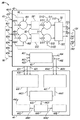
Fig. 1 illustrates typical DC-AC motor propulsion system, has used element well known in the prior art together with the element according to the embodiment of the invention work shown in Fig. 2 and 3;
Fig. 2 illustrates the signal shop drawing according to the embodiment of the invention, and how the controller of key drawing 1 works, and comprises the algorithm for detection of the sensor error in the propulsion system of Fig. 1 or fault; With
Fig. 3 is the process flow diagram according to another embodiment of the present invention, explains the method that is not subject to the damage that may be caused by these errors or fault for detection of the sensor fault in the propulsion system shown in Fig. 1 and 2 or error and protection system.
Embodiment
Following detailed description only is exemplary in essence and is not intended to limit the present invention or application of the present invention and use.In addition, be not intended to be subject to occur in aforementioned technical field, background technology, summary of the invention or the detailed description afterwards any clear and definite or the restriction that hint is theoretical.Current sensor faults can cause the great gain/offset error between the current sensor, and this causes that in current sensor three-phase is unbalance.In the situation of torque or Controlled in Current Mode and Based, these actual currents in mutually may be more much larger than current sensor.It is found that because the three-phase in the current sensor is unbalance, negative-sequence current occurs, this can be for the protection of system.
Fig. 1 illustrates typical DC-AC motor propulsion system 20,80, has used element well known in the prior art together with the element according to the embodiment of the invention work shown in Fig. 2 and 3.When the system of Fig. 1 during according to the algorithm shown in embodiment of the invention execution graph 2 and 3 and method, this system works by different way and obtains undiscovered result in the prior art.The agreement that adopts is, combination according to the prior art element of Fig. 1 of prior art work is regarded as " system 20 ", for example based on comprising prior art storer 33, " system 80 " regarded in the combination of the element of the different operating of but reprogramming similar some as, and it is carried out in mode shown in Fig. 2 and 3 according to the embodiment of the invention.For propulsion system 20,80 those common elements are discussed simultaneously.Propulsion system 20,80 comprises DC power supply 22, instruction input source 24, motor 26 and control system 28.Control system 28 receives: (i) for example the DC of accumulator can Vdc from DC power supply 22 via circuit 23,231, (ii) input (for example command torque T*) via circuit 25 from the instruction of instruction input source 24, and the running of electric power with control motor 26 is provided.Propulsion system 20,80 What fors are told in the instruction input of the customization in the input command source input 24, and for example, how motor 26 should turn round.
Control system 28 can be converted into the DC that receives from DC power supply 22 the AC energy and can flow to motor 26 to mutually suitable and big or small AC via circuit 37 in response to the input instruction (a plurality of) of receiving from input command source 24.For convenience of explanation, suppose that motor 26 is the three phase electric machines with motor phase A, B, C, but also can use with system 80 with other AC motor of more or less phase.Control system 28 comprises controller 30, driver module 34, power switching modules 36 and is respectively applied to mutually A, the B of motor 26 and current measurement device 38A, 38B, the 38C(of C is 38 together).Driver module 34 is traditional.Driver module 34 receives the phase control signal that controller 30 produces via bus 31, and ready, no matter may need any level to move, all above-mentioned drive control signal is changed into the level that is fit to power switching modules 36 usefulness, they are sent via circuit 35, for example, for phase A, via circuit 351, for phase B, via circuit 352, for phase C, via circuit 353.Above-mentioned phase control signal is also referred to as width modulation (PWM) signal.For three phase electric machine, power switching modules 36 generally includes six power switching apparatus (for example each has 2 mutually), and these power switching apparatus switch phase A, B, C at the reasonable time of being determined by the pwm signal of receiving from driver module 34 between the Vdc that partial reference voltage (for example motor) and DC power supply 23 provide.Power switching modules 36 provides respectively pulsion phase voltage Va, Vb, the Vc on motor phase A, B, C, for example, the phase voltage Va of motor phase A on circuit 371 is at the phase voltage Vb of the motor phase B on the circuit 372 and motor on the circuit 373 phase voltage Vc of C mutually.Above-mentioned power switching modules is well known in the art.
Propelling as required or the type of drive system, to have stipulated via circuit 25 from the input that the instruction of interface 24 input (a plurality of) can comprise, for example but be not intended to be limited to, wish the torque T* that motor 26 provides or wish that motor 26 provides to turn or the radian time per unit has the parameter of significant impact to propulsion system 20,80 use as the rotational speed omega r* of the motor 26 of unit or some other.For convenience of explanation but be not intended to limit, after this presumptive instruction input source 24 provides expectation torque instruction * to propulsion system 20,80.For convenience of description, asterisk being added on parameter or the variable to characterize above-mentioned variable or parameter is instruction or the reference value opposite with reality or measured value.For example, variable or parameter T* are used for characterizing expectation or command torque value, and are not used for characterizing actual torque value with variable or the parameter T of asterisk.Similarly, ω r* refers to the instruction rotor speed of motor 26, and ω r refers to the corresponding actual rotor rotating speed of motor 26.All follow in full this agreement.
Current sensor 38A, 38B, 38C(are 38 jointly) measure that mutually A, B, electric current I a, the Ib of C, the Ic(of flow direction motors 26 are Ix jointly respectively via power switching modules 36 and circuit 37 from DC power supply 22).The signal that represents these measured values for example, represents the measured value of Ia on circuit 391 via circuit 39 controller 30 of feeding, and represents the measured value of Ib on circuit 392, represents the measured value of Ic on circuit 393.Yet the personnel skilled to this area will understand that they are not the real currents of flow direction controller 30 in the circuit 39, and only be to characterize current through line in fact 37 to the signal of the size of real current Ia, the Ib of motor 26, Ic.Usually or jointly, term Ix is used for referring to phase current, term Vx is used for referring to phase voltage (and signal represents above-mentioned phase current or voltage), and wherein, x adopts the value that is suitable in the number of motor phases of using.For example, for the two-phase machine, x will adopt two values (for example, a, b), be three values (for example, a, b, c) for three-phase machine, be six values for six phase machines, and will be like that.
Controller 30 has input/output interface (I/O) parts 301-306, processor 32 and storer 33,33 '.Storer 33 is used for referring to control according to the storer of the operation of the system 20 of prior art operation, and storer 33' is used for referring to control according to the storer of the operation of the system 80 of Fig. 2-3 operation.Processor 32 can be a plurality of accurate independent processor of uniprocessor, polycaryon processor or the calculated load of sharing controller 30.I/O interface unit 301-306 communicates by letter with processor 32 via circuit or bus 3011,3021,3031,3041,3051,3061 respectively.Input interface parts 301 receive for example from the T* input of instruction input source 24 via circuit or bus 25.Input interface parts 302 receive Vdc via circuit or bus 23 and 231 from DC power supply 22.Input interface parts 302 receive the signal that represents Ia, Ib and Ic from current sensor 38A, 38B, 38C respectively on circuit or bus 39.Input interface parts 304 receive rotor angle information θ r via circuit or bus 261 from motor 26.Input interface parts 304 receive rotor angle information via circuit or bus 261 from motor 26.Input interface parts 305 receive rotor speed information ω r via circuit or bus 262 from motor 26.301-305 is ready for the input interface parts, no matter may need what level to move or other signal operation, all makes above-mentioned information and processor 32 compatibilities.Output interface unit 306 receives motor phase actuated signal via circuit or bus 3061 from processor 32, and ready, no matter may need any level to move or other signal operation, all make above-mentioned instruction useful via circuit or 31 pairs of driver modules 34 of bus.Storer 33,33' and processor are connected by circuit or bus 331 connections.For convenience of explanation, processor 32 is connected with storer, 33' is shown the independent component that is connected by circuit 331 in Fig. 1, but in other embodiments, they can merge.Arbitrary layout is all available.In one embodiment of the invention; the feedback information that controller 30 receives about Vdc, Ia, Ib, Ic, θ r and ω r; with this information be stored among the storer 33' about the information combination of the character of propulsion system 80 and use together with what Fig. 2-3 described and also be stored in expediently algorithm among the storer 33', detect and sensor error or fault whether have occurred and taked suitably action not to be damaged with warning system user and/or protection propulsion system 80.Although the major part of the propulsion system 20 that Fig. 1 describes, 80 independent component may be out-of-date in the technology, but, system 80 and method 800 that said elements and the combination of describing and for example be stored in the algorithm in storer 33' or other places together with Fig. 2-3 provide is new, improved can the detecting sensor faults and take remedial action.
Fig. 2 illustrates sketch 40, with controller function Figure 42 and algorithm 44.How the controller 30 of function Figure 42 key drawing 1 produces on present bus or the circuit 31 to the signal of driver module 34 and finally makes power switching modules 36 provide voltage Va, Vb, Vc and electric current I a, Ib, Ic to phase A, B, the C of the motor 26 of Fig. 1.Algorithm 44 makes controller 30 can detect current sensor error or the fault in the propulsion system 80 of Fig. 1 and takes remedial action.
Polyphase machine can be said into the mode of mathematics has two magnetic symmetry axles, that is, d-axis (d) and orthogonal axes (q), this will be that those of ordinary skills understand.The work of above-mentioned polyphase machine can be with being adjusted to provide d-axis stator flux does ψ
d*, ψ
dCorresponding direct-axis current Id*, Id and be adjusted to the quadrature current of quadrature stator flux does ψ be provided
q*, ψ
qQuadrature current Iq*, Iq represent at this, as previously mentioned, the sign command quantity of * is arranged, do not have the actual or amount of recording of sign of *, Id and Iq for example represent with equation:
Id=(2/3) [(Ia) (cos θ r)+(Ib) (cos (θ r-2 π/3))+(Ic) (cos (θ r+2 π/3))] equation 1
Iq=(2/3) [(Ia) (sin θ r)+(Ib) (sin (θ r-2 π/3))+(Ic) (sin (θ r+2 π/3))] equation 2
In the formula, θ r is rotor angle.If use is actual or record electric current I a, Ib, Ic and rotor angle r, the result just provides Id and Iq(namely not to have *), if use instruction current Ia*, Ib*, Ic* and rotor angle r, the result just provides Id* and Iq*.In practice, the physical relation between T, Vdc, ω r and Ia, Ib, the Ic is definite by testing, calculate Id and Iq and be placed in the question blank for example or its equivalent at storer for example in the memory bank 33,33' of Fig. 1.So, shown in the frame 46 of Fig. 2, for input instruction 43(T* for example), any given combination of Vdc and ω r, just can determine Id* and Iq* from question blank.
The part 48 that function Figure 42 comprises has: (i) combiner 491,492(are 49 jointly), they receive input Iq*, the input Iq on the wire 4912, the input Id* on the wire 4921 and the input Id* on the wire 4922 on the wire 4911; (ii) proportional integral (PI) controller 501,502(are 50 jointly), they are connected respectively to the output of combiner 49; (iii) combiner 511,512(are 51 jointly), they receive the output of PI controllers 50 at wire 5111 and 5121, and at wire 5112 input { (ω
r) (ψ
d*)+(Iq
*) (Rs) and at wire 5122 input { (ω
r) (ψ
q*)+(Id
*) (Rs), in the formula, Rs is the stator resistance of motor 26; (iv) d, q – a, b, c converter 52, its receiving combinator 511,512 output, the input ω on the wire 521
rWith the input θ r on the wire 522, and be created in output 523 places signal Va*, output 524 places signal Vb* and output 525 places signal Vc*, thereby obtain seeing Fig. 1 at circuit or bus 31() on signal, be enough to produce Va, Vb on the circuit 37, Vc so that electric current I a, Ib, Ic phase A, B, C to motor 26 to be provided in output place of power switching modules 36.Width modulation (PWM) signal Da, signal Db and the signal Dc(at output 543 places at output 542 places that another road part 42 of the regulation of controller 30 is provided at output 541 places are 54 jointly), these produce Va, Vb, Vc at phase A, B, the C of motor 26 when the power switching modules 36 of the Fig. 1 that feeds by driver module 34.
Give and to record rotor speed ω in voltage Vdc that the feedback signal 60 of controller 30 can comprise phase current signal Ia, the phase current signal Ib in the input 602 in the input 601, the phase current signal Ic in the input 603, the dc voltage shown in Figure 1 source 22 in the input 604, the input 605
rWith the rotor angle that records in the input 606
rTherefore, other signal that controller 30 is processed can comprise the d-axis stator flux does (ψ d*) of the motor 26 of Fig. 1 and quadrature stator flux does (ψ q*) with and (Rs), these values can be stored in the storer 33,33' of Fig. 1 or be calculated at an easy rate by the data about motor 26 that processor 32 bases are stored among storer 33, the 33'.Shown in the part 48 of sketch 40, controller 30 is suitable for processing signals 43 and 60 to produce phase voltage Va, Vb and the Vc of the control that is used for motor 26.
Controller 30 also uses other traditional AC Electric Machine Control variable.To understand well as those of ordinary skills, voltage and current can be expressed as the vector on the d-q coordinate system.Therefore, controller 30 is suitable for determining that current instruction value Id*, Iq* namely offer the electric current of corresponding d axle and q axle and voltage instruction value Vd*, Vq* and namely be applied to magnitude of voltage on d axle and the q axle, based on the torque instruction signal (for example T*) 43 in the input 431 be stored in data about motor 26 among storer 33, the 33'.The piece 46 of Figure 42 shows, by receiving T* in the input 461 to the there, receive the Vdc in the input 462 to the there and receiving ω r in the input 463 to the there, above-mentioned variable and question blank one are used from the Id* in the output 465 of Iq* in the output 464 that piece 46 is provided and piece 46, and these pass to respectively the piece 441 of part 44 via circuit 4641,4651.Similarly, Ia is via circuit 421, and Ib is via circuit 422, and Ic passes to the piece 442 of part 44 via circuit 423.Although not shown in Fig. 1 and 2 for simplicity,, it will be appreciated by the skilled addressee that exist variety of way for detection of or measure d-q voltage and current value, comprise and use solver, current sensor, voltage sensor etc.Controller 30 final by interface 306 output one group of width modulation (PWM) signal 54(for example export Da on 541, in the output 542 Db and export Dc on 543) to driver module 34 and power switching modules 36, the rotating speed and the torque that are used for motor 26 are controlled.
Schematically illustrated according to current sensor faults detection algorithm of the present invention in the part 44 of Fig. 2, wherein, phase current Ia, Ib, Ic transmit via circuit 421,422,423 respectively, and direct sum orthogonal instruction electric current I d* and Iq* are delivered to algorithm 44 via circuit 4641,4651 from part 42 respectively.Fig. 3 is process flow diagram, and method 800 is shown, and is not subject to the potential damage that is caused by the sensor error or fault for detection of the fault of the current sensor 38 in the propulsion system 80 shown in Fig. 1 or error and protection system 80.Discuss together part 44 and Fig. 3.Method 800 wherein, obtains the signal for indication phase current Ix and instruction current Iq*, Id* from beginning 801 and initial step 802 beginning.Be attended by, the controller 30 of Fig. 1 or the part of Fig. 2 42 receives: the current sensor 38(that (i) corresponds respectively to Fig. 1 is 38A, 38B, 38C for example) signal output Ix(for example Ia, Ib, Ic) signal; (ii) corresponding to the signal from the torque instruction T*43 of the instruction input source 24 of DC power supply 22; (iii) from the rotor speed signal ω r in motor 26 or other motor speed source; (iv) from the rotor angle signal θ r in motor 26 or other rotor angle source.In controller 30 interior generations corresponding to quadrature with direct at the signal that makes electric current I q* and Id*, for example but be not intended to be limited to, by from the question blank of storer 33', extracting, shown in the piece 46 of Fig. 2.At method step 804 places, value above-mentioned for example be stored in storer 33' or propulsion system 80 can any other storer of access in.
In the piece 441 of the method step 806 of Fig. 3 and Fig. 2, calculate total instruction current Is=f (Iq*, Id*) according to following equation,
Is=[(Iq*)
2+ (Id*)
2]
1/2Equation 3
And Is appears in the output 4411 of piece 441 and is stored in ideally storer for example among the storer 33' of Fig. 1 as a result.In the piece 442 of the method step 808 of Fig. 3 and Fig. 2, calculate negative-sequence current Ineg=f (Ix), in the situation of three-phase system, according to following equation:
Ineg=(1/3) [Ia+(α
2) Ic of Ib+(α)], where α=e
J2 π/3Equation 4
And Ineg appears in the output 4421 and is stored in ideally storer for example among the storer 33' of Fig. 1.When great sensor error is arranged, generate negative-sequence current Ineg by unbalanced three-phase current.Can with in order or roughly parallel mode execution in step 806,808 and piece 441,442, depend on the quantity of available processors.
In the piece 443 of the method step 810 of Fig. 3 and Fig. 2, make the Ineg standardization, that is to say, according to following equation normalized negative-sequence current Inn:
Inn=Ineg/Is equation 5
And Inn appears in the output 4431 of piece 443.Then " test " piece 444 of the inquiry step 812 of execution graph 3 or Fig. 2 wherein, determines that Inn is whether greater than being stored in for example predetermined threshold INN* among the storer 33' of Fig. 1 of storer.When not having great sensor error, Inn approaches zero.If inquiry Inn〉result of INN* is " NO ", and showing does not have great sensor error, and method 800 for example 813 turns back to step 802-810 and carries out Data Update along the path as shown in Figure 3 so.Perhaps, as shown in Figure 2, NO identifies in the output 4441 of present test block 444 piece 445 with " repetition " Fig. 2, and, characterize from piece 445 arrow 446 out of Fig. 2 and to use new data repeatable block 441-444.Ideally, select INN* to consider the manufacturing tolerance relevant with current sensor 38.For example, if known sensor 38 has single error range approximately+/-7%, so, ideally, select INN* to adapt to some large sensor, perhaps the amplitude of 10-15% is provided.If need to bear the error in the more than one sensor, so, can be set as INN* the several times of single-sensor error range, perhaps the amplitude of 25-30% is provided.As long as Inn<INN*, so, the result of inquiry 812 and test block 444 keep " NO " and return 802-812-813-802 etc. and 441-444 etc., continue.
If inquiring 812 result is " YES(is) ", show to detect great sensor error that so, method 800 can advance to step 816 along path 815-1, at this, for example in the storer 33 ' fault or error flag(s) is set at storer.Method 800 can advance to along path 817-1 and finish 820.In another embodiment, method 800 can advance to 818 along 815-2 from inquiring 812 result " YES ", at this, carry out control action, for example, reduce Ia, Ib, Ic to be getting rid of the damage to power switching modules 36 and/or motor 26, or owing to other reason, and then along the path 819 to finishing 820.In another other embodiment, method 800 can advance to step 816 via path 815-1, at this, step-up error or fault flag, and then advance to step 818 along path 817-2, at this, carry out control action, then along the path 819 to finishing 820.Above-mentioned arbitrary all be available.Above-mentioned action is also shown in Figure 2, and when " YES " result appears at test block 44 to the output 4442 of piece 448 time, piece 448 illustrates the result and " if be YES, fault flag be set and/or carry out control action ".
The step-up error fault flag is for the protection of the operator of propulsion system 80 and/or system 80, no matter whether and then 18 shutdown systems 80 or minimizing offer power switching modules (PSM) 36 and obtain phase current Ia, the Ib to motor 26, the current drives instruction of Ic in steps in storer.If being located to be lower than, the value of INN* can cause phase current Ia, the Ib of the damage of PSM 36 or motor 26, the level of Ic, so, the operation of system 80 can continue, for example, and simultaneously, controller 30 checks the further variation of Inn, perhaps, simultaneously, emergency warning lamp, loudspeaker or other caution signal feed back to system operator, for example, by near instruction input source 24, announcing warning.This method especially system 80 without omen close (for example being transferred to OFF) useful itself may be risky to the personnel relevant with system 80 or setting or technique the time.Therefore, algorithm 44 and method 800 can adapt to the inefficacy-safety shutdown of wide kind or slow down or lost efficacy-soft agreement, their are got rid of or minimize damage to the sensing unit of system 80, for example and to be not limited to only be PSM 36 and motor 26, also adapt to simultaneously the personnel relevant with propulsion system 80 or the demand for security of product or material.For example, if propulsion system 80 is relevant with vehicle, method 800 can arrange fault flag, and sensor fault has appearred in the warning vehicle driver, and, if above-mentioned fault is large or lasting, just advise that the driver takes action to arrive the safety stop position at once.In another example, when propulsion system for example drove ebullator cooling deleterious material, control action can comprise starting reserved cooling system or obtaining continuation with identical or less level and moves to allow to realize that manual-lock or operator safety leave this zone.
Although provided at least one example embodiment in the detailed description in front, should recognize to have a large amount of distortion.It is to be further appreciated that discharging embodiment only is example, and be not intended to limit the scope of the invention by any way, use or construct.On the contrary, the detailed description of front will be implemented example embodiment to the guidance that those skilled in the art provide convenience.Should be appreciated that in the situation of the invention scope that does not break away from the restriction of claims and legal equivalents thereof, can make various changes to function and the layout of element.
Claims (10)
1. method for detection of the phase current sensor fault in the polyphase machine, the method comprises:
Receive the feedback signal group of motor that input torque instruction T* and measurement comprise the phase current Ix of each phase of motor;
Be direct sum orthogonal instruction phase current Id*, the Iq* of motor generation corresponding to the value of input torque instruction T*;
Determine total instruction current Is=f(Id*, Iq*);
Generation negative-sequence current Ineg=f(Ix);
Associating Ineg and Is are to provide standardized negative-sequence current Inn=Ineg/Is;
Standardized negative-sequence current Inn and predetermined threshold INN* are made comparisons to determine existing of phase current sensor fault; With
At Inn〉carry out control action during INN*.
2. the method for claim 1, wherein described control action is included in Inn〉fault flag is set during INN*.
3. method as claimed in claim 2, wherein, described control action comprises the diagnostic code that characterizes nature of trouble is set.
4. the method for claim 1, wherein described control action comprises, reduces the phase current Ix of flow direction motor.
5. the method for claim 1, wherein described control action comprises, reduces the phase voltage Vx that imposes on motor.
6. method for detection of the phase current sensor fault in the three phase electric machine, the method can be carried out by the electric machine controller that is suitable for controlling motor, and comprises:
Measure each the feedback signal group of motor of phase current Ia, Ib, Ic that input torque instruction T* and setting comprise three phases of motor, and use described controller;
Be direct sum orthogonal instruction phase current Id*, the Iq* of motor generation corresponding to the value of input torque instruction T*;
Determine total instruction current Is=[(Iq*)
2+ (Id*)
2]
1/2
Produce negative-sequence current Ineg=(1/3) [Ia+(α
2) Ic of Ib+(α)], α=e wherein
J2 π/3
Associating Ineg and Is are to provide standardized negative-sequence current Inn=Ineg/Is;
Standardized negative-sequence current Inn and predetermined threshold INN* are made comparisons to determine existing of phase current sensor fault; With
At Inn〉carry out control action during INN*.
7. method as claimed in claim 6 comprises further, at Inn〉fault flag is set during INN*.
8. method as claimed in claim 7 comprises further, and the diagnostic code that characterizes nature of trouble also is set.
9. method as claimed in claim 6, wherein, described control action comprises, reduces one or more in the phase current of flow direction motor.
10. method that is not subjected to the fault effects of one or more current sensors for the protection of electric propulsion system; described current sensor measurement enters winding Wa, the Wb of drive motor, the phase current of Wc; described current sensor provides indication motor phase current signal Ia, Ib, Ic, and described method comprises:
Receive indication motor phase current signal Ia, Ib, Ic from described current sensor;
Receive motor torque command T* from the instruction input source;
Receive motor speed ω r from described motor;
Receive direct current (DC) voltage Vdc from the DC power supply that drive current is provided to described motor winding Wa, Wb, Wc;
Use T*, ω r and Vdc, obtain the value of time dependent d-axis instruction current Id* and orthogonal axes instruction current Iq*;
Determine total instruction current Is=[(Iq*)
2+ (Id*)
2]
1/2Value;
Determine negative-sequence current Ineg=(1/3) [Ia+α
2Ib+α Ic] value, wherein, α=e
J2 π/3
The value of the negative-sequence current Inn=Ineg/Is of settling the standard; With
Compare Inn and predetermined threshold INN*, and, if Inn〉INN*, just carry out control action.
Applications Claiming Priority (2)
| Application Number | Priority Date | Filing Date | Title |
|---|---|---|---|
| US13/244052 | 2011-09-23 | ||
| US13/244,052 US8867181B2 (en) | 2011-09-23 | 2011-09-23 | Protection of motor drive systems from current sensor faults |
Publications (2)
| Publication Number | Publication Date |
|---|---|
| CN103018698A true CN103018698A (en) | 2013-04-03 |
| CN103018698B CN103018698B (en) | 2015-05-13 |
Family
ID=47828104
Family Applications (1)
| Application Number | Title | Priority Date | Filing Date |
|---|---|---|---|
| CN201210353821.4A Active CN103018698B (en) | 2011-09-23 | 2012-09-21 | Method for protection of motor drive systems from current sensor faults |
Country Status (3)
| Country | Link |
|---|---|
| US (1) | US8867181B2 (en) |
| CN (1) | CN103018698B (en) |
| DE (1) | DE102012215571A1 (en) |
Cited By (7)
| Publication number | Priority date | Publication date | Assignee | Title |
|---|---|---|---|---|
| CN104793161A (en) * | 2014-01-17 | 2015-07-22 | 联合汽车电子有限公司 | Motor driving system current sensor fault diagnosis method |
| CN104793162A (en) * | 2014-01-17 | 2015-07-22 | 联合汽车电子有限公司 | Motor driving system current sensor fault diagnosis method |
| CN105144569A (en) * | 2013-05-03 | 2015-12-09 | 雷诺股份公司 | Method of verifying the operation of a motor propulsion plant fitted to an automotive vehicle and corresponding system |
| CN106291352A (en) * | 2015-05-26 | 2017-01-04 | 江森自控空调冷冻设备(无锡)有限公司 | Electrical fault detection method and device and electrical fault protect system |
| CN108604876A (en) * | 2016-01-14 | 2018-09-28 | 三菱电机株式会社 | Control device of electric motor |
| CN114499351A (en) * | 2022-01-21 | 2022-05-13 | 北京信息科技大学 | Motor system high-reliability operation method based on current phase closed-loop control |
| CN115951290A (en) * | 2023-02-22 | 2023-04-11 | 中国科学院光电技术研究所 | A rapid diagnosis method for current sensor faults in permanent magnet synchronous motor drive system |
Families Citing this family (20)
| Publication number | Priority date | Publication date | Assignee | Title |
|---|---|---|---|---|
| FR2994355B1 (en) * | 2012-08-06 | 2014-08-29 | Renault Sa | SYSTEM FOR CONTROLLING THE ELECTROMAGNETIC TORQUE OF AN ELECTRIC MACHINE, IN PARTICULAR FOR A MOTOR VEHICLE |
| US8994308B2 (en) * | 2012-09-21 | 2015-03-31 | Canadian Space Agency | Method and apparatus for improving output of a multi-winding motor |
| KR101357827B1 (en) * | 2012-12-07 | 2014-02-05 | 전자부품연구원 | Fault detection method type of parallel permanent magnet motor and system using the same |
| US10124789B2 (en) | 2013-08-30 | 2018-11-13 | Ford Global Technologies, Llc | In-range current sensor fault detection |
| DE102013222007A1 (en) | 2013-10-30 | 2015-02-19 | Zf Friedrichshafen Ag | A processor, apparatus, method and computer program for controlling an emergency operation of a multiphase induction machine upon interruption of a first phase current of a first phase of the induction machine |
| DE102013222006A1 (en) * | 2013-10-30 | 2015-01-15 | Zf Friedrichshafen Ag | A processor, method and computer program for controlling an emergency operation of a multiphase induction machine when interrupting a first phase current of a first phase of the induction machine |
| US9702938B2 (en) * | 2015-03-18 | 2017-07-11 | Caterpillar Inc. | Method and apparatus for detecting phase imbalance of an electrical component in a machine |
| GB2545023B (en) | 2015-12-04 | 2018-06-06 | General Electric Technology Gmbh | Improvements in or relating to converters |
| DE112017003862T5 (en) * | 2016-08-01 | 2019-04-25 | Nidec Corporation | Engine control method, motor driver system and electric power steering system |
| US10483886B2 (en) * | 2017-09-14 | 2019-11-19 | Hamilton Sundstrand Corportion | Modular electric power generating system with multistage axial flux generator |
| US10340827B2 (en) * | 2017-11-06 | 2019-07-02 | Steering Solutions Ip Holding Corporation | Fault tolerant current measurement in motor control systems |
| US10698033B2 (en) | 2017-12-21 | 2020-06-30 | Robert Bosch Battery Systems, Llc | Sensor fault detection using paired sample correlation |
| JP6895921B2 (en) * | 2018-04-23 | 2021-06-30 | 株式会社日立製作所 | Power converter and abnormality detection method |
| DE102018114828B3 (en) * | 2018-06-20 | 2019-07-25 | Thyssenkrupp Ag | Motor vehicle steering with a redundantly designed control unit |
| US11489471B2 (en) * | 2019-12-16 | 2022-11-01 | GM Global Technology Operations LLC | Systems and methods for detecting stator winding faults and degradation |
| WO2022051320A1 (en) * | 2020-09-03 | 2022-03-10 | Cummins Inc. | Fault detection system for multiphase machines |
| CN113030785B (en) * | 2021-03-17 | 2023-08-29 | 青岛大学 | Open-circuit fault detection method for motor system |
| CN115877202B (en) * | 2021-09-30 | 2025-06-10 | 博世华域转向系统有限公司 | Open-phase diagnosis method based on current instruction reconstruction and negative sequence current extraction |
| DE102023207923A1 (en) * | 2023-08-18 | 2025-02-20 | Robert Bosch Gesellschaft mit beschränkter Haftung | Method for detecting a current |
| US12470165B2 (en) * | 2023-12-01 | 2025-11-11 | Stmicroelectronics International N.V. | Systems, apparatuses, methods, and computer program products for detecting unbalance phase and phase loss fault for motor control |
Citations (8)
| Publication number | Priority date | Publication date | Assignee | Title |
|---|---|---|---|---|
| US20020008492A1 (en) * | 2000-07-18 | 2002-01-24 | Nissan Motor Co., Ltd. | Motor control apparatus with a current sensor diagnostic apparatus and a current sensor diagnostic method |
| CN1355585A (en) * | 2000-10-20 | 2002-06-26 | 施魏策尔工程实验公司 | Failure type selecting system for identificating failure in electric system |
| JP2005039964A (en) * | 2003-07-18 | 2005-02-10 | Nissan Motor Co Ltd | Abnormality detection method and abnormality detection device for three-phase motor |
| CN101025434A (en) * | 2007-03-28 | 2007-08-29 | 华北电力大学 | Asynchronous motor stator winding inter-turn short circuit failure on-line detecting method and device |
| CN101567661A (en) * | 2008-04-24 | 2009-10-28 | 通用汽车环球科技运作公司 | Harmonic torque ripple reduction at low motor speeds |
| CN101850723A (en) * | 2010-04-30 | 2010-10-06 | 锦州海伯伦汽车电子有限公司 | A fault detection and processing method for a current sensor of an electric vehicle motor control unit |
| CN101927700A (en) * | 2009-06-18 | 2010-12-29 | 通用汽车环球科技运作公司 | Be used for diagnosing the method and system of the stator coil of electrical motor |
| CN102045024A (en) * | 2009-10-20 | 2011-05-04 | 通用汽车环球科技运作公司 | Limp home operational mode for an electric vehicle |
Family Cites Families (5)
| Publication number | Priority date | Publication date | Assignee | Title |
|---|---|---|---|---|
| BR9815420A (en) * | 1997-11-28 | 2001-07-17 | Abb Ab | Method and device for controlling the magnetic flux with an auxiliary winding on a rotating high voltage alternating current machine |
| US7050279B2 (en) * | 2002-04-05 | 2006-05-23 | Smc Electrical Products, Inc. | Method and apparatus for high impedance grounding of medium voltage AC drives |
| US7145268B2 (en) * | 2002-12-31 | 2006-12-05 | The Boeing Company | Fault-tolerant three-level inverter |
| US6967454B1 (en) * | 2004-10-20 | 2005-11-22 | Rockwell Automation Technologies, Inc. | Monitoring apparatus and method for monitoring a pole circuit of an electrical power converter |
| US7459874B2 (en) | 2007-02-20 | 2008-12-02 | Gm Global Technology Operations, Inc. | System and method for controlling electric drive systems |
-
2011
- 2011-09-23 US US13/244,052 patent/US8867181B2/en active Active
-
2012
- 2012-09-03 DE DE102012215571A patent/DE102012215571A1/en active Pending
- 2012-09-21 CN CN201210353821.4A patent/CN103018698B/en active Active
Patent Citations (8)
| Publication number | Priority date | Publication date | Assignee | Title |
|---|---|---|---|---|
| US20020008492A1 (en) * | 2000-07-18 | 2002-01-24 | Nissan Motor Co., Ltd. | Motor control apparatus with a current sensor diagnostic apparatus and a current sensor diagnostic method |
| CN1355585A (en) * | 2000-10-20 | 2002-06-26 | 施魏策尔工程实验公司 | Failure type selecting system for identificating failure in electric system |
| JP2005039964A (en) * | 2003-07-18 | 2005-02-10 | Nissan Motor Co Ltd | Abnormality detection method and abnormality detection device for three-phase motor |
| CN101025434A (en) * | 2007-03-28 | 2007-08-29 | 华北电力大学 | Asynchronous motor stator winding inter-turn short circuit failure on-line detecting method and device |
| CN101567661A (en) * | 2008-04-24 | 2009-10-28 | 通用汽车环球科技运作公司 | Harmonic torque ripple reduction at low motor speeds |
| CN101927700A (en) * | 2009-06-18 | 2010-12-29 | 通用汽车环球科技运作公司 | Be used for diagnosing the method and system of the stator coil of electrical motor |
| CN102045024A (en) * | 2009-10-20 | 2011-05-04 | 通用汽车环球科技运作公司 | Limp home operational mode for an electric vehicle |
| CN101850723A (en) * | 2010-04-30 | 2010-10-06 | 锦州海伯伦汽车电子有限公司 | A fault detection and processing method for a current sensor of an electric vehicle motor control unit |
Cited By (12)
| Publication number | Priority date | Publication date | Assignee | Title |
|---|---|---|---|---|
| CN105144569A (en) * | 2013-05-03 | 2015-12-09 | 雷诺股份公司 | Method of verifying the operation of a motor propulsion plant fitted to an automotive vehicle and corresponding system |
| CN105144569B (en) * | 2013-05-03 | 2017-12-15 | 雷诺股份公司 | The method and corresponding system that the operation of motor propulsion plant to being assembled on motor vehicles is verified |
| CN104793161A (en) * | 2014-01-17 | 2015-07-22 | 联合汽车电子有限公司 | Motor driving system current sensor fault diagnosis method |
| CN104793162A (en) * | 2014-01-17 | 2015-07-22 | 联合汽车电子有限公司 | Motor driving system current sensor fault diagnosis method |
| CN104793162B (en) * | 2014-01-17 | 2017-11-03 | 联合汽车电子有限公司 | Motor driven systems current sensor faults diagnostic method |
| CN104793161B (en) * | 2014-01-17 | 2017-11-03 | 联合汽车电子有限公司 | Motor driven systems current sensor faults diagnostic method |
| CN106291352A (en) * | 2015-05-26 | 2017-01-04 | 江森自控空调冷冻设备(无锡)有限公司 | Electrical fault detection method and device and electrical fault protect system |
| CN108604876A (en) * | 2016-01-14 | 2018-09-28 | 三菱电机株式会社 | Control device of electric motor |
| CN108604876B (en) * | 2016-01-14 | 2021-07-23 | 三菱电机株式会社 | motor control device |
| CN114499351A (en) * | 2022-01-21 | 2022-05-13 | 北京信息科技大学 | Motor system high-reliability operation method based on current phase closed-loop control |
| CN114499351B (en) * | 2022-01-21 | 2023-12-01 | 北京信息科技大学 | Motor system fault detection method |
| CN115951290A (en) * | 2023-02-22 | 2023-04-11 | 中国科学院光电技术研究所 | A rapid diagnosis method for current sensor faults in permanent magnet synchronous motor drive system |
Also Published As
| Publication number | Publication date |
|---|---|
| US20130077194A1 (en) | 2013-03-28 |
| CN103018698B (en) | 2015-05-13 |
| US8867181B2 (en) | 2014-10-21 |
| DE102012215571A1 (en) | 2013-03-28 |
Similar Documents
| Publication | Publication Date | Title |
|---|---|---|
| CN103018698B (en) | Method for protection of motor drive systems from current sensor faults | |
| US8575879B2 (en) | Methods, systems and apparatus for controlling a multi-phase inverter | |
| CN103259481B (en) | The method and system of the angular rate of estimation permanent magnet motor | |
| KR101622011B1 (en) | Method and apparatus for controlling of 3-phase ac motor | |
| CN100438318C (en) | Method and device for motor fault-tolerant control | |
| US9065376B2 (en) | Method for checking the plausibility of the torque of an electric machine and machine controller for controlling an electric machine and for carrying out the method | |
| CN106998164B (en) | A fault diagnosis and fault-tolerant control system and method for a permanent magnet synchronous motor | |
| US7755310B2 (en) | Method and apparatus for electric motor torque monitoring | |
| KR102108911B1 (en) | Drive system and inverter device | |
| EP3557755B1 (en) | Method for testing initial position angle of electric motor rotor | |
| CN101750512B (en) | Method and apparatus for estimating rotation speed of electric motor | |
| US8593093B2 (en) | Electric motor control apparatus | |
| US11563225B2 (en) | System and method of controlling air compressor motor for fuel cell vehicle and system and method of controlling operation of fuel cell vehicle using same | |
| US20100033122A1 (en) | Method and system for detecting a failed current sensor in a three-phase machine | |
| CN105676046A (en) | Fault diagnosis method for resolver | |
| CN103926505A (en) | Stator Winding Diagnostic Systems And Methods | |
| EP2706659A1 (en) | System for correcting an estimated position of a rotor of an electrical machine | |
| EP3404827B1 (en) | Electric motor control device | |
| CN109314486A (en) | Method and protective device for limiting the torque of a motor | |
| JP2009526511A (en) | Method and apparatus for driving a synchronous machine | |
| KR102150872B1 (en) | Method and apparatuses for detecting failure of motor current sensor | |
| Chen et al. | A novel diagnostic method for multiple open-circuit faults of voltage-source inverters based on output line voltage residuals analysis | |
| US9391552B2 (en) | Control device and method for establishing the rotor angle of a synchronous machine | |
| CN104290611A (en) | Method of current sensor related torque error estimation for IPMSM based E-drive system | |
| JP2007282299A (en) | Fault diagnosis device for voltage sensor |
Legal Events
| Date | Code | Title | Description |
|---|---|---|---|
| C06 | Publication | ||
| PB01 | Publication | ||
| C10 | Entry into substantive examination | ||
| SE01 | Entry into force of request for substantive examination | ||
| C14 | Grant of patent or utility model | ||
| GR01 | Patent grant |