CN103027770A - Four-link buffer oil pressure knee joint - Google Patents

Four-link buffer oil pressure knee joint Download PDF

Info

Publication number
CN103027770A
CN103027770A CN2012103248103A CN201210324810A CN103027770A CN 103027770 A CN103027770 A CN 103027770A CN 2012103248103 A CN2012103248103 A CN 2012103248103A CN 201210324810 A CN201210324810 A CN 201210324810A CN 103027770 A CN103027770 A CN 103027770A
Authority
CN
China
Prior art keywords
oil pressure
hydraulic
buffer
link
connecting rod
Prior art date
Legal status (The legal status is an assumption and is not a legal conclusion. Google has not performed a legal analysis and makes no representation as to the accuracy of the status listed.)
Granted
Application number
CN2012103248103A
Other languages
Chinese (zh)
Other versions
CN103027770B (en
Inventor
吴复国
吴祥铭
Current Assignee (The listed assignees may be inaccurate. Google has not performed a legal analysis and makes no representation or warranty as to the accuracy of the list.)
Ken Dall Enterprise Co Ltd
Original Assignee
Ken Dall Enterprise Co Ltd
Priority date (The priority date is an assumption and is not a legal conclusion. Google has not performed a legal analysis and makes no representation as to the accuracy of the date listed.)
Filing date
Publication date
Application filed by Ken Dall Enterprise Co Ltd filed Critical Ken Dall Enterprise Co Ltd
Publication of CN103027770A publication Critical patent/CN103027770A/en
Application granted granted Critical
Publication of CN103027770B publication Critical patent/CN103027770B/en
Active legal-status Critical Current
Anticipated expiration legal-status Critical

Links

Images

Classifications

    • AHUMAN NECESSITIES
    • A61MEDICAL OR VETERINARY SCIENCE; HYGIENE
    • A61FFILTERS IMPLANTABLE INTO BLOOD VESSELS; PROSTHESES; DEVICES PROVIDING PATENCY TO, OR PREVENTING COLLAPSING OF, TUBULAR STRUCTURES OF THE BODY, e.g. STENTS; ORTHOPAEDIC, NURSING OR CONTRACEPTIVE DEVICES; FOMENTATION; TREATMENT OR PROTECTION OF EYES OR EARS; BANDAGES, DRESSINGS OR ABSORBENT PADS; FIRST-AID KITS
    • A61F2/00Filters implantable into blood vessels; Prostheses, i.e. artificial substitutes or replacements for parts of the body; Appliances for connecting them with the body; Devices providing patency to, or preventing collapsing of, tubular structures of the body, e.g. stents
    • A61F2/50Prostheses not implantable in the body
    • A61F2/60Artificial legs or feet or parts thereof
    • A61F2/64Knee joints
    • A61F2/642Polycentric joints, without longitudinal rotation
    • A61F2/644Polycentric joints, without longitudinal rotation of the single-bar or multi-bar linkage type
    • AHUMAN NECESSITIES
    • A61MEDICAL OR VETERINARY SCIENCE; HYGIENE
    • A61FFILTERS IMPLANTABLE INTO BLOOD VESSELS; PROSTHESES; DEVICES PROVIDING PATENCY TO, OR PREVENTING COLLAPSING OF, TUBULAR STRUCTURES OF THE BODY, e.g. STENTS; ORTHOPAEDIC, NURSING OR CONTRACEPTIVE DEVICES; FOMENTATION; TREATMENT OR PROTECTION OF EYES OR EARS; BANDAGES, DRESSINGS OR ABSORBENT PADS; FIRST-AID KITS
    • A61F2/00Filters implantable into blood vessels; Prostheses, i.e. artificial substitutes or replacements for parts of the body; Appliances for connecting them with the body; Devices providing patency to, or preventing collapsing of, tubular structures of the body, e.g. stents
    • A61F2/50Prostheses not implantable in the body
    • A61F2/68Operating or control means
    • A61F2/74Operating or control means fluid, i.e. hydraulic or pneumatic
    • AHUMAN NECESSITIES
    • A61MEDICAL OR VETERINARY SCIENCE; HYGIENE
    • A61FFILTERS IMPLANTABLE INTO BLOOD VESSELS; PROSTHESES; DEVICES PROVIDING PATENCY TO, OR PREVENTING COLLAPSING OF, TUBULAR STRUCTURES OF THE BODY, e.g. STENTS; ORTHOPAEDIC, NURSING OR CONTRACEPTIVE DEVICES; FOMENTATION; TREATMENT OR PROTECTION OF EYES OR EARS; BANDAGES, DRESSINGS OR ABSORBENT PADS; FIRST-AID KITS
    • A61F2/00Filters implantable into blood vessels; Prostheses, i.e. artificial substitutes or replacements for parts of the body; Appliances for connecting them with the body; Devices providing patency to, or preventing collapsing of, tubular structures of the body, e.g. stents
    • A61F2/50Prostheses not implantable in the body
    • A61F2002/5003Prostheses not implantable in the body having damping means, e.g. shock absorbers
    • A61F2002/5006Dampers, e.g. hydraulic damper
    • AHUMAN NECESSITIES
    • A61MEDICAL OR VETERINARY SCIENCE; HYGIENE
    • A61FFILTERS IMPLANTABLE INTO BLOOD VESSELS; PROSTHESES; DEVICES PROVIDING PATENCY TO, OR PREVENTING COLLAPSING OF, TUBULAR STRUCTURES OF THE BODY, e.g. STENTS; ORTHOPAEDIC, NURSING OR CONTRACEPTIVE DEVICES; FOMENTATION; TREATMENT OR PROTECTION OF EYES OR EARS; BANDAGES, DRESSINGS OR ABSORBENT PADS; FIRST-AID KITS
    • A61F2/00Filters implantable into blood vessels; Prostheses, i.e. artificial substitutes or replacements for parts of the body; Appliances for connecting them with the body; Devices providing patency to, or preventing collapsing of, tubular structures of the body, e.g. stents
    • A61F2/50Prostheses not implantable in the body
    • A61F2002/5016Prostheses not implantable in the body adjustable
    • A61F2002/503Prostheses not implantable in the body adjustable for adjusting elasticity, flexibility, spring rate or mechanical tension
    • AHUMAN NECESSITIES
    • A61MEDICAL OR VETERINARY SCIENCE; HYGIENE
    • A61FFILTERS IMPLANTABLE INTO BLOOD VESSELS; PROSTHESES; DEVICES PROVIDING PATENCY TO, OR PREVENTING COLLAPSING OF, TUBULAR STRUCTURES OF THE BODY, e.g. STENTS; ORTHOPAEDIC, NURSING OR CONTRACEPTIVE DEVICES; FOMENTATION; TREATMENT OR PROTECTION OF EYES OR EARS; BANDAGES, DRESSINGS OR ABSORBENT PADS; FIRST-AID KITS
    • A61F2/00Filters implantable into blood vessels; Prostheses, i.e. artificial substitutes or replacements for parts of the body; Appliances for connecting them with the body; Devices providing patency to, or preventing collapsing of, tubular structures of the body, e.g. stents
    • A61F2/50Prostheses not implantable in the body
    • A61F2002/5016Prostheses not implantable in the body adjustable
    • A61F2002/5033Prostheses not implantable in the body adjustable for adjusting damping
    • AHUMAN NECESSITIES
    • A61MEDICAL OR VETERINARY SCIENCE; HYGIENE
    • A61FFILTERS IMPLANTABLE INTO BLOOD VESSELS; PROSTHESES; DEVICES PROVIDING PATENCY TO, OR PREVENTING COLLAPSING OF, TUBULAR STRUCTURES OF THE BODY, e.g. STENTS; ORTHOPAEDIC, NURSING OR CONTRACEPTIVE DEVICES; FOMENTATION; TREATMENT OR PROTECTION OF EYES OR EARS; BANDAGES, DRESSINGS OR ABSORBENT PADS; FIRST-AID KITS
    • A61F2/00Filters implantable into blood vessels; Prostheses, i.e. artificial substitutes or replacements for parts of the body; Appliances for connecting them with the body; Devices providing patency to, or preventing collapsing of, tubular structures of the body, e.g. stents
    • A61F2/50Prostheses not implantable in the body
    • A61F2002/5072Prostheses not implantable in the body having spring elements
    • A61F2002/5073Helical springs, e.g. having at least one helical spring
    • A61F2002/5075Multiple spring systems including two or more helical springs
    • AHUMAN NECESSITIES
    • A61MEDICAL OR VETERINARY SCIENCE; HYGIENE
    • A61FFILTERS IMPLANTABLE INTO BLOOD VESSELS; PROSTHESES; DEVICES PROVIDING PATENCY TO, OR PREVENTING COLLAPSING OF, TUBULAR STRUCTURES OF THE BODY, e.g. STENTS; ORTHOPAEDIC, NURSING OR CONTRACEPTIVE DEVICES; FOMENTATION; TREATMENT OR PROTECTION OF EYES OR EARS; BANDAGES, DRESSINGS OR ABSORBENT PADS; FIRST-AID KITS
    • A61F2/00Filters implantable into blood vessels; Prostheses, i.e. artificial substitutes or replacements for parts of the body; Appliances for connecting them with the body; Devices providing patency to, or preventing collapsing of, tubular structures of the body, e.g. stents
    • A61F2/50Prostheses not implantable in the body
    • A61F2002/5081Additional features
    • A61F2002/5086Lubricating means
    • AHUMAN NECESSITIES
    • A61MEDICAL OR VETERINARY SCIENCE; HYGIENE
    • A61FFILTERS IMPLANTABLE INTO BLOOD VESSELS; PROSTHESES; DEVICES PROVIDING PATENCY TO, OR PREVENTING COLLAPSING OF, TUBULAR STRUCTURES OF THE BODY, e.g. STENTS; ORTHOPAEDIC, NURSING OR CONTRACEPTIVE DEVICES; FOMENTATION; TREATMENT OR PROTECTION OF EYES OR EARS; BANDAGES, DRESSINGS OR ABSORBENT PADS; FIRST-AID KITS
    • A61F2/00Filters implantable into blood vessels; Prostheses, i.e. artificial substitutes or replacements for parts of the body; Appliances for connecting them with the body; Devices providing patency to, or preventing collapsing of, tubular structures of the body, e.g. stents
    • A61F2/50Prostheses not implantable in the body
    • A61F2/68Operating or control means
    • A61F2002/6818Operating or control means for braking

Landscapes

  • Health & Medical Sciences (AREA)
  • Transplantation (AREA)
  • Vascular Medicine (AREA)
  • Life Sciences & Earth Sciences (AREA)
  • Oral & Maxillofacial Surgery (AREA)
  • Engineering & Computer Science (AREA)
  • Biomedical Technology (AREA)
  • Heart & Thoracic Surgery (AREA)
  • Veterinary Medicine (AREA)
  • Cardiology (AREA)
  • Animal Behavior & Ethology (AREA)
  • General Health & Medical Sciences (AREA)
  • Public Health (AREA)
  • Orthopedic Medicine & Surgery (AREA)
  • Prostheses (AREA)
  • Braking Arrangements (AREA)
  • Fluid-Damping Devices (AREA)

Abstract

本发明为四连杆缓冲油压膝关节,油压轴心设置于四连杆油压体中心穿孔处,利用弹簧压力及补油活塞设置,可使其内部油量不足时能够自行补充,此油压轴心利用轴心外侧调节钮可进行弯曲速度及反弹回复速度进行调整,油压轴心所设置位置与一般常见位置不同,可使膝关节体积缩减,具可调整油压弯曲、伸直的速度,与头部归位呈水平状态时,具有变缓慢的功能;其四连杆油压体可变更设置一控制轴,其控制轴能产生着地缓冲的煞车动作,并可由控制轴上设置的固定螺丝调整高低,具有着地缓冲安全煞车功能。

Figure 201210324810

The invention is a four-link buffer hydraulic knee joint. The hydraulic axis is set at the center hole of the four-link hydraulic body. The spring pressure and the oil replenishing piston are used to replenish the internal oil by itself when the internal oil is insufficient. The bending speed and rebound recovery speed of the hydraulic axis can be adjusted by using the adjustment knob outside the axis. The position of the hydraulic axis is different from the common position, which can reduce the volume of the knee joint and adjust the hydraulic bending and straightening. When the speed is horizontal with the head return position, it has the function of slowing down; its four-link hydraulic body can be changed to a control shaft, and its control shaft can produce a braking action for landing buffering, and can be set on the control shaft The fixing screw adjusts the height and has the function of buffering and braking safely when touching the ground.

Figure 201210324810

Description

Four connecting rods buffering oil pressure knee joint
Technical field
The present invention relates to a kind of four connecting rods buffering oil pressure knee joint.
Background technology
General artificial limb knee joint, because the existing practice forms mainly with combined type connecting rod assembly, reach the knee-sprung effect of simulation, need stretch when knee joint and land and when being subject to an impulsive force, although this employs connecting rod this cushion block of pressing of can conflicting, and the effect that absorbs along foot's direction impulsive force is provided, the required personage of artificial limb knee joint is arranged, and its walking speed is also inconsistent, causes shock-absorbing effect diversity and the comfort level of wearing, and the design of combined type connection rod set easily makes its artificial limb knee joint integral body longer.
With the medical science prosperity medical practice and technical also be day by day to progress greatly, in response to the epoch progress, artificial limb knee joint also has the buffer gears such as the air pressure of employing, oil pressure to design, although shock-absorbing effect has better improvement, but whole kneed length, be easier to limit height, therefore still have the space of further improvement.
Summary of the invention
Because the existence of above-mentioned various situations and problem, the inventor amasss in being engaged in for many years the development Experience of relevant industries and studying intensively with great concentration, and integrating the disappearance such as above-mentioned existing structure, the inventor invents out the four connecting rods buffering oil pressure knee joint that more meets modern user demand then.
The present invention is a kind of four connecting rods buffering oil pressure knee joint, comprise one or four connecting rod oil heads, one linkage, one elastic force apparatus, one buffer unit, the combined axle center of one buffer body assembly arranges composition, four connecting rod oil heads are used for upwards connecting the thigh place, the lower edge buffer body is for connecting the shank place, wherein: this connecting rod is through being sleeved on four connecting rod oil head inner groovies, number hole, the four connecting rod oil heads outside connects respectively the arc sheet, pull bar, by needle bearing, the location is inserted in interior hexagonal flat head screw and axle center, square punch and four connecting rod oil head groove fit under the connecting rod, insert the location by needle bearing and axle center, square punch is arranged at four connecting rod oil pressure body central hole places under the pull bar, screw togather with interior hexagonal flat head screw, square punch is through perforation place of snapping buffer body under the four connecting rod oil pressure bodies, needle bearing cooperates an axle center to insert the location, the buffer body perforation place outside is equipped with the arc sheet and interlocks and establish, and is screwed togather by hexagonal flat head screw in several; The connecting rod inner groovy joins on the elastic force apparatus square punch place through ball bearing and packing ring is joined the axle center and needle bearing is inserted the location, the perforation of four connecting rod oil pressure body protruding pinnas is then joined in the elastic force apparatus below, by axle center, packing ring, ball bearing location, four connecting rod oil pressure bodies below snapping shock-proof block closes in the buffering wing; Wherein, the oil pressure axle center is arranged at four connecting rod oil pressure body central hole places, utilizes spring pressure and the setting of repairing piston, can replenish voluntarily in the time of can making the interior oil quantity not sufficient.
Preferably, its oil pressure axle center can utilize both sides, axle center adjusting knob to carry out rate of bending and the adjustment of bounce-back answer speed.
Preferably, because oil pressure arranges change, volume can reduce.
Preferably, because the inner four connecting rod oil pressure bodies of buffer unit arrange change, add a Control Shaft, its Control Shaft sequentially passes a star-like ring, a pad, a clasp, a spring by fixed screw and is consisted of; In its repairing controlling organization, a repairing piston and ball number are set.
Preferably, because the inner four connecting rod oil pressure bodies of buffer unit arrange change, its Control Shaft presses down when producing hypsokinesis, and its Control Shaft up pushes away the oil resistance paths, produces the landing and buffering action of braking safely.
Preferably, because the inner four connecting rod oil pressure bodies of buffer unit arrange change, its Control Shaft is by fixed screw adjustment height.
When the artificial limb knee joint of prior art uses, because the user custom is different, cause the comfort level of shock-absorbing effect diversity and assembling, and the design of combined type connection rod set, easily make its artificial limb knee joint integral body longer, and limit more inconvenience; Because the defective of prior art, a kind of buffering oil pressure of inventor joint, improve its oil pressure shaft core position, make the overall volume reduction, allow more demanders can break away from height and limit, and can by adjusting rate of bending or bounce-back answer speed, make more comfortable with safe being installed on it the user in buffering oil pressure joint, its oil pressure axle center is provided with the Automatic Cycle oil sector, can make whole service time more durable; Its buffer unit internal structure can arrange safety device, can block asphalt channel under hectare oblique state, reaches the function that capable of regulating buffer speed joint and landing and buffering are braked safely.
Description of drawings
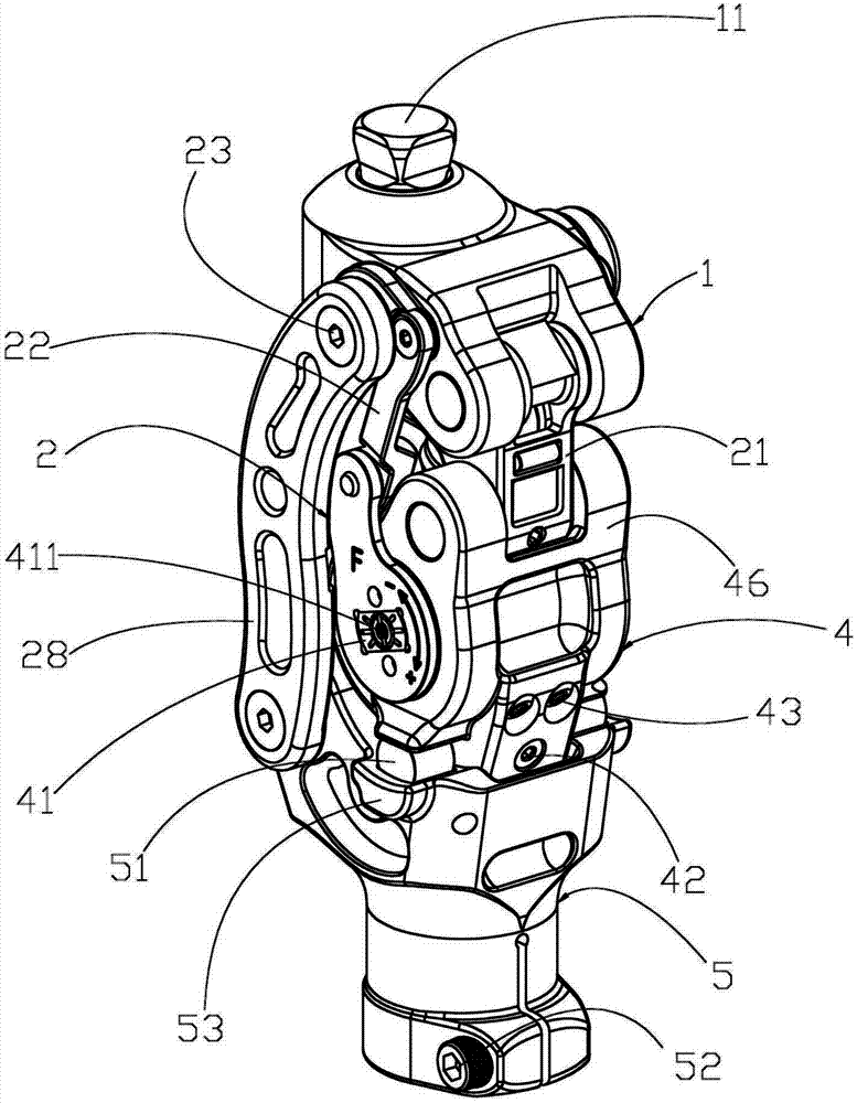
Fig. 1: be the axonometric chart of the present invention's four connecting rods buffering oil pressure knee joint structure.
Fig. 2: be the front view of the present invention's four connecting rods buffering oil pressure knee joint structure.
Fig. 3: be the right view of the present invention's four connecting rods buffering oil pressure knee joint structure.
Fig. 4: be the profile of the present invention's four connecting rods buffering oil pressure knee joint structure.
Fig. 5: be the profile of the present invention's four connecting rods buffering oil pressure knee joint structure.
Fig. 6: be the profile of the present invention's four connecting rods buffering oil pressure knee joint structure.
Fig. 7: be the three-dimensional system diagram of the present invention's four connecting rods buffering oil pressure knee joint structure.
Fig. 8: be the three-dimensional system diagram of the present invention's four connecting rods buffering oil pressure knee joint structure.
Fig. 9-1: be the profile of one embodiment of the invention buffer unit structure.
Fig. 9-2: be the profile of one embodiment of the invention buffer unit C-C line.
Fig. 9-3: be the profile of one embodiment of the invention buffer unit D-D line.
Figure 10-1: be the profile of one embodiment of the invention buffer unit structure.
Figure 10-2: be the profile of one embodiment of the invention buffer unit C-C line.
Figure 10-3: be the profile of one embodiment of the invention buffer unit D-D line.
Figure 11-1: be the profile of one embodiment of the invention buffer unit structure.
Figure 11-2: be the profile at another visual angle of one embodiment of the invention buffer unit structure.
Figure 12-1: be the profile of one embodiment of the invention buffer unit structure.
Figure 12-2: be the profile at another visual angle of one embodiment of the invention buffer unit structure.
Figure 13-1: be the profile of one embodiment of the invention four connecting rod oil pressure body structures.
Figure 13-2: be the sectional axonometric drawing of one embodiment of the invention four connecting rod oil pressure body structures.
Figure 14: be the action schematic diagram of one embodiment of the invention four connecting rod oil pressure body structures.
Figure 15: be the action profile of one embodiment of the invention four connecting rod oil pressure body structures.
Figure 16: be the action profile of one embodiment of the invention four connecting rod oil pressure body structures.
Figure 17: be the action profile of one embodiment of the invention four connecting rod oil pressure body structures.
Figure 18-1: be the part section enlarged drawing of one embodiment of the invention four connecting rod oil pressure body structures.
Figure 18-2: be the part section enlarged drawing of one embodiment of the invention four connecting rod oil pressure body structures.
Figure 19: be the user mode schematic diagram of the present invention's four connecting rods buffering oil pressure knee joint structure.
The primary clustering symbol description:
1 four connecting rod oil heads
11 adjustable screws
2 linkages
21 connecting rods
22 pull bars
23 interior hexagonal flat head screws
24 needle bearings
25 axle center
26 ball bearings
27 packing rings
28 arc sheets
3 elastic force apparatus
The 31 spring seats of honour
32 spring adjusting seats
33 springs
34 axle center
35 packing rings
4 buffer units
41 oil pressure axle center
411 adjusting knobs
42 loop screws
43 fixed screws
44 repairing pistons
45 adjust screw
46 4 connecting rod oil pressure bodies
47 non-return valves
48 link stoppers
481 cup head hexagon socket head cap screws
49 star-like rings
491 steel balls
5 buffer bodies
51 shock-proof blocks
52 hold the hole screw
The 53 buffering wings
The perforation of 54 protruding pinnas
6 Control Shafts
61 clasps
62 pads
63 balls
7 safety devices
8 unidirectional repairing controlling organizations
81 automatic makeup grease chambeies
9 asphalt channels
91 asphalt channel holes
10 Automatic Cycle oil sectors
The specific embodiment
Below with regard to structure function of the present invention, adopt by preferred embodiment, cooperate graphic detailed description after, making increases understanding of the present invention; The present invention is a kind of buffering oil pressure articulation structure, sees also shown in drawing among Fig. 1 ~ Figure 19, and primary structure comprises one or four connecting rod oil heads 1, a linkage 2, an elastic force apparatus 3, a buffer unit 4, a buffer body 5;
See also shown in drawing among Fig. 1 ~ Figure 19, this connecting rod 21 is through being sleeved on four connecting rod oil heads, 1 inner groovy, four connecting rod oil heads, 1 outside is counted the hole and is connected respectively arc sheet 28, pull bar 22, by needle bearing 24, the location is inserted in interior hexagonal flat head screw 23 and axle center 25,21 times square punch of connecting rod and four connecting rod oil heads, 1 groove fit, insert the location by needle bearing 24 and axle center 34,22 times square punch of pull bar are arranged at four connecting rod oil pressure bodies, 46 central hole places, screw togather with interior hexagonal flat head screw 23,46 times square punch of four connecting rod oil pressure bodies are through 5 perforation place of snapping buffer body, needle bearing 24 cooperates an axle center 34 to insert the location, the buffer body 5 perforation place outsides is equipped with arc sheet 28 and interlocks and establish, and is screwed togather by hexagonal flat head screw 23 in several; Connecting rod 21 inner groovies are joined on the elastic force apparatus 3 the square punch place and are joined axle center 34 and needle bearing 24 is inserted the location through ball bearing 26 and packing ring, four connecting rod oil pressure bodies, 46 protruding pinnas perforation 54 is then joined in elastic force apparatus 3 belows, by axle center 34, packing ring 35, ball bearing 26 location, four connecting rod oil pressure bodies, 46 below snapping shock-proof blocks 51 close in the buffering wing 53.
See also shown in drawing among Fig. 1 ~ Figure 19, the present invention's four connecting rods buffering oil pressure knee joint mainly utilizes oil pressure axle center 41 to change setting position, and utilize link stopper 48 and cup head hexagon socket head cap screw 481 and non-return valve 47 to form Automatic Cycle oil sector 10, when four connecting rods buffering oil pressure knee joint closes the knee joint running, the above-mentioned Automatic Cycle oil sector 10 of its oil pressure axle center 41 usefulness carries out oil pressure to be regulated, non-return valve 47 is as the usefulness of check valve, control crooked with extension direct current to conversion, non-return valve 47, spring 33, loop screw 42 forms unidirectional repairing controlling organization 8, case of bending when rotate in oil pressure axle center 41, thrust with oil pressure clogs the hole to non-return valve 47, pressure can't be entered in the automatic makeup grease chamber 81, work as straight configuration, then utilize automatic makeup grease chamber 81 interior set spring 33 pressure-driven repairing pistons 44 toward interior extruding, make the regular supply of the stable also energy of oil pressure.Automatic makeup grease chamber 81 interior lubricating oil can be with make-up oil after adjustment screw 45 dismountings of automatic makeup grease chamber 81 when service wear causes deficiency; 41 outsides, oil pressure axle center are then fixed with star-like ring 49, steel ball 491, packing ring 27, loop screw 42, fixed screw 43, can utilize adjusting knob 411 to carry out the speed adjustment, to have the buffer speed function of adjustable concurrently.
See also shown in drawing among Figure 13-1 ~ Figure 19, the present invention's four connecting rods buffering oil pressure knee joint arranges change because of buffer unit 4 inner four connecting rod oil pressure bodies 46, add a Control Shaft 6, its Control Shaft 6 sequentially passes a star-like ring 49, a pad 62, a clasp 61, a spring 33 by fixed screw 43 and is consisted of.When automatic makeup grease chamber 81 is subject to spring 33 pressure-driven repairing pistons 44 toward interior extruding, its asphalt channel 9 tail ends are kept the unimpeded and stable oil pressure of oil circuit because 63 several of balls are set, when walking states by standing, when tilting both mutual conversion, during standing state, safety device 7 interior Control Shafts 6 can't upwards hinder file oil by asphalt channel hole 91, when heeling condition, the Control Shaft 6 that just can drive this safety device 7 is boosted, stop asphalt channel hole 91 to asphalt channel 9 tops, reach blocking-up oil and lead to asphalt channel 9 purposes, to have its baffle safety braking function that can land safely concurrently; The above only is preferred embodiment of the present invention, when can not with as limiting scope of the invention process, all equalizations of doing according to the present patent application claim change or modify, and must belong in the scope that patent of the present invention contains.

Claims (6)

1.一种缓冲油压关节结构,包含;一四连杆油压头、一连动装置、一弹力装置、一缓冲装置、一缓冲体组件相组合轴心设置组成,四连杆油压头用于向上连接大腿处,下缘缓冲体为连接小腿处,其中:该连杆经套合于四连杆油压头内凹槽,四连杆油压头外侧数孔分别连接弧片、拉杆,由滚针轴承、内六角平头螺丝及轴心置入定位,连杆下方穿孔与四连杆油压头凹槽配合,由滚针轴承及轴心置入定位,拉杆下方穿孔设置于四连杆油压体中心穿孔处,以内六角平头螺丝螺合,四连杆油压体下方穿孔经扣接缓冲体穿孔处,滚针轴承配合一轴心置入定位,缓冲体穿孔处外侧配以弧片相扣设,由数个内六角平头螺丝螺合;连杆内凹槽配弹力装置上方穿孔处经滚珠轴承与垫圈配轴心及滚针轴承置入定位,弹力装置下方则配四连杆油压体凸耳部穿孔,由轴心、垫圈、滚珠轴承定位,四连杆油压体下方扣接防震块合于缓冲翼;1. A cushioning oil pressure joint structure, comprising: a four-bar linkage oil pressure head, a linkage device, an elastic device, a buffer device, and a buffer body assembly combined with an axis setting, and the four-bar linkage oil pressure head It is used to connect the thigh upwards, and the buffer body at the lower edge is used to connect the calf, wherein: the connecting rod is fitted into the inner groove of the four-link hydraulic head, and the holes on the outside of the four-link hydraulic head are respectively connected to the arc and the tie rod , the needle roller bearing, the inner hexagonal flat head screw and the shaft center are placed and positioned, the perforation under the connecting rod is matched with the groove of the four-link oil pressure head, the needle roller bearing and the shaft center are placed and positioned, and the hole under the tie rod is set in the four-connected The hole in the center of the hydraulic body of the rod is screwed with the hexagon socket head screw, the hole under the four-link hydraulic body is fastened to the hole of the buffer body, the needle bearing is positioned with an axis, and the outer side of the hole of the buffer body is equipped with an arc. The pieces are interlocked and screwed together by several hexagon socket flat head screws; the inner groove of the connecting rod is equipped with the upper hole of the elastic device, and the ball bearing, the washer, the shaft center and the needle bearing are placed in the position, and the bottom of the elastic device is equipped with four connecting rods. The lug of the oil pressure body is perforated, and is positioned by the shaft center, washer, and ball bearing, and the anti-vibration block is fastened under the four-link oil pressure body to fit the buffer wing; 其特征在于:油压轴心设置于四连杆油压体中心穿孔处,利用弹簧压力及补油活塞设置,可使内部油量不足时能够自行补充。It is characterized in that: the oil pressure axis is set at the perforation in the center of the four-link oil pressure body, and the spring pressure and the oil supply piston are used to make the internal oil supply self-replenish when it is insufficient. 2.根据权利要求1所述的缓冲油压关节结构,其特征在于:其油压轴心,可利用轴心两侧调节钮进行弯曲速度及反弹回复速度调整。2. The cushioning hydraulic joint structure according to claim 1, characterized in that: the hydraulic shaft center can be adjusted by adjusting the bending speed and rebound recovery speed by using the adjustment knobs on both sides of the shaft center. 3.根据权利要求1所述的缓冲油压关节结构,其特征在于:因油压设置改变,体积可缩减。3. The buffer oil pressure joint structure according to claim 1, characterized in that the volume can be reduced due to the change of the oil pressure setting. 4.根据权利要求1所述的缓冲油压关节结构,其特征在于:因缓冲装置内部四连杆油压体设置改变,加入一控制轴,其控制轴为固定螺丝依序穿过一星型环、一垫片、一扣环、一弹簧所构成。4. The buffer hydraulic joint structure according to claim 1, characterized in that: due to the change in the setting of the four-link hydraulic body inside the buffer device, a control shaft is added, and the control shaft is a fixed screw passing through a star-shaped joint in sequence. Ring, a gasket, a buckle, and a spring. 5.根据权利要求1所述的缓冲油压关节结构,其特征在于:因缓冲装置内部四连杆油压体设置改变,其控制轴当产生后倾下压,其控制轴往上推阻油路通道,产生着地缓冲安全煞车动作。5. The buffer hydraulic joint structure according to claim 1, characterized in that: due to the change in the setting of the four-link hydraulic body inside the buffer device, when the control shaft is tilted backward and pressed down, the control shaft pushes up to block the oil. The road channel produces a ground cushioning safety braking action. 6.根据权利要求1所述的缓冲油压关节结构,其特征在于:因缓冲装置内部四连杆油压体设置改变,其控制轴由固定螺丝调整高低。6. The buffer hydraulic joint structure according to claim 1, characterized in that: due to the change in the configuration of the four-link hydraulic body inside the buffer device, the height of the control shaft is adjusted by fixing screws.
CN201210324810.3A 2011-09-30 2012-09-04 Four-link buffer oil pressure knee joint Active CN103027770B (en)

Applications Claiming Priority (2)

Application Number Priority Date Filing Date Title
TW100135412 2011-09-30
TW100135412A TW201313213A (en) 2011-09-30 2011-09-30 Four-bar linkage cushion hydraulic knee joint

Publications (2)

Publication Number Publication Date
CN103027770A true CN103027770A (en) 2013-04-10
CN103027770B CN103027770B (en) 2015-03-25

Family

ID=47144399

Family Applications (1)

Application Number Title Priority Date Filing Date
CN201210324810.3A Active CN103027770B (en) 2011-09-30 2012-09-04 Four-link buffer oil pressure knee joint

Country Status (6)

Country Link
US (1) US9005309B2 (en)
CN (1) CN103027770B (en)
DE (1) DE102012109061B4 (en)
GB (1) GB2495189B (en)
TR (1) TR201211029A2 (en)
TW (1) TW201313213A (en)

Cited By (2)

* Cited by examiner, † Cited by third party
Publication number Priority date Publication date Assignee Title
CN107898537A (en) * 2017-11-09 2018-04-13 赵玉芯 A kind of joint prosthesis platform gasket assembly
CN120307267A (en) * 2025-06-16 2025-07-15 杭州智元研究院有限公司 Novel modularization knee joint helps capable system

Families Citing this family (8)

* Cited by examiner, † Cited by third party
Publication number Priority date Publication date Assignee Title
TWI477264B (en) * 2012-11-07 2015-03-21 Pro Limb Internat Corp Adjustable below-the-knee prosthetic leg
DE102014000020B4 (en) * 2014-01-03 2021-03-11 Ottobock Se & Co. Kgaa Prosthetic knee joint
TWM518073U (en) * 2015-12-10 2016-03-01 Pro Limb Internat Corp Prosthetic knee joint with damping and engagement effect
CN105662664B (en) * 2016-01-12 2017-08-08 丁科才 A kind of semi-automatic artificial thigh
CN107456299A (en) * 2016-06-02 2017-12-12 肯达路企业股份有限公司 Oil pressure ankle joint
DE102017126396B4 (en) * 2017-11-10 2020-02-06 Otto Bock Healthcare Products Gmbh Spring device and hydraulic actuator
TWI726599B (en) * 2020-02-03 2021-05-01 肯達路企業股份有限公司 Knee joint structure
US12427041B1 (en) * 2024-03-25 2025-09-30 Ken Dall Enterprise Co., Ltd. Knee joint structure featuring hydraulic control

Citations (7)

* Cited by examiner, † Cited by third party
Publication number Priority date Publication date Assignee Title
DE20306821U1 (en) * 2003-05-02 2003-06-18 Chen, Sen-Jung, Taipeh/T'ai-pei Prosthetic knee joint to replace normal knee action has double link action with third link compressing spring and hydraulic system as knee bends
TWM256156U (en) * 2004-02-16 2005-02-01 Ken Dall Entpr Co Ltd Improved structure for fixing and buffering the knee joint
TWM273328U (en) * 2004-12-31 2005-08-21 Ken Dall Entpr Co Ltd Improved buffer structure for knee joint
CN2815304Y (en) * 2005-01-24 2006-09-13 肯达路企业有限公司 A prosthetic knee joint with cushioning effect
CN201365988Y (en) * 2009-02-03 2009-12-23 肯达路企业有限公司 Knee joint buffer structure
CN201624815U (en) * 2010-04-08 2010-11-10 陈建文 Hydraulic shock absorber for knee joint and knee joint
CN202069722U (en) * 2011-04-27 2011-12-14 长宇机械实业有限公司 Artificial knee joint

Family Cites Families (6)

* Cited by examiner, † Cited by third party
Publication number Priority date Publication date Assignee Title
TWI276430B (en) * 2002-11-21 2007-03-21 Nabtesco Corp Prosthetic limb having knee braking function
US7044983B1 (en) 2003-07-24 2006-05-16 Chia Pao Cheng Positioning and buffering device for artificial knee joint
US20090143869A1 (en) * 2007-11-29 2009-06-04 Chia-Pao Cheng Anti-shock artificial knee joint structure
TWM362686U (en) * 2008-10-22 2009-08-11 Pro Limb Internat Corp Safety artificial limb joint without interference
TWM359316U (en) 2009-01-23 2009-06-21 Ken Dall Entpr Co Ltd Buffer structure for knee joint
TW201235022A (en) * 2011-02-16 2012-09-01 Ken Dall Entpr Co Ltd Four-linkage brake knee joint

Patent Citations (7)

* Cited by examiner, † Cited by third party
Publication number Priority date Publication date Assignee Title
DE20306821U1 (en) * 2003-05-02 2003-06-18 Chen, Sen-Jung, Taipeh/T'ai-pei Prosthetic knee joint to replace normal knee action has double link action with third link compressing spring and hydraulic system as knee bends
TWM256156U (en) * 2004-02-16 2005-02-01 Ken Dall Entpr Co Ltd Improved structure for fixing and buffering the knee joint
TWM273328U (en) * 2004-12-31 2005-08-21 Ken Dall Entpr Co Ltd Improved buffer structure for knee joint
CN2815304Y (en) * 2005-01-24 2006-09-13 肯达路企业有限公司 A prosthetic knee joint with cushioning effect
CN201365988Y (en) * 2009-02-03 2009-12-23 肯达路企业有限公司 Knee joint buffer structure
CN201624815U (en) * 2010-04-08 2010-11-10 陈建文 Hydraulic shock absorber for knee joint and knee joint
CN202069722U (en) * 2011-04-27 2011-12-14 长宇机械实业有限公司 Artificial knee joint

Cited By (2)

* Cited by examiner, † Cited by third party
Publication number Priority date Publication date Assignee Title
CN107898537A (en) * 2017-11-09 2018-04-13 赵玉芯 A kind of joint prosthesis platform gasket assembly
CN120307267A (en) * 2025-06-16 2025-07-15 杭州智元研究院有限公司 Novel modularization knee joint helps capable system

Also Published As

Publication number Publication date
DE102012109061B4 (en) 2018-05-30
DE102012109061A1 (en) 2013-04-04
GB2495189B (en) 2013-10-23
GB2495189A (en) 2013-04-03
CN103027770B (en) 2015-03-25
TW201313213A (en) 2013-04-01
TWI450711B (en) 2014-09-01
US20130085580A1 (en) 2013-04-04
TR201211029A2 (en) 2013-08-22
US9005309B2 (en) 2015-04-14
GB201216586D0 (en) 2012-10-31

Similar Documents

Publication Publication Date Title
CN103027770A (en) Four-link buffer oil pressure knee joint
EP3212040B1 (en) Office, work and leisure chair and retrofit kit for a chair or a seat surface for causing subliminal movements of the person sitting thereon
CN104473486B (en) A kind of adjustable for height wearable seat
TWI533815B (en) Manual and automatic pressure control of the shoe cushion
CN205512623U (en) Comfortable adjustable sports shoes
KR100968038B1 (en) The apparatus for height-adjusting of pressure fluctuation type
CN105105410B (en) Height-adjustable leisure shoe
CN201775750U (en) Massage mechanism simulating zero-gravity state
DE202007000676U1 (en) Office chair has wheeled base, on which support column is mounted, which is made up of rigid lower plate, to which wheels are attached, and upper plate carrying column with springs between two plates
CN119280761A (en) Anti-fall treadmill with buffer shock absorption structure
CN104787156B (en) Simulate bicycle saddle structure capable of swinging leftward and rightward
CN202665757U (en) Knee joint artificial limb
CN201564752U (en) Lifting device of massage movement for massaging buttocks
CN201046318Y (en) Jumping shoes with adjustable resilience
CN216601836U (en) Sole cushioning protection structure and impact-resistant running shoes
CN206043894U (en) A kind of chair for student
CN201192548Y (en) Ascending device
CN208625035U (en) A kind of intelligent electric mattress balanced structure
CN202588525U (en) Shoe pad with breathable structure
CN202619119U (en) Cervical vertebra therapy and rehabilitation healthcare pillow
CN103169299B (en) Ventilative scattered pressure pad
CN201263522Y (en) Chair back support structure with adjustable waist cushion
CN114715311B (en) T-shaped inclined plane concave type bicycle saddle
CN201624815U (en) Hydraulic shock absorber for knee joint and knee joint
CN205682591U (en) A kind of ventilative lightweight running shoes sole

Legal Events

Date Code Title Description
C06 Publication
PB01 Publication
C10 Entry into substantive examination
SE01 Entry into force of request for substantive examination
C14 Grant of patent or utility model
GR01 Patent grant