CN103114902A - Motor cooling water pump assembly and flow-quantity controlling method thereof - Google Patents
Motor cooling water pump assembly and flow-quantity controlling method thereof Download PDFInfo
- Publication number
- CN103114902A CN103114902A CN2012104269836A CN201210426983A CN103114902A CN 103114902 A CN103114902 A CN 103114902A CN 2012104269836 A CN2012104269836 A CN 2012104269836A CN 201210426983 A CN201210426983 A CN 201210426983A CN 103114902 A CN103114902 A CN 103114902A
- Authority
- CN
- China
- Prior art keywords
- water inlet
- engine
- water
- inlet valve
- valve core
- Prior art date
- Legal status (The legal status is an assumption and is not a legal conclusion. Google has not performed a legal analysis and makes no representation as to the accuracy of the status listed.)
- Granted
Links
Images


Landscapes
- Structures Of Non-Positive Displacement Pumps (AREA)
Abstract
本发明公开了一种发动机冷却水泵总成及其流量控制方法,该水泵总成在水泵壳体上设有第一、第二旋转阀门,发动机ECU则根据环境温度、发动机工况通过步进电机控制第一、第二旋转阀门的开度,从而实现对发动机温度的快速调整,ECU同时记录流量调整到位时步进电机的转动角度值,并将其替换储存在ECU中相应的控制数据,使控制数据得以实时更新。本发明发动机暖机时间更短,并可避免发动机在部分负荷时的过度冷却,发动机的温度控制快速准确,从而使发动机的燃烧更加充分,并降低发动机的排放,提高发动机的经济性能。
The invention discloses an engine cooling water pump assembly and a flow control method thereof. The water pump assembly is provided with first and second rotary valves on the water pump housing, and the engine ECU passes the stepping motor according to the ambient temperature and engine working conditions. Control the opening of the first and second rotary valves to achieve rapid adjustment of the engine temperature. The ECU simultaneously records the rotation angle value of the stepping motor when the flow is adjusted in place, and replaces it with the corresponding control data stored in the ECU. Control data is updated in real time. The engine warm-up time of the invention is shorter, and excessive cooling of the engine at partial load can be avoided, and the temperature control of the engine is fast and accurate, so that the combustion of the engine is more sufficient, the emission of the engine is reduced, and the economic performance of the engine is improved.
Description
技术领域 technical field
本发明涉及一种汽车的发动机冷却水泵,具体涉及一种可根据发动机工况自动调节发动机冷却水流量以控制冷却水温度的水泵总成、以及相应的流量控制方法。 The invention relates to an engine cooling water pump of an automobile, in particular to a water pump assembly which can automatically adjust the flow of engine cooling water according to the working conditions of the engine to control the temperature of the cooling water, and a corresponding flow control method. the
背景技术 Background technique
汽车发动机有一个最佳的工作温度,在该温度下,各运行部件之间的配合间隙等处于最佳状态,此时发动机的工作效率高,燃烧更加充分,并可最大限度地减少发动机的排放。目前,汽车发动机的温度控制通常是由一种具有主、副阀门的蜡式调温器实现的,调温器同时控制主阀门和副阀门的开闭,主阀门用于控制冷却水大循环通道,而副阀门则用于控制冷却水小循环通道。当发动机启动时,发动机冷却水的温度较低,此时调温器的主阀门处于关闭状态,而副阀门则处于开启状态,发动机冷却水走小循环,冷却水不通过散热器冷却,因而不对发动机进行冷却,发动机的温度可以较快地上升以实现发动机的暖机,进而使发动机能进入正常的工作状态。当发动机正常工作时,发动机冷却水温度升高,调温器内的石蜡在感应体内熔化膨胀,进而推动其内的推杆轴向移动,在推杆移动的同时带动调温器主阀门打开,并相应地关闭副阀门,此时发动机冷却水走大循环,对发动机进行冷却,从而使发动机温度降低,以确保其工作在合理的温度范围。 Automobile engines have an optimal working temperature, at which temperature, the fit gap between various running parts is in the best state, at this time, the engine has high working efficiency, more complete combustion, and can minimize engine emissions . At present, the temperature control of automobile engines is usually realized by a wax-type thermostat with main and auxiliary valves. The thermostat controls the opening and closing of the main valve and the auxiliary valve at the same time. The main valve is used to control the large circulation channel of cooling water , while the auxiliary valve is used to control the small cooling water circulation channel. When the engine is started, the temperature of the engine cooling water is low. At this time, the main valve of the thermostat is closed, while the auxiliary valve is open. The engine cooling water goes through a small cycle, and the cooling water does not pass through the radiator. The engine is cooled, and the temperature of the engine can rise quickly to warm up the engine, so that the engine can enter a normal working state. When the engine is working normally, the temperature of the engine cooling water rises, and the paraffin wax in the thermostat melts and expands in the induction body, and then pushes the push rod in it to move axially. When the push rod moves, it drives the main valve of the thermostat to open. And correspondingly close the auxiliary valve. At this time, the engine cooling water goes through a large circulation to cool the engine, thereby reducing the engine temperature to ensure that it works within a reasonable temperature range.
例如,在中国专利文献上公开的“一种调温器”,其申请公布号为CN102588067A,它包括盖、支架、顶出机构及固定在顶出机构上与其联动的主阀门、副阀门和密封件,顶出机构由推杆、主弹簧、柱状蜡式感应体组成,柱状蜡式感应体设有感应体底座,感应体上盖,感应体底座和感应体上盖之间设有蜡室,推杆和蜡室之间设有橡胶膜片;所述感应体上盖、推杆和橡胶膜片之间设有橡胶密封圈。该调温器采用感温蜡做动力源,利用蜡的热膨胀力引起密封橡胶膜片的轴向变形,从而推动阀门做开启、闭合动作。 For example, "a kind of thermostat" disclosed in the Chinese patent literature has an application publication number of CN102588067A, which includes a cover, a bracket, an ejection mechanism, and a main valve fixed on the ejection mechanism, an auxiliary valve and a sealing valve linked with it. The ejection mechanism is composed of a push rod, a main spring, and a columnar wax-type induction body. The columnar wax-type induction body is provided with an induction body base, an induction body upper cover, and a wax chamber is provided between the induction body base and the induction body upper cover. A rubber diaphragm is arranged between the push rod and the wax chamber; a rubber sealing ring is arranged between the upper cover of the induction body, the push rod and the rubber diaphragm. The thermostat uses temperature-sensitive wax as the power source, and uses the thermal expansion force of the wax to cause the axial deformation of the sealing rubber diaphragm, thereby pushing the valve to open and close.
然而,通过蜡式调温器控制发动机温度存在以下问题:由于是通过控制发动机冷却水的温度来间接地控制发动机的温度,因此不能根据发动机实际的工况来调节调温器阀门的开度,不能实现精确控制发动机的温度。汽车发动机冷却水泵是按照最大热负荷时所需要的冷却性能设计的,因此当发动机在低转速、低负荷运转状态时,发动机被过度冷却,并且蜡式调温器的反应速度慢,从而使发动机水温波动大,不利于发动机油耗及排放的降低。 However, there are following problems in controlling the engine temperature through the wax-type thermostat: since the temperature of the engine is indirectly controlled by controlling the temperature of the engine cooling water, the opening of the thermostat valve cannot be adjusted according to the actual working conditions of the engine. Precise control of the temperature of the engine cannot be achieved. The cooling water pump of automobile engine is designed according to the cooling performance required by the maximum heat load, so when the engine is running at low speed and low load, the engine is overcooled, and the response speed of the wax-type thermostat is slow, so that the engine Large fluctuations in water temperature are not conducive to the reduction of engine fuel consumption and emissions.
the
发明内容 Contents of the invention
本发明的目的是为了解决现有技术所存在的不能根据发动机实际工况来精确控制发动机的温度、以及发动机水温波动大的问题,提供一种可根据发动机实际工况快速、精确地控制发动机的发动机冷却水泵总成以及相应的流量控制方法,从而使发动机热机时能够快速暖机,并改善发动机在部分负荷时的冷却效果,以使发动机的燃烧更加充分,降低发动机的排放,提高发动机的经济性能。 The purpose of the present invention is to solve the problems in the prior art that the temperature of the engine cannot be accurately controlled according to the actual working conditions of the engine and the large fluctuation of the engine water temperature, and to provide a system that can quickly and accurately control the engine according to the actual working conditions of the engine. The engine cooling water pump assembly and the corresponding flow control method, so that the engine can be warmed up quickly when the engine is hot, and the cooling effect of the engine at part load can be improved, so that the combustion of the engine can be more complete, the emission of the engine can be reduced, and the economy of the engine can be improved. performance.
为了实现上述目的,本发明采用以下技术方案: In order to achieve the above object, the present invention adopts the following technical solutions:
一种发动机冷却水泵总成,包括水泵壳体,水泵壳体一端设置有叶轮腔,叶轮腔内设有叶轮轴,叶轮轴上固定有叶轮,叶轮轴伸出叶轮腔外的一端固定有驱动轮,所述叶轮腔在径向的侧壁上设有水泵出水口,水泵出水口内设有可转动的出水阀芯,从而构成第一旋转阀门,所述水泵壳体还设有与叶轮腔呈轴向排列圆柱形的进水阀腔,进水阀腔的侧壁上设有第一进水口,进水阀腔内设有可转动的进水阀芯,进水阀腔与进水阀芯构成第二旋转阀门,所述进水阀芯内设有沿进水阀腔的轴向延伸并与叶轮腔连通的进水通道,进水阀芯在轴向上对应第一进水口位置设有与进水通道相通的第一进水孔;水泵壳体内还设有控制电机,控制电机通过传动系统分别与进水阀芯以及出水阀芯相关联。 An engine cooling water pump assembly, including a water pump housing, an impeller chamber is arranged at one end of the water pump housing, an impeller shaft is arranged in the impeller chamber, an impeller is fixed on the impeller shaft, and a driving wheel is fixed at one end of the impeller shaft extending out of the impeller chamber , the impeller chamber is provided with a water pump outlet on the radial side wall, and a rotatable outlet valve core is arranged in the water outlet of the water pump, thus forming a first rotary valve. Axially arranged cylindrical water inlet valve chambers, a first water inlet is provided on the side wall of the water inlet valve chamber, a rotatable water inlet valve core is arranged in the water inlet valve chamber, and the water inlet valve chamber and the water inlet valve core Constitute the second rotary valve, the water inlet valve core is provided with a water inlet channel extending along the axial direction of the water inlet valve chamber and communicating with the impeller chamber, and the water inlet valve core is provided with a water inlet corresponding to the position of the first water inlet in the axial direction The first water inlet hole communicated with the water inlet channel; the water pump casing is also provided with a control motor, and the control motor is respectively associated with the water inlet valve core and the water outlet valve core through the transmission system.
本发明在用于发动机温度控制时,可省去现有的石蜡式调温器,水泵出水口和发动机水套的进水口相连接,第一进水口则和散热器的出水口相连接,这样,水泵总成上的第一旋转阀门可用于控制水泵输出到发动机水套的出水,而第二旋转阀门则用于控制经过散热器冷却的冷却水进入水泵。本发明不再单独根据冷却水温度控制发动机温度,而是由发动机的ECU根据发动机实际运转工况(转速、负载等)、发动机冷却水温度、环境温度等条件对控制电机进行快速控制,进而控制两个旋转阀门的开闭,以使发动机工作在最佳温度。与现有的石蜡式调温器相比较,其温度调控的速度更快捷,特别是可根据发动机的实际运行工况进行调控,避免当发动机在低转速、低负荷运转状态时被过度冷却,从而使发动机的燃烧更加充分,有利于降低发动机的排放,提高发动机的经济性能。当发动机刚启动时,第一、第二旋转阀门全部处于关闭状态,此时发动机内部的冷却水是完全封闭、不流动的,冷却水在水泵中进行自循环,因此整个发动机可更快速地实现暖机。 When the present invention is used for engine temperature control, the existing paraffin type thermostat can be omitted, the water pump outlet is connected with the water inlet of the engine water jacket, and the first water inlet is connected with the water outlet of the radiator, thus , the first rotary valve on the water pump assembly can be used to control the water output from the water pump to the engine water jacket, while the second rotary valve is used to control the cooling water cooled by the radiator into the water pump. In the present invention, the engine temperature is no longer controlled solely according to the cooling water temperature, but the ECU of the engine performs rapid control on the control motor according to the actual operating conditions of the engine (speed, load, etc.), engine cooling water temperature, ambient temperature, etc., and then controls The opening and closing of two rotary valves makes the engine work at the optimum temperature. Compared with the existing paraffin-type thermostat, the speed of temperature regulation is faster, especially it can be regulated according to the actual operating conditions of the engine, so as to avoid excessive cooling of the engine when the engine is running at low speed and low load, thereby The combustion of the engine is more complete, which is beneficial to reduce the emission of the engine and improve the economic performance of the engine. When the engine is just started, the first and second rotary valves are all closed. At this time, the cooling water inside the engine is completely closed and does not flow. The cooling water circulates in the water pump, so the whole engine can realize warm up.
作为优选,所述进水阀腔的侧壁上还设有第二进水口,进水阀芯上对应第二进水口位置设有与进水通道相通的第二进水孔。第二进水口用于和机油冷却器的出水口相连接,从而使进水阀芯和进水阀腔构成的第二旋转阀门可同时控制两条通道,当控制电机控制进水阀芯转动以调节发动机的冷却水流量时,可同时调控通过机油冷却器的冷却水流量,以控制机油冷却器的散热。 Preferably, a second water inlet is provided on the side wall of the water inlet valve cavity, and a second water inlet hole communicating with the water inlet channel is provided on the water inlet valve core corresponding to the second water inlet. The second water inlet is used to connect with the water outlet of the oil cooler, so that the second rotary valve formed by the water inlet spool and the water inlet valve cavity can control two channels at the same time, when the control motor controls the rotation of the water inlet spool to When adjusting the cooling water flow of the engine, the cooling water flow through the oil cooler can be adjusted at the same time to control the heat dissipation of the oil cooler.
作为优选,所述进水阀芯的外侧壁在轴向上对应第一、第二进水孔处分别具有弧形凸肩,进水阀腔则在第一、第二进水口处分别具有与弧形凸肩适配的弧形凹陷。在进水阀芯上设置两个弧形凸肩,弧形凸肩在纵向截面上呈外凸的弧形,从而使整个进水阀芯呈葫芦形,这样,内部设有进水通道的进水阀芯在第一、第二进水口处具有更高的抗压强度,从而有利于提高进水阀芯和进水阀腔之间的密封性能,并可降低进水阀芯的壁厚,有利于减轻重量和加工制造。此外,整体呈葫芦形的进水阀芯可极大地减少与进水阀腔的接触面积,从而可降低进水阀芯转动时的摩擦阻力,进而有利于控制电机对进水阀芯的控制。 As a preference, the outer wall of the water inlet valve core has arc-shaped shoulders corresponding to the first and second water inlets in the axial direction, and the water inlet valve chamber has arc-shaped shoulders at the first and second water inlets respectively. Curved recesses for matching shoulders. Two arc-shaped shoulders are arranged on the water inlet valve core, and the arc-shaped shoulders are convex arcs on the longitudinal section, so that the entire water inlet valve core is gourd-shaped. In this way, the inlet of the water inlet channel is provided inside. The water valve core has higher compressive strength at the first and second water inlets, which is conducive to improving the sealing performance between the water inlet valve core and the water inlet valve cavity, and can reduce the wall thickness of the water inlet valve core. Conducive to weight reduction and processing and manufacturing. In addition, the overall gourd-shaped water inlet spool can greatly reduce the contact area with the water inlet valve cavity, thereby reducing the frictional resistance when the water inlet spool rotates, which in turn facilitates the control of the motor on the water inlet spool.
作为优选,所述进水阀芯的进水通道内设有阀杆支承座,阀杆支承座的中心设置具有花键槽的支承孔;一进水阀杆插接在支承孔内,进水阀杆上设有与支承孔的花键槽适配的花键,进水阀杆远离叶轮腔一端连接有涡轮,控制电机的转轴上设置与涡轮啮合的蜗杆;进水阀芯在靠近叶轮腔一端设有主动齿轮,出水阀芯的阀杆上设有与主动齿轮啮合的从动齿轮。 As a preference, the water inlet channel of the water inlet valve core is provided with a valve stem support seat, and the center of the valve stem support seat is provided with a support hole with a spline groove; a water inlet valve stem is inserted into the support hole, and the water inlet valve The rod is provided with a spline adapted to the spline groove of the supporting hole. The end of the water inlet valve rod away from the impeller chamber is connected to a turbine, and the rotating shaft of the control motor is provided with a worm meshing with the turbine; the inlet valve core is provided at the end close to the impeller chamber. There is a driving gear, and the valve stem of the water outlet valve core is provided with a driven gear meshed with the driving gear.
本发明通过蜗轮蜗杆使控制电机驱动进水阀芯转动,同时进水阀芯通过主动齿轮和从动齿轮同步控制第一旋转阀门的开闭,从而方便第一、第二旋转阀门之间开闭时间的配合。由于进水阀芯同时起到传动轴的作用,因而有利于简化整个传动系统的结构,并且蜗轮蜗杆具有较大的传动比,可极大地缩小控制电机在转动时的误差对进水阀芯转动角度的影响,有利于提高两个旋转阀门的控制精度,并降低对控制电机的精度要求。 The invention uses the worm gear to drive the control motor to drive the water inlet valve core to rotate, and at the same time, the water inlet valve core synchronously controls the opening and closing of the first rotary valve through the driving gear and the driven gear, thereby facilitating the opening and closing of the first and second rotary valves time fit. Since the water inlet spool acts as a transmission shaft at the same time, it is beneficial to simplify the structure of the entire transmission system, and the worm gear has a large transmission ratio, which can greatly reduce the error of controlling the rotation of the motor to the rotation of the water inlet spool. The influence of the angle is beneficial to improve the control accuracy of the two rotary valves and reduce the accuracy requirements for the control motor.
作为优选,所述叶轮腔在径向的侧壁上还设有回水管,进水阀芯在设有第一进水孔的弧形凸肩处还设有回水孔,进水阀腔的侧壁上则对应地设有回水口,所述回水管与回水口连通。回水管、回水口、回水孔构成一个水泵的自循环通道,从而使进水阀芯和进水阀腔构成的第一旋转阀门可同时控制三条通道。发动机正常工作时,第一、第二旋转阀门开启,而自循环通道被切断,冷却水走大循环;在发动机启动暖机时,第一、第二旋转阀门同时关闭,自循环通道开启,水泵里面的冷却水可通过自循环通道自循环,因而有利于降低水泵自循环时的负载。 As a preference, the impeller cavity is also provided with a water return pipe on the radial side wall, and the water inlet valve core is also provided with a water return hole at the arc-shaped shoulder where the first water inlet hole is provided. A water return port is correspondingly provided on the side wall, and the water return pipe communicates with the water return port. The water return pipe, the water return port and the water return hole form a self-circulation channel of the water pump, so that the first rotary valve formed by the water inlet valve core and the water inlet valve cavity can control three channels at the same time. When the engine is working normally, the first and second rotary valves are opened, and the self-circulation channel is cut off, and the cooling water goes through a large circulation; when the engine starts to warm up, the first and second rotary valves are closed simultaneously, the self-circulation channel is opened, and the water pump The cooling water inside can be self-circulating through the self-circulation channel, thus helping to reduce the load of the water pump during self-circulation.
作为优选,所述第一进水孔为横向布置的等腰三角形。这样在进水阀芯增加一个相同的转动角度时,相应的进水截面积增加值会线性地变大,因而当发动机的温度刚刚超过最佳温度值时,冷却水的流量增加值较小,如果发动机的温度超过最佳温度值较多时,进水阀芯增加一个相同的转动角度而冷却水的流量增加值较大,因而既有利于发动机温度较高时的快速降温,又有利于发动机温度的精确控制。 Preferably, the first water inlet holes are laterally arranged isosceles triangles. In this way, when the water inlet spool increases the same rotation angle, the corresponding water inlet cross-sectional area increases linearly, so when the engine temperature just exceeds the optimum temperature value, the cooling water flow increase value is small, If the temperature of the engine exceeds the optimal temperature value by a large amount, the water inlet valve core will increase by the same rotation angle and the flow rate of cooling water will increase greatly. precise control.
一种基于权利要求1的发动机冷却水泵总成流量控制方法,包括如下步骤: A flow control method for an engine cooling water pump assembly based on claim 1, comprising the following steps:
a. 设定发动机温度变化的最小单位值以及出水阀芯和进水阀芯转动时的最小转动角度,发动机的ECU按事先设定的间隔时间重复采集发动机温度数据,并与预先设定的发动机工作温度最佳值进行比较; a. Set the minimum unit value of the engine temperature change and the minimum rotation angle when the water outlet valve core and the water inlet valve core rotate. Compare with the optimum value of working temperature;
b. 发动机在刚启动时,发动机温度低于发动机工作温度最佳值,ECU控制第一、第二旋转阀门关闭,水泵进行自循环,以实现发动机快速暖机: b. When the engine is just started, the engine temperature is lower than the optimal value of the engine operating temperature, the ECU controls the first and second rotary valves to close, and the water pump performs self-circulation to achieve rapid engine warm-up:
c. 当发动机温度上升至超过预先设定的工作温度最佳值至少一个最小单位值时,ECU根据环境温度、发动机运行工况以及预先存储的控制数据向控制电机发出相应指令使其转动一个角度,并通过传动系统使出水阀芯和进水阀芯正向地转动一个相应的角度,此时第一、第二旋转阀门打开一个对应的开口,对应流量的冷却水开始循环工作带走多余的热量; c. When the engine temperature rises to at least one minimum unit value exceeding the preset optimal operating temperature, the ECU sends a corresponding command to the control motor to rotate an angle according to the ambient temperature, engine operating conditions and pre-stored control data , and through the transmission system, the water outlet valve core and the water inlet valve core are rotated at a corresponding angle in a positive direction. At this time, the first and second rotary valves open a corresponding opening, and the cooling water corresponding to the flow rate starts to circulate to take away the excess heat;
d. 当发动机的ECU再次采集到的发动机温度数据与最佳值之间的差值的绝对值小于一个最小单位值时,ECU控制第一、第二旋转阀门的开度保持不变,如果发动机温度数据与最佳值之间的差值为正值且绝对值大于一个最小单位值时,则ECU控制控制电机转动使出水阀芯和进水阀芯正向地转动一个最小转动角度,如果发动机温度数据与最佳值之间的差值为负值且绝对值大于一个最小单位值时,则ECU控制控制电机转动使出水阀芯和进水阀芯反向地转动一个最小转动角度,以此类推,直至发动机温度数据与最佳值之间的差值的绝对值小于一个最小单位值为止。 d. When the absolute value of the difference between the engine temperature data collected by the engine ECU and the optimum value is less than a minimum unit value, the ECU controls the opening of the first and second rotary valves to remain unchanged. If the engine When the difference between the temperature data and the optimal value is a positive value and the absolute value is greater than a minimum unit value, the ECU controls the motor to rotate so that the water outlet valve core and the water inlet valve core rotate positively for a minimum rotation angle, if the engine When the difference between the temperature data and the optimal value is a negative value and the absolute value is greater than a minimum unit value, the ECU controls the motor to rotate so that the water outlet spool and the water inlet spool reversely rotate a minimum rotation angle, so that By analogy, until the absolute value of the difference between the engine temperature data and the optimal value is less than a minimum unit value.
本发明的流量控制方法中摒弃了现有技术通过石蜡式调温器的控制方式,改为电子控制,ECU预先存储的控制数据包括环境温度、发动机运行工况以及对应的控制电机转动角度,当发动机的温度超过最佳值时,ECU即可根据控制数据快速地控制第一、第二旋转阀门的开度,从而使发动机的温度能快速地得以调整,使发动技能保持在最佳工作状态。特别是,当ECU根据控制数据控制第一、第二旋转阀门的开度后,还可继续采集发动机的温度数据信息,并相应地使出水阀芯和进水阀芯转动一个最小转动角度,以便对发动机的温度进行微调,使其保持在最佳工作温度。 In the flow control method of the present invention, the control mode of the prior art through the paraffin-type thermostat is replaced by electronic control, and the control data stored in advance by the ECU includes the ambient temperature, the operating conditions of the engine and the corresponding control motor rotation angle. When the temperature of the engine exceeds the optimal value, the ECU can quickly control the opening of the first and second rotary valves according to the control data, so that the temperature of the engine can be adjusted quickly, and the starting function can be kept in the best working state. In particular, after the ECU controls the opening degrees of the first and second rotary valves according to the control data, it can continue to collect the temperature data information of the engine, and correspondingly make the water outlet valve core and the water inlet valve core rotate a minimum rotation angle, so that Make fine adjustments to the temperature of the engine to keep it at the optimum operating temperature.
作为优选,在步骤d中,当ECU采集到的发动机温度数据与最佳值之间的差值的绝对值小于一个最小单位值时,记录此时的控制电机总转动角度值,并将其替换预先存储的控制数据中对应此时环境温度、发动机运行工况的控制电机转动角度值。 Preferably, in step d, when the absolute value of the difference between the engine temperature data collected by the ECU and the optimum value is less than a minimum unit value, record the total rotation angle value of the control motor at this time, and replace it In the pre-stored control data, the rotation angle value of the control motor corresponds to the ambient temperature and the operating condition of the engine at this time.
由于ECU中预先存储的控制数据在控制发动机的温度时难免会有误差,因而本发明将汽车实际行驶时的控制数据存入ECU,并替换原有的控制数据,从而使控制数据更加符合汽车的实际运行情况,特别是,随着车辆行驶里程的增加,发动机的散热器性能等会有所变化,而本发明的上述控制数据是实时更新的,因而使冷却水的流量调整过程更快捷,确保发动机始终工作在最佳温度范围。 Since the pre-stored control data in the ECU will inevitably have errors when controlling the temperature of the engine, the present invention stores the control data when the car is actually running in the ECU and replaces the original control data, so that the control data is more in line with the temperature of the car. Actual operating conditions, especially, with the increase of vehicle mileage, the radiator performance of the engine, etc. will change, but the above-mentioned control data of the present invention is updated in real time, thereby making the flow adjustment process of cooling water faster and ensuring The engine always works in the optimum temperature range.
综上所述,本发明具有如下有益效果:发动机暖机时间更短,避免发动机在部分负荷时的过度冷却,发动机的温度控制快速准确,从而使发动机的燃烧更加充分,并降低发动机的排放,提高发动机的经济性能。 In summary, the present invention has the following beneficial effects: engine warm-up time is shorter, excessive cooling of the engine at partial load is avoided, the temperature control of the engine is fast and accurate, so that the combustion of the engine is more complete, and the emission of the engine is reduced. Improve the economic performance of the engine.
the
附图说明 Description of drawings
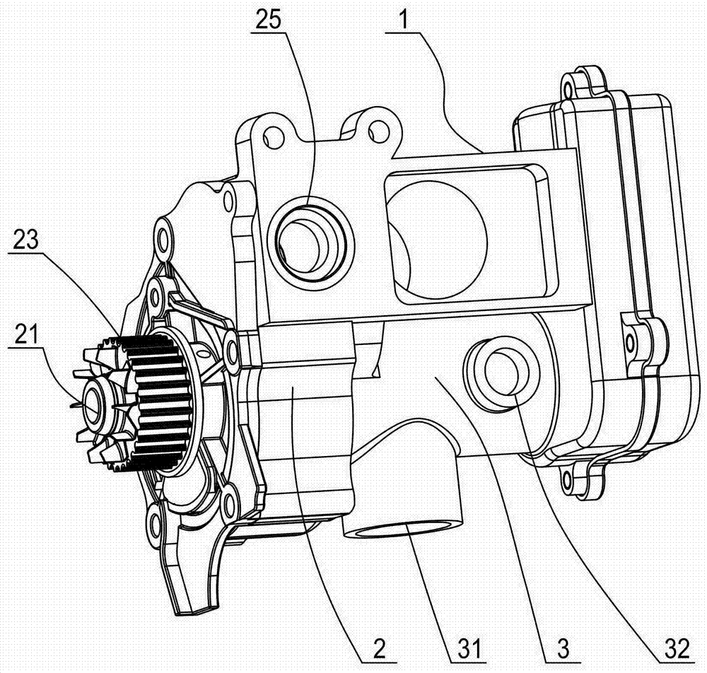
图1是本发明发动机冷却水泵总成的一种结构示意图。 Fig. 1 is a schematic structural view of the engine cooling water pump assembly of the present invention.
图2是本发明发动机冷却水泵总成去除水泵壳体后的结构示意图。 Fig. 2 is a schematic structural view of the engine cooling water pump assembly of the present invention after removing the water pump housing.
图中:1、水泵壳体 2、叶轮腔 21、叶轮轴 22、叶轮 23、驱动轮 24、出水阀芯 25、水泵出水口 3、进水阀腔 31、第一进水口 32、第二进水口 4、进水阀芯 41、弧形凸肩 42、第一进水孔 43、第二进水孔 44、回水孔 5、控制电机 61、涡轮 62、蜗杆 63、主动齿轮 64、从动齿轮 65、惰轮
In the figure: 1.
具体实施方式 Detailed ways
下面结合附图与具体实施方式对本发明做进一步的描述。 The present invention will be further described below in conjunction with the accompanying drawings and specific embodiments.
本发明的发动机冷却水泵总成流量控制方法所采用的是如图1、图2所示的发动机冷却水泵总成,该发动机冷却水泵总成包括水泵壳体1,水泵壳体内并排设置有叶轮腔2以及圆柱形的进水阀腔3,设置在水泵壳体一端的叶轮腔内设有叶轮轴21,叶轮轴上固定有叶轮22,叶轮轴一端伸出到叶轮腔外并在伸出端固定有驱动轮23,该驱动轮主要由发动机驱动,也可通过电机驱动,叶轮腔在径向的侧壁上设置水泵出水口25,水泵出水口内设置可转动的出水阀芯24,出水阀芯呈球形,其上设置相应的通孔,从而构成第一旋转阀门。
The engine cooling water pump assembly flow control method of the present invention adopts the engine cooling water pump assembly shown in Figure 1 and Figure 2, the engine cooling water pump assembly includes a water pump housing 1, and the impeller chambers are arranged side by side in the
进水阀腔沿叶轮腔的轴向排列,并与叶轮腔同轴布置,进水阀腔的侧壁上沿轴向错位设置有第一进水口31、第二进水口32,进水阀腔内则相应地设置可转动的进水阀芯4,进水阀腔与进水阀芯构成第二旋转阀门。进水阀芯总体为一薄壳类构件,其内部为沿进水阀腔的轴向延伸并与叶轮腔连通的进水通道,进水阀芯在轴向上对应第一、第二进水口位置分别设置与进水通道相通的第一进水孔42和第二进水孔43,第一、第二进水孔均为横向布置的等腰三角形。
The water inlet valve cavity is arranged along the axial direction of the impeller cavity, and is arranged coaxially with the impeller cavity. On the side wall of the water inlet valve cavity, a
为了提高进水阀芯的抗压强度,以增强其密封性能,进水阀芯的外侧壁在轴向上对应第一、第二进水孔处分别具有弧形凸肩41,从而使进水阀芯整体呈葫芦形,相应地,进水阀腔则在第一、第二进水口处分别具有与弧形凸肩适配的弧形凹陷。当然,为便于加工制造,第一、第二进水口处可以设置橡胶接头,该橡胶接头上设置进水的通孔,而靠内侧一端设置弧形凹陷并与进水阀芯的弧形凸肩贴合。
In order to increase the compressive strength of the water inlet valve core and enhance its sealing performance, the outer wall of the water inlet valve core has arc-shaped
叶轮腔在径向的侧壁上还设置有回水管(图中未示出),进水阀芯则在设置第一进水孔的弧形凸肩处设置回水孔44,进水阀腔的侧壁上则对应地设置回水口(图中未示出),并且回水管与回水口相连通,从而构成一个水泵的自循环通道。 The impeller chamber is also provided with a water return pipe (not shown in the figure) on the radial side wall, and the water inlet valve core is provided with a water return hole 44 at the arc shoulder of the first water inlet hole, and the water inlet valve chamber A water return port (not shown in the figure) is set on the side wall correspondingly, and the water return pipe communicates with the water return port, thereby forming a self-circulation channel of a water pump.
此外,在进水阀芯的进水通道内设置阀杆支承座(图中未示出),阀杆支承座的中心设置具有花键槽的支承孔,该支承孔与进水阀芯同轴,进水阀杆插接在支承孔内,进水阀杆上设置与支承孔的花键槽适配的花键,从而与支承孔构成花键连接以传递扭矩。进水阀杆在远离叶轮腔的一端花键连接有涡轮61,一固定在水泵壳体内的控制电机5,其转轴上设置与涡轮啮合的蜗杆62,从而使控制电机可通过蜗轮蜗杆传动系统控制进水阀芯的转动。控制电机优选地为步进电机或伺服电机,以便实现转动角度的精确控制。
In addition, a valve stem support seat (not shown in the figure) is provided in the water inlet channel of the water inlet valve core, and a support hole with a spline groove is provided in the center of the valve stem support seat, and the support hole is coaxial with the water inlet valve core. The water inlet valve stem is plugged into the support hole, and the water inlet valve stem is provided with a spline adapted to the spline groove of the support hole, thereby forming a spline connection with the support hole to transmit torque. The end of the water inlet valve rod far away from the impeller chamber is splined with a
进一步地,进水阀芯在靠近叶轮腔一端设置主动齿轮63,出水阀芯的阀杆与进水阀芯的轴向平行,出水阀芯的阀杆上设置与主动齿轮啮合的从动齿轮64,这样,在控制电机控制第二旋转阀门开闭时可同步控制第一旋转阀门的开闭。当然在主动齿轮和从动齿轮之间还可设置惰轮65,从而有利于结构的布置,减小齿轮的外形尺寸。当然,主动齿轮也可设置在进水阀杆上,同时在主动齿轮上设置相应的过水孔,使进水阀芯的进水通道与叶轮腔保持连通。
Further, the water inlet valve core is provided with a
本发明的冷却水泵总成在使用时将水泵出水口和发动机水套的进水口相连接,第一进水口则和散热器的出水口相连接,第二进水口则和机油冷却器的出水口相连接,这样,水泵总成上的第一旋转阀门可用于控制水泵输出到发动机水套的出水,而第二旋转阀门则用于控制经过散热器冷却的冷却水进入水泵, 同时调控通过机油冷却器的冷却水流量,以控制机油冷却器的散热,发动机水套的出水口同时与散热器的进水口和机油冷却器的进水口相连接。此外,需设置相应的温度传感器以采集环境温度、发动机温度、冷却水温度等数据,并且,根据控制精度的要求设定发动机温度变化的最小单位值以及出水阀芯和进水阀芯转动时的最小转动角度,发动机的ECU按事先设定的间隔时间不断地重复采集发动机温度数据,并与预先设定的发动机工作温度最佳值进行比较,具体的间隔时间可根据控制精度的要求确定,一般以2-4分钟为宜,优选值为3分钟。 When the cooling water pump assembly of the present invention is in use, the water outlet of the water pump is connected with the water inlet of the engine water jacket, the first water inlet is connected with the water outlet of the radiator, and the second water inlet is connected with the water outlet of the oil cooler In this way, the first rotary valve on the water pump assembly can be used to control the water output from the water pump to the engine water jacket, while the second rotary valve is used to control the cooling water cooled by the radiator into the water pump, and at the same time regulate the cooling water through the engine oil. The cooling water flow of the radiator is used to control the heat dissipation of the oil cooler, and the water outlet of the engine water jacket is connected with the water inlet of the radiator and the water inlet of the oil cooler at the same time. In addition, it is necessary to set up corresponding temperature sensors to collect data such as ambient temperature, engine temperature, and cooling water temperature, and set the minimum unit value of engine temperature change and the time when the water outlet valve core and water inlet valve core rotate according to the requirements of control accuracy. The minimum rotation angle, the ECU of the engine continuously collects the engine temperature data repeatedly according to the preset interval time, and compares it with the preset optimal value of the engine operating temperature. The specific interval time can be determined according to the requirements of control accuracy. Preferably 2-4 minutes, preferably 3 minutes.
发动机在刚启动时,发动机温度低于发动机工作温度最佳值,ECU控制第一、第二旋转阀门完全关闭,水泵的冷却水在回水管、回水口、回水孔构成的自循环通道内进行自循环,发动机内部的冷却水完全封闭不流动,从而实现发动机的快速暖机。 When the engine is just started, the engine temperature is lower than the optimum value of the engine working temperature, the ECU controls the first and second rotary valves to be completely closed, and the cooling water of the water pump flows through the self-circulation channel formed by the return pipe, the return port and the return hole. Self-circulation, the cooling water inside the engine is completely closed and does not flow, so as to realize the rapid warm-up of the engine.
当发动机温度上升至超过预先设定的工作温度最佳值至少一个最小单位值时,ECU根据环境温度、发动机运行工况以及预先存储的控制数据向控制电机发出相应指令使其转动一个角度,并通过传动系统使出水阀芯和进水阀芯正向地转动一个相应的角度,此时第一、第二旋转阀门打开一个对应的开口,对应流量的冷却水开始循环工作带走多余的热量。 When the engine temperature rises to at least one minimum unit value exceeding the preset optimum operating temperature, the ECU sends a corresponding command to the control motor to rotate an angle according to the ambient temperature, engine operating conditions and pre-stored control data, and Through the transmission system, the water outlet valve core and the water inlet valve core are positively rotated by a corresponding angle. At this time, the first and second rotary valves open a corresponding opening, and the cooling water of the corresponding flow rate starts to circulate to remove excess heat.
当发动机的ECU再次采集到的发动机温度数据与最佳值之间的差值的绝对值小于一个最小单位值时(说明前述的调整已经使发动机工作在工作温度最佳值),ECU控制第一、第二旋转阀门的开度保持不变,从而使冷却水保持原有的流量不变;如果发动机温度数据与最佳值之间的差值为正值且绝对值大于一个最小单位值时,此时的发动机温度仍然超过最佳值,则ECU控制控制电机转动使出水阀芯和进水阀芯正向地转动一个最小转动角度,使第一、第二旋转阀门的开度变大,从而使冷却水的流量增大以增加对发动机的冷却效果;如果发动机温度数据与最佳值之间的差值为负值且绝对值大于一个最小单位值时,此时的发动机温度低于最佳值,则ECU控制控制电机转动使出水阀芯和进水阀芯反向地转动一个最小转动角度,使第一、第二旋转阀门的开度变小,从而使冷却水的流量减小使发动机能工作在最佳工作温度。以此类推,ECU不断地调整第一、第二旋转阀门的开度,直至发动机温度数据与最佳值之间的差值的绝对值小于一个最小单位值为止,以确保发动机工作在最佳工作温度。 When the absolute value of the difference between the engine temperature data collected by the engine ECU and the optimum value is less than a minimum unit value (indicating that the aforementioned adjustments have made the engine work at the optimum operating temperature), the ECU controls the first , The opening of the second rotary valve remains unchanged, so that the original flow of cooling water remains unchanged; if the difference between the engine temperature data and the optimum value is positive and the absolute value is greater than a minimum unit value, At this time, the engine temperature still exceeds the optimum value, then the ECU controls the rotation of the motor to make the water outlet valve core and the water inlet valve core rotate positively for a minimum rotation angle, so that the opening of the first and second rotary valves becomes larger, thereby Increase the flow of cooling water to increase the cooling effect on the engine; if the difference between the engine temperature data and the optimal value is negative and the absolute value is greater than a minimum unit value, the engine temperature at this time is lower than the optimal value. value, then the ECU controls the rotation of the motor to make the water outlet valve core and the water inlet valve core reversely rotate a minimum rotation angle, so that the opening of the first and second rotary valves becomes smaller, thereby reducing the flow of cooling water and making the engine Can work at the best working temperature. By analogy, the ECU continuously adjusts the opening of the first and second rotary valves until the absolute value of the difference between the engine temperature data and the optimum value is less than a minimum unit value, so as to ensure that the engine works at its optimum temperature.
另外,当ECU采集到的发动机温度数据与最佳值之间的差值的绝对值小于一个最小单位值时,我们可以使ECU记录此时的控制电机总转动角度值,并将其替换预先存储的控制数据中对应此时环境温度、发动机运行工况的控制电机转动角度值,从而使控制数据不断地被实时更新,使其更加符合汽车的实际运行情况,这样,冷却水的流量调整过程更快捷,确保发动机始终工作在最佳温度范围。 In addition, when the absolute value of the difference between the engine temperature data collected by the ECU and the optimal value is less than a minimum unit value, we can make the ECU record the total rotation angle value of the control motor at this time and replace it with the pre-stored In the control data corresponding to the ambient temperature and engine operating conditions at this time, the control motor rotation angle value, so that the control data is constantly updated in real time, making it more in line with the actual operation of the car, so that the cooling water flow adjustment process is more accurate Quick and easy to ensure that the engine always works in the optimum temperature range.
这样需要说明的是,此处的总转动角度值是指控制电机在经过若干次调整后偏离原点的转动角度。 It should be noted that the total rotation angle value here refers to the rotation angle of the control motor that deviates from the origin after several adjustments.
进一步地,我们还可在发动机水套的出水口和机油冷却器的进水口之间增设一个电子水泵,这样,在发动机停机时,电子水泵可继续泵送冷却水,将预热带到散热器排出。 Furthermore, we can also add an electronic water pump between the water outlet of the engine water jacket and the water inlet of the oil cooler, so that when the engine is stopped, the electronic water pump can continue to pump cooling water and heat the heat to the radiator discharge.
Claims (8)
Priority Applications (1)
| Application Number | Priority Date | Filing Date | Title |
|---|---|---|---|
| CN201210426983.6A CN103114902B (en) | 2012-10-31 | 2012-10-31 | Motor cooling water pump assembly and flow-quantity controlling method thereof |
Applications Claiming Priority (1)
| Application Number | Priority Date | Filing Date | Title |
|---|---|---|---|
| CN201210426983.6A CN103114902B (en) | 2012-10-31 | 2012-10-31 | Motor cooling water pump assembly and flow-quantity controlling method thereof |
Publications (2)
| Publication Number | Publication Date |
|---|---|
| CN103114902A true CN103114902A (en) | 2013-05-22 |
| CN103114902B CN103114902B (en) | 2015-05-13 |
Family
ID=48413327
Family Applications (1)
| Application Number | Title | Priority Date | Filing Date |
|---|---|---|---|
| CN201210426983.6A Active CN103114902B (en) | 2012-10-31 | 2012-10-31 | Motor cooling water pump assembly and flow-quantity controlling method thereof |
Country Status (1)
| Country | Link |
|---|---|
| CN (1) | CN103114902B (en) |
Cited By (19)
| Publication number | Priority date | Publication date | Assignee | Title |
|---|---|---|---|---|
| CN103470359A (en) * | 2013-09-29 | 2013-12-25 | 长城汽车股份有限公司 | Water pump used for engine and engine with water pump |
| CN104265441A (en) * | 2014-09-30 | 2015-01-07 | 长城汽车股份有限公司 | Engine water pump cooling device and engine cooling system and vehicle |
| CN104265442A (en) * | 2014-09-30 | 2015-01-07 | 长城汽车股份有限公司 | Cooling device for water pump of motor, motor cooling system and vehicle |
| CN104454113A (en) * | 2014-09-30 | 2015-03-25 | 长城汽车股份有限公司 | Engine water pump cooling device, engine cooling system and control method of engine cooling system |
| CN104930753A (en) * | 2014-03-18 | 2015-09-23 | 马勒贝洱两合公司 | Air conditioning system |
| CN106090375A (en) * | 2016-08-05 | 2016-11-09 | 林伟 | High sealing water-heating valve |
| CN108661921A (en) * | 2018-04-25 | 2018-10-16 | 四川安岳宇良汽车水泵有限公司 | A kind of automobile water pump structure and its production technology |
| KR20190056029A (en) * | 2017-11-16 | 2019-05-24 | 인지컨트롤스 주식회사 | Integral multi valve device with a water pump for vehicle |
| CN110594005A (en) * | 2019-08-01 | 2019-12-20 | 北京汽车股份有限公司 | Cooling circulation control module, engine cooling circulation system and automobile |
| CN110920549A (en) * | 2019-12-12 | 2020-03-27 | 苏州玲珑汽车科技有限公司 | Automobile heat management module |
| EP3680525A1 (en) * | 2019-01-14 | 2020-07-15 | Illinois Tool Works, Inc. | Adjustable valve |
| CN111794847A (en) * | 2020-06-30 | 2020-10-20 | 东风富士汤姆森调温器有限公司 | Electric heating type thermostat for internal combustion engine |
| CN112739942A (en) * | 2018-11-08 | 2021-04-30 | 奥迪股份公司 | Fluidic valve device and method for operating a fluidic valve device |
| CN112780802A (en) * | 2019-11-07 | 2021-05-11 | 株式会社电装 | Valve device |
| WO2021113003A1 (en) * | 2019-12-03 | 2021-06-10 | Schaeffler Technologies AG & Co. KG | Coolant control valve with non-coaxial rotary valve bodies |
| CN113280153A (en) * | 2020-02-19 | 2021-08-20 | 伊利诺斯工具制品有限公司 | Valve with a valve body |
| CN114837963A (en) * | 2022-03-31 | 2022-08-02 | 江铃汽车股份有限公司 | Water pump flow control method and system, readable storage medium and vehicle |
| US11543040B2 (en) | 2019-01-14 | 2023-01-03 | Illinois Tool Works Inc. | Valve |
| CN117553115A (en) * | 2023-11-14 | 2024-02-13 | 浙江华工汽车零部件有限公司 | Engine water pump assembly |
Citations (6)
| Publication number | Priority date | Publication date | Assignee | Title |
|---|---|---|---|---|
| EP0557113A2 (en) * | 1992-02-19 | 1993-08-25 | Honda Giken Kogyo Kabushiki Kaisha | Engine cooling system |
| US20020073942A1 (en) * | 2000-12-18 | 2002-06-20 | Hollis Thomas J. | Integral water pump/electronic engine temperature control valve |
| CN201050502Y (en) * | 2007-04-20 | 2008-04-23 | 潍柴动力股份有限公司 | A diesel engine water pump body |
| CN101363354A (en) * | 2007-08-09 | 2009-02-11 | 株式会社日立制作所 | Cooling pump for internal combustion engine and cooling system using same |
| CN201574969U (en) * | 2009-12-17 | 2010-09-08 | 奇瑞汽车股份有限公司 | Water pump of automobile engine |
| EP2503123A1 (en) * | 2011-03-23 | 2012-09-26 | Volvo Car Corporation | Cooling system |
-
2012
- 2012-10-31 CN CN201210426983.6A patent/CN103114902B/en active Active
Patent Citations (6)
| Publication number | Priority date | Publication date | Assignee | Title |
|---|---|---|---|---|
| EP0557113A2 (en) * | 1992-02-19 | 1993-08-25 | Honda Giken Kogyo Kabushiki Kaisha | Engine cooling system |
| US20020073942A1 (en) * | 2000-12-18 | 2002-06-20 | Hollis Thomas J. | Integral water pump/electronic engine temperature control valve |
| CN201050502Y (en) * | 2007-04-20 | 2008-04-23 | 潍柴动力股份有限公司 | A diesel engine water pump body |
| CN101363354A (en) * | 2007-08-09 | 2009-02-11 | 株式会社日立制作所 | Cooling pump for internal combustion engine and cooling system using same |
| CN201574969U (en) * | 2009-12-17 | 2010-09-08 | 奇瑞汽车股份有限公司 | Water pump of automobile engine |
| EP2503123A1 (en) * | 2011-03-23 | 2012-09-26 | Volvo Car Corporation | Cooling system |
Cited By (32)
| Publication number | Priority date | Publication date | Assignee | Title |
|---|---|---|---|---|
| CN103470359A (en) * | 2013-09-29 | 2013-12-25 | 长城汽车股份有限公司 | Water pump used for engine and engine with water pump |
| CN103470359B (en) * | 2013-09-29 | 2015-09-09 | 长城汽车股份有限公司 | For motor water pump and there is its motor |
| CN104930753A (en) * | 2014-03-18 | 2015-09-23 | 马勒贝洱两合公司 | Air conditioning system |
| CN104930753B (en) * | 2014-03-18 | 2020-06-12 | 马勒贝洱两合公司 | Air conditioner |
| CN104265441A (en) * | 2014-09-30 | 2015-01-07 | 长城汽车股份有限公司 | Engine water pump cooling device and engine cooling system and vehicle |
| CN104265442A (en) * | 2014-09-30 | 2015-01-07 | 长城汽车股份有限公司 | Cooling device for water pump of motor, motor cooling system and vehicle |
| CN104454113A (en) * | 2014-09-30 | 2015-03-25 | 长城汽车股份有限公司 | Engine water pump cooling device, engine cooling system and control method of engine cooling system |
| CN104265442B (en) * | 2014-09-30 | 2017-02-15 | 长城汽车股份有限公司 | Cooling device for water pump of motor, motor cooling system and vehicle |
| CN104265441B (en) * | 2014-09-30 | 2017-06-06 | 长城汽车股份有限公司 | Engine water pump refrigerating device and engine-cooling system and vehicle |
| CN106090375A (en) * | 2016-08-05 | 2016-11-09 | 林伟 | High sealing water-heating valve |
| KR20190056029A (en) * | 2017-11-16 | 2019-05-24 | 인지컨트롤스 주식회사 | Integral multi valve device with a water pump for vehicle |
| KR101986556B1 (en) * | 2017-11-16 | 2019-06-10 | 인지컨트롤스 주식회사 | Integral multi valve device with a water pump for vehicle |
| CN108661921A (en) * | 2018-04-25 | 2018-10-16 | 四川安岳宇良汽车水泵有限公司 | A kind of automobile water pump structure and its production technology |
| US11746911B2 (en) | 2018-11-08 | 2023-09-05 | Audi Ag | Fluid valve device and method for operating a fluid valve device |
| CN112739942A (en) * | 2018-11-08 | 2021-04-30 | 奥迪股份公司 | Fluidic valve device and method for operating a fluidic valve device |
| US11543040B2 (en) | 2019-01-14 | 2023-01-03 | Illinois Tool Works Inc. | Valve |
| EP3680526B1 (en) * | 2019-01-14 | 2023-08-09 | Illinois Tool Works, Inc. | Valve |
| EP3680525A1 (en) * | 2019-01-14 | 2020-07-15 | Illinois Tool Works, Inc. | Adjustable valve |
| US11085547B2 (en) | 2019-01-14 | 2021-08-10 | Illinois Tool Works Inc. | Adjustable valve |
| CN110594005B (en) * | 2019-08-01 | 2021-02-23 | 北京汽车股份有限公司 | Cooling circulation control module, engine cooling circulation system and automobile |
| CN110594005A (en) * | 2019-08-01 | 2019-12-20 | 北京汽车股份有限公司 | Cooling circulation control module, engine cooling circulation system and automobile |
| CN112780802A (en) * | 2019-11-07 | 2021-05-11 | 株式会社电装 | Valve device |
| CN112780802B (en) * | 2019-11-07 | 2023-11-17 | 株式会社电装 | Valve device |
| WO2021113003A1 (en) * | 2019-12-03 | 2021-06-10 | Schaeffler Technologies AG & Co. KG | Coolant control valve with non-coaxial rotary valve bodies |
| US11598441B2 (en) | 2019-12-03 | 2023-03-07 | Schaeffler Technologies AG & Co. KG | Coolant control valve with non-coaxial rotary valve bodies |
| CN110920549A (en) * | 2019-12-12 | 2020-03-27 | 苏州玲珑汽车科技有限公司 | Automobile heat management module |
| CN113280153A (en) * | 2020-02-19 | 2021-08-20 | 伊利诺斯工具制品有限公司 | Valve with a valve body |
| CN111794847A (en) * | 2020-06-30 | 2020-10-20 | 东风富士汤姆森调温器有限公司 | Electric heating type thermostat for internal combustion engine |
| CN114837963A (en) * | 2022-03-31 | 2022-08-02 | 江铃汽车股份有限公司 | Water pump flow control method and system, readable storage medium and vehicle |
| CN114837963B (en) * | 2022-03-31 | 2024-12-10 | 江铃汽车股份有限公司 | A flow control method, system, readable storage medium and vehicle for a water pump |
| CN117553115A (en) * | 2023-11-14 | 2024-02-13 | 浙江华工汽车零部件有限公司 | Engine water pump assembly |
| CN117553115B (en) * | 2023-11-14 | 2024-10-18 | 浙江华工汽车零部件有限公司 | Engine water pump assembly |
Also Published As
| Publication number | Publication date |
|---|---|
| CN103114902B (en) | 2015-05-13 |
Similar Documents
| Publication | Publication Date | Title |
|---|---|---|
| CN103114902B (en) | Motor cooling water pump assembly and flow-quantity controlling method thereof | |
| CN109899145B (en) | flow control valve | |
| KR101601234B1 (en) | Engine system having coolant control valve | |
| KR102371717B1 (en) | Flow control valve | |
| US10024219B2 (en) | Engine system having coolant control valve | |
| CN205532829U (en) | Intelligence engine cooling device and vehicle | |
| JP2019105199A (en) | Cooling water control valve device | |
| KR20180019410A (en) | Engine system having coolant control valve | |
| CN112483236A (en) | Engine thermal management system | |
| CN108252791A (en) | A kind of automobile engine thermal management module | |
| CN110439664B (en) | A cooling system for an automobile engine | |
| CN200989235Y (en) | Engine cooling system | |
| JP2019105198A (en) | Cooling water control valve device and engine cooling system using the same | |
| KR101704296B1 (en) | Controlling apparatus of oil temperature and controlling method thereof | |
| CN102877926A (en) | Automobile engine thermostat and thermoregulation method thereof | |
| CN110700933B (en) | Valve body for vehicle thermal management system and vehicle | |
| CN101196135B (en) | Engine cooling system | |
| CN104265441B (en) | Engine water pump refrigerating device and engine-cooling system and vehicle | |
| CN106089396B (en) | A kind of automobile, engine and the automatically controlled thermosistor of coolant liquid | |
| KR102478089B1 (en) | Cooling system for vehicles and thereof controlled method | |
| CN106114198B (en) | Automobile engine nacelle automatically controls air-inlet grille | |
| CN111022172B (en) | Double-ball valve type integrated thermal management module | |
| CN106837506B (en) | Car engine cooling system | |
| EP3444461B1 (en) | Thermostat for cooling system of an internal combustion engine for vehicles | |
| KR20180068225A (en) | Engine system having coolant control valve |
Legal Events
| Date | Code | Title | Description |
|---|---|---|---|
| C06 | Publication | ||
| PB01 | Publication | ||
| C10 | Entry into substantive examination | ||
| SE01 | Entry into force of request for substantive examination | ||
| C14 | Grant of patent or utility model | ||
| GR01 | Patent grant | ||
| CP01 | Change in the name or title of a patent holder |
Address after: 315800 No. 1528 Hengshan Road, Xintao Street, Beilun District, Ningbo City, Zhejiang Province Co-patentee after: JI'NAN GEELY AUTO PARTS Co.,Ltd. Patentee after: ZHEJIANG GEELY POWER ASSEMBLY Co.,Ltd. Co-patentee after: HUNAN LUOYOU ENGINE PARTS Co.,Ltd. Co-patentee after: ZHEJIANG GEELY HOLDING GROUP Co.,Ltd. Address before: 315800 No. 1528 Hengshan Road, Xintao Street, Beilun District, Ningbo City, Zhejiang Province Co-patentee before: JI'NAN GEELY AUTO PARTS Co.,Ltd. Patentee before: ZHEJIANG GEELY LUOYOU ENGINE Co.,Ltd. Co-patentee before: HUNAN LUOYOU ENGINE PARTS Co.,Ltd. Co-patentee before: ZHEJIANG GEELY HOLDING GROUP Co.,Ltd. |
|
| CP01 | Change in the name or title of a patent holder | ||
| TR01 | Transfer of patent right |
Effective date of registration: 20200610 Address after: 315800 Zhejiang city of Ningbo province Beilun xinqie street Mt. Hengshan Road No. 1528 Co-patentee after: HUNAN LUOYOU ENGINE PARTS Co.,Ltd. Patentee after: ZHEJIANG GEELY POWER ASSEMBLY Co.,Ltd. Co-patentee after: ZHEJIANG GEELY HOLDING GROUP Co.,Ltd. Address before: 315800 Zhejiang city of Ningbo province Beilun xinqie street Mt. Hengshan Road No. 1528 Co-patentee before: JI'NAN GEELY AUTO PARTS Co.,Ltd. Patentee before: ZHEJIANG GEELY POWER ASSEMBLY Co.,Ltd. Co-patentee before: HUNAN LUOYOU ENGINE PARTS Co.,Ltd. Co-patentee before: ZHEJIANG GEELY HOLDING GROUP Co.,Ltd. |
|
| TR01 | Transfer of patent right | ||
| CP03 | Change of name, title or address |
Address after: 315800 Zhejiang city of Ningbo province Beilun xinqie street Mt. Hengshan Road No. 1528 Patentee after: Aurobay Technology Co.,Ltd. Country or region after: China Patentee after: HUNAN LUOYOU ENGINE PARTS Co.,Ltd. Patentee after: ZHEJIANG GEELY HOLDING GROUP Co.,Ltd. Address before: 315800 Zhejiang city of Ningbo province Beilun xinqie street Mt. Hengshan Road No. 1528 Patentee before: ZHEJIANG GEELY POWER ASSEMBLY Co.,Ltd. Country or region before: China Patentee before: HUNAN LUOYOU ENGINE PARTS Co.,Ltd. Patentee before: ZHEJIANG GEELY HOLDING GROUP Co.,Ltd. |
|
| CP03 | Change of name, title or address | ||
| TR01 | Transfer of patent right |
Effective date of registration: 20260424 Address after: 315800 Zhejiang city of Ningbo province Beilun xinqie street Mt. Hengshan Road No. 1528 Patentee after: Aurobay Technology Co.,Ltd. Country or region after: China Patentee after: HUNAN GEELY AUTOMOBILE COMPONENTS Co.,Ltd. Patentee after: ZHEJIANG GEELY HOLDING GROUP Co.,Ltd. Address before: 315800 Zhejiang city of Ningbo province Beilun xinqie street Mt. Hengshan Road No. 1528 Patentee before: Aurobay Technology Co.,Ltd. Country or region before: China Patentee before: HUNAN LUOYOU ENGINE PARTS Co.,Ltd. Patentee before: ZHEJIANG GEELY HOLDING GROUP Co.,Ltd. |