CN1031486C - Improved method and apparatus for expanding cellular materials - Google Patents
Improved method and apparatus for expanding cellular materials Download PDFInfo
- Publication number
- CN1031486C CN1031486C CN92100722A CN92100722A CN1031486C CN 1031486 C CN1031486 C CN 1031486C CN 92100722 A CN92100722 A CN 92100722A CN 92100722 A CN92100722 A CN 92100722A CN 1031486 C CN1031486 C CN 1031486C
- Authority
- CN
- China
- Prior art keywords
- pressure
- inert gas
- valve
- steeper
- pipeline
- Prior art date
- Legal status (The legal status is an assumption and is not a legal conclusion. Google has not performed a legal analysis and makes no representation as to the accuracy of the status listed.)
- Expired - Fee Related
Links
Images

Classifications
-
- A—HUMAN NECESSITIES
- A24—TOBACCO; CIGARS; CIGARETTES; SIMULATED SMOKING DEVICES; SMOKERS' REQUISITES
- A24B—MANUFACTURE OR PREPARATION OF TOBACCO FOR SMOKING OR CHEWING; TOBACCO; SNUFF
- A24B3/00—Preparing tobacco in the factory
- A24B3/18—Other treatment of leaves, e.g. puffing, crimpling, cleaning
-
- A—HUMAN NECESSITIES
- A24—TOBACCO; CIGARS; CIGARETTES; SIMULATED SMOKING DEVICES; SMOKERS' REQUISITES
- A24B—MANUFACTURE OR PREPARATION OF TOBACCO FOR SMOKING OR CHEWING; TOBACCO; SNUFF
- A24B3/00—Preparing tobacco in the factory
- A24B3/18—Other treatment of leaves, e.g. puffing, crimpling, cleaning
- A24B3/182—Puffing
-
- A—HUMAN NECESSITIES
- A23—FOODS OR FOODSTUFFS; TREATMENT THEREOF, NOT COVERED BY OTHER CLASSES
- A23P—SHAPING OR WORKING OF FOODSTUFFS, NOT FULLY COVERED BY A SINGLE OTHER SUBCLASS
- A23P30/00—Shaping or working of foodstuffs characterised by the process or apparatus
- A23P30/30—Puffing or expanding
- A23P30/32—Puffing or expanding by pressure release, e.g. explosion puffing; by vacuum treatment
-
- Y—GENERAL TAGGING OF NEW TECHNOLOGICAL DEVELOPMENTS; GENERAL TAGGING OF CROSS-SECTIONAL TECHNOLOGIES SPANNING OVER SEVERAL SECTIONS OF THE IPC; TECHNICAL SUBJECTS COVERED BY FORMER USPC CROSS-REFERENCE ART COLLECTIONS [XRACs] AND DIGESTS
- Y10—TECHNICAL SUBJECTS COVERED BY FORMER USPC
- Y10S—TECHNICAL SUBJECTS COVERED BY FORMER USPC CROSS-REFERENCE ART COLLECTIONS [XRACs] AND DIGESTS
- Y10S131/00—Tobacco
- Y10S131/90—Liquified gas employed in puffing tobacco
Landscapes
- Life Sciences & Earth Sciences (AREA)
- Chemical & Material Sciences (AREA)
- Engineering & Computer Science (AREA)
- Food Science & Technology (AREA)
- Polymers & Plastics (AREA)
- Manufacture Of Tobacco Products (AREA)
- Control And Other Processes For Unpacking Of Materials (AREA)
- Forging (AREA)
- Filling Or Discharging Of Gas Storage Vessels (AREA)
- Immobilizing And Processing Of Enzymes And Microorganisms (AREA)
- Casting Or Compression Moulding Of Plastics Or The Like (AREA)
- Formation And Processing Of Food Products (AREA)
- Game Rules And Presentations Of Slot Machines (AREA)
Abstract
A process and apparatus for impregnating a cellular material with liquefied gas at a predetermined pressure for subsequent expansion of the impregnated cellular material including the steps of charging the cellular material into an impregnation vessel, purging the impregnation vessel with inert gas, pressurizing the impregnation vessel with inert gas to the predetermined pressure, transferring liquefied inert gas into the impregnation vessel 22 from a process vessel in which the liquefied gas is stored at the predetermined pressure, soaking the cellular material in the liquefied inert gas for a predetermined time period, transferring unabsorbed liquefied gas from the impregnation vessel to the storage vessel, depressurizing the impregnation vessel by venting the inert gas therefrom and removing the impregnated cellular material from the impregnation vessel.
Description
The present invention relates to a kind of method and apparatus of making porous material expanded of being used to, promptly under a high pressure, use the liquefied gas impregnating porous materials, from porous material, remove excessive liquefied gas and make the liquefied gas evaporation of immersion, thereby make porous material expanded.The invention particularly relates to a kind of method that in dipping process, can reduce the variations in temperature of liquefied gas in its reservoir vessel.
In the porous material process, often need or wish to reduce the density of material.For example, when porous articles such as tobacco or other smoking product, fruit, vegetables, meat, cereal and other food were dried, they generally all can shrink.Equally, people usually wish these products expanded to change its characteristic, such as combustion characteristic, water imbibition and outward appearance.People also usually wish to make other porous materials of cellulosic material and so on, and for example wood chip, the fibrous material that pulverizes etc. are expanded, with liquid absorption capacity or the insulating properties that increase them.
Now known the multiple method that makes porous material expanded of being used to has been arranged.Usually, these methods all are to immerse a kind of swelling agent in the hilum of material, promptly can carry out expanded material, by from the phase transformation of liquid state to gaseous state, swelling agent are expanded.A kind of method that is particularly suitable for one of expanded above-mentioned porous material comprises that injecting this porous material is the liquefied gas of inertia in an airtight container that porous material is housed; Liquefied gas porous material is immersed in one sufficiently long period in the liquefied gas, so that can infiltrate the hilum of material; From porous material, remove excessive liquefied gas; Come expanded porous materials, the liquefied gas in the evaporating materials hilum thus by heating.Liquefied gas evaporation in the hilum, increased pressure makes porous material expanded.
Know that also the carbonic maceration porous material by for example liquefying with the liquefied gas swelling agent comes expanded porous materials under a high pressure; From porous material, remove excessive swelling agent; Reduce the pressure in the container that porous material is housed, swelling agent is solidified; The heating porous material for example is exposed to vapours or air stream, makes the swelling agent evaporation or the distillation of curing.The speed that the evaporation rate of the swelling agent that solidifies can be overflowed from porous material with gas form greater than swelling agent.Because this processing porous material is forced to expand.
United States Patent (USP) 4,340,073 has disclosed a kind of method and apparatus that passes through with carbonic maceration tobacco expanding tobacco, the carbon dioxide that contacts with tobacco is for liquid, from tobacco, remove excessive liquefied carbon dioxide, the pressure of the tobacco that reduces impregnated so that the carbon dioxide in the tobacco structure solidify, and under atmospheric pressure heating tobacco rapidly, make carbon dioxide evaporation and tobacco expanded.
British patent specification 1,484,536 have disclosed a kind of useful especially process with the expanded organic substance of liquid CO 2.This method of this patent comprises such several steps: will be pressurizeed by the container of expanded material to being equipped with carbon dioxide, pressure is in 200-1070 pound per square inch scopes, when keeping container inner pressure, material be impregnated in the liquid CO 2, make liquid CO 2 immerse material thus, from steeper, remove excessive liquefied carbon dioxide, container is decompressed near atmospheric pressure, make on the material surface thus and the curing of inner liquid CO 2, take out the material flooded from container, heatable substance can make material expand at least 10%.In the process of this patent, the carbon dioxide that is used to increase steeper pressure is taken from the vapor space that is used for impregnation chamber is provided the container of liquid CO 2 of this process.After this patent had further been set forth and removed liquid CO 2 from impregnation chamber, impregnation chamber can be led to atmosphere or be led to carbon dioxide recovery system, in accordance.
United States Patent (USP) 4,165,618 have disclosed a kind of liquid cryogen for example liquid CO 2, that disclosed with BP 1,484,536 similar process and system of adopting.In the method for this patent, the container that floods tobacco is therein purged and is pressurizeed by being conveyed into steeper from the gas of the vapor space of liquid cryogen reservoir vessel.After the pressurization, liquid cryogen is delivered to steeper from liquid container.Tobacco may be dipped in one section preset time in the liquid cryogen, and refrigerant is got back to liquid container then.Remove the gaseous refrigerant of still staying in the steeper behind the liquid cryogen and be transported to a series of gatherers, gas is compressed in these gatherers, returns at last in the primary tank of liquid cryogen.
The process that these patents disclosed all has shortcoming, promptly is used to purge and the gas of the impregnating by pressure container vapor space from the liquid gas reservoir vessel.Disadvantageously, remove gas from the vapor space of this container and can reduce pressure in the container, will destroy the poised state in the container like this, and make the liquid boiling in the container.Can make liquid cools so again.In order to make the pressure and temperature in the container return to needed equilibrium valve, must often heat the liquid in the reservoir vessel.And the material in the heating reservoir vessel is so that the temperature and pressure of liquid in the container and steam keeps balance can increase the cost of dipping process greatly.
As United States Patent (USP) 4,165, in the 618 the sort of methods that disclosed, open to atmosphere gas is recovered, and sends back to reservoir vessel after compression above-mentioned, and some heat loss of liquid cryogen can be got back to holder by the Compressed Gas of heat and be compensated.So gas is because the rising when compression of its temperature is hot.Yet the additional heat of getting back to reservoir vessel from Compressed Gas is not enough to the pressure and temperature balance that keeps required the reservoir vessel.Therefore, still need to heat the liquid of reservoir vessel, to rebulid the temperature and pressure balance.
United States Patent (USP) 3,771, the 533 mixture reaction generation carbonic acid ammonia that disclosed with ammonia and carbon dioxide flood tobacco.Then, carbonic acid ammonia discharges gas by adding thermal decomposition, makes impregnated tobacco expanded.United States Patent (USP) 4,165,618 have disclosed various liquefaction inertia refrigerant, comprise nitrogen, oxygen, argon, hydrogen, helium, methane, freon, carbon monoxide and the carbon dioxide expanded impregnating agent as the product of tobacco and so on.
In order to improve the economy of liquid gas dipping method, what people constantly sought to cut down finished cost improves one's methods.The invention provides improving one's methods of a kind of cost that can reduce dipping method.
One object of the present invention is to provide a kind of improved process and equipment that is used for expanded porous materials.
Another object of the present invention is to provide a kind of more effective and economic method and improved equipment with the liquid gas expanded porous materials.
A further object of the present invention be to provide a kind of be used for purging with one of balance flood improving one's methods of pressure in a kind of chamber of porous material in order to liquid gas.
A further object of the present invention is to provide a kind of the improving one's methods of the variations in temperature of liquid gas in whole dipping process of the reservoir vessel that is used for reducing the porous material dipping systems.
These and other purpose and advantage of the present invention will be by becoming more obvious below in conjunction with the accompanying drawing description of this invention.
The invention provides a kind of expanded improving one's methods of porous material that be used to make.In its topmost embodiment, this method comprises the following steps: steeper that a kind of porous material is packed into and can be hedged off from the outer world.Steeper has one to be positioned at the opening of its top, close container head and the opening of a close container bottom.The setting of steeper upper opening will make it always be kept above the end face of the pending porous material of the steeper of packing into.After steeper that porous material is packed into, seal of vessel is got up, and purge with low-pressure inert gas.The height of low-pressure gas pressure is not that requirement is very tight, but generally should be in 15 to 300 pound per square inch scopes.In purge step, air and other difficult condensed gas are discharged steeper by upper opening, and these materials enter in the atmosphere by an atmosphere entry.Purge step one is finished, and just pressurize to impregnation chamber with same inert gas, but its pressure will be much higher than the pressure of the inert gas that is used to purge steeper.The pressure of gas-pressurized at least should be the same high with the pressure in the following liquefied gas process vessel.
After the pressurization steps, will be in liquid same inert gas and be delivered to steeper from the process vessel of its storage, the liquid measure of conveying will be enough to porous material is immersed in the liquefied gas fully.Liquefied gas in the process vessel remains in the pressure limit of about 300 to 1200 pound per square inches, and pressure is according to the liquid gas that uses, with processed porous material and its dependent variable, and expanded level is selected as required.The temperature of liquid gas will be the temperature of the inert gas in liquefied gas and the vapor space above liquefied gas when being in poised state.Certainly, this will depend on concrete inert gas that is adopted and the pressure that is present in the process vessel.Liquefied gas is being delivered to from process vessel the process of steeper, and inert gas can be circulated back to the vapor space at process vessel top by the open top of steeper.Can make the very little or not variation of the variation of the pressure in the process vessel in course of conveying like this.
Should allow liquefied gas in impregnation chamber, keep one sufficiently long period, so that reach required degree in the hilum of its infiltration porous material.Then with liquefied gas by the discharging or pump and carry back process vessel.In this step, allow inert gas carry back steeper by the upper opening of steeper from the vapor space of process vessel, can guarantee that so again the pressure in the process vessel changes very little or not variation.
After excessive liquefied gas is removed from steeper, allow the inert gas of still staying in this container lead to atmosphere.After aeration step is finished, can open steeper, therefrom take out porous material.Pressure one in the steeper reduces, and porous material is owing to be included in the evaporation of the liquefied gas in its hilum and expansion and some expansions may take place immediately.In some inert gas evaporations, remainder will remain liquid state and maybe will solidify, and this depends on used inert gas.Puffing process is finished by the heating porous material, i.e. inert gas evaporation or distillation that heating makes liquefaction or solidifies thereupon, increase the pressure in the hilum greatly, and the result expands porous material.
The inventive features of the present invention's process is that purging and pressurization steps are carried out with the interior contained distinct inert gas source of inert gas of Processing Room with one.Like this, in purging and pressure process, just there is not inert gas from process vessel, to be drawn back.Therefore, the pressure and temperature in the process vessel will can not be subjected to the purging of this process and the influence of pressurization steps.The pressure, temperature variation of liquid gas remains minimum in the process vessel, because inert gas that loses in this container or liquefied gas are just stayed on the porous material surface or that youngster in it.
In a most preferred embodiment of the present invention, the inert gas of discharging from steeper behind soaking step is recovered.This is to realize by making the inert gas that comes out from impregnation chamber enter a low-pressure inert gas reservoir vessel.This container can be with the same container as the purge step inert gas source.
In another most preferred embodiment of the present invention, the high-pressure inert gas that is used for the impregnating by pressure container is to be provided by the inert gas in the low-pressure inert gas reservoir vessel, its practice is that low-pressure gas is compressed to a required pressure, and is delivered to the high-pressure inert gas reservoir vessel that is used for storing pressurized gas.
In other most preferred embodiments of the present invention, porous material can be tobacco or other smoking materials or dried foods, such as dry fruit, dried vegetables, biltong class or gulch class; Inert gas can be air, carbon dioxide, nitrogen, oxygen, argon, halogenated hydrocarbon, ammonia, low alkalinity material or their mixture.
In better embodiment of the present invention, porous material is a tobacco, and inert gas is a carbon dioxide.
Equipment of the present invention comprises:
(a) a high-pressure impregnation container, it is useful on pack into sealing device described steeper, superposed and being used for porous material from described steeper sealing device that take out, that be positioned at the bottom of porous material;
(b) a liquefied gas process vessel, its upper space links to each other with high-pressure impregnation container top with pipeline by the valve that links to each other successively; Its upper space also links to each other with the bottom of valve with the high-pressure impregnation container by the pipeline that links to each other successively; And lower space also links to each other with the bottom of high-pressure impregnation container by pipeline, pump and the valve that links to each other successively; And there are the two ends of a valve to be connected with the bottom that is communicated with steeper and the pipeline of bottom respectively;
(c) be independent of described liquefied gas process vessel, with the device pipeline connection that is communicated with steeper top, that be used for purging described steeper with low-pressure inert gas;
(d) be independent of described liquefied gas process vessel, with the pipeline connection that is communicated with steeper top, be used for described steeper being forced into the device that pressure is substantially equal to the equalizing pressure of described liquefied gas process vessel with high-pressure inert gas; With
(e) make the open to atmosphere device of described steeper by pipeline and the valve that links to each other successively.
And the described device that is used to purge described steeper can be a low-pressure inert gas gatherer, and the device of the described described steeper that is used to pressurize can be a high-pressure inert gas gatherer.In addition, between low-pressure inert gas gatherer and high-pressure inert gas gatherer, can establish a compressor.
In addition, the device of described device that is used to purge described steeper and the described described steeper that is used to pressurize also can be a high-pressure inert gas storage device and a pressure-regulating device.
The present invention will describe in detail with accompanying drawing, wherein:
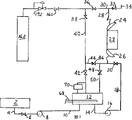
Fig. 1 has described a most preferred embodiment of a system that uses the liquid gas impregnating porous materials according to the principles of the present invention; With
Fig. 2 has described the variation scheme of the equipment shown in Fig. 1.
Identical numeral is represented identical or corresponding part among two figure with the technique of painting.
The invention provides a kind of liquid gas impregnating porous materials of using, and immerse by evaporation Liquefied gas with the expanded method to desired density of porous material. The present invention can be applicable to appoint What expandable porous material expanded. The present invention is particularly useful for tobacco and other smoking materials Material and food comprise the expanded of dry fruit, biltong class and gulch class. The present invention is specially adapted to cigarette Careless is expanded.
The swelling agent that is used for expanded porous materials can be to be gaseous state under the normality of any inertia Fluid namely can not react with porous material or it is had adverse effect and disturbs its predetermined using Any fluid on way. Best inert gas is in the predetermined use of process of the present invention The gas of liquefiable and curing under the temperature and pressure. The typical inert fluid that the present invention uses For air, carbon dioxide, chlorinated hydrocarbon, as refrigerant and be as everyone knows The CFC hydrogen compound in fluorine Lyons, nitrogen, oxygen, argon, hydrogen, helium, ammonia and low alkalinity material, namely The compound that contains 1 to 6 carbon atom is such as methane etc. The mixture of these gases is at it Also can use in the compatible situation. Best inert gas is carbon dioxide, because it is Environmentally safe, liquefy easily and solidify, infiltrate easily the hilum of porous material, and one As, it is not to being had adverse effect by expanded porous material. In the following description, Term " inert gas " is the specific inert gas that represents to be in gaseous state, and term " liquid inert gas " is to describe to be in liquid inert gas.
The present invention is applied to describe with the liquid CO 2 expanding tobacco with it especially, and is right And, be to be understood that process of the present invention and equipment can be used for using any liquefied gas Expanded any porous material.
Referring to Fig. 1, it has described a most preferred embodiment of the present invention, constituting capital equipment element of the present invention is: a liquefied gas holder 2, one liquefied gas process vessel 12, one porous material impregnation chamber 22, an one low-pressure inert gas gatherer 56 and a high-pressure inert gas gatherer 62.The bottom of holder 2 is connected in the suction side of high-pressure pump 8 by pipeline 4, and the flows in the pipeline 4 are by valve 6 controls.The discharge line 10 of pump 8 is connected in the bottom of liquefied gas process vessel 12.Pipeline 14 couples together the suction side of the bottom of process vessel 12 and high-pressure pump 16.The discharge line 18 of pump 16 is connected in the lowermost portion of porous material impregnation chamber 22.Flow in the pipeline 18 is by valve 20 controls.Impregnation chamber 22 is provided with shutoff device 24 and following shutoff device 26.Shutoff device 24 and 26 is respectively applied for the top and the bottom opening of sealing impregnation chamber 22.
Can adopt the holder of traditional bin form to be used for the liquid gas that stocking system is used.Container 2 is designed to bear at least 300 pounds of pressure of flat inch whenever.On the other hand, process vessel 12 is designed to bear the much bigger pressure of pressure in the container 2, and for example it must bear about 1200 pound per square inches or higher pressure.Pump 8 and 16 is conventional cryogenic fluid pump, and being designed to can be at pumping fluid under the high back pressure, for example can 1200 pound per square inches or higher pressure supply liquefied gas.Holder 2 is used for replenishing liquid gas for as required process vessel 12 at dipping process.
Now with tobacco as porous material, as inert gas process of the present invention is described with carbon dioxide.In an exemplary systems, the pressure of the liquefied carbon dioxide in the inert gas holder 2 is about 275 pound per square inches, and equilibrium temperature is about-6F (21 ℃).Liquefied carbon dioxide in process vessel 12 generally remains on pressure and is about poised state under 400 pound per square inches.At the about 17F of equilibrium temperature of 400 pound per square inch pressure carbon dioxides (99 ℃).The temperature of the liquid gas in process in the container 12 may drop to below the equilibrium valve.In this case, the liquid in the necessary heating container 12 gos up to required temperature it.Heater 68 can be used as this purposes.
According to a most preferred embodiment, the bottom shutoff device 26 of impregnation chamber 22 cuts out and seals, and top shutoff device 24 is opened.The tobacco of scheduled volume is packed in the impregnation chamber 22 by shutoff device 24, and this shutoff device cuts out and seals subsequently.Use low pressure CO 2 to purge impregnation chamber 22 then from gatherer 56.When carrying out this step, valve 54,38,46 and 32 is all opened.Other valve keeps closing.Low pressure CO 2 just is transported in the impregnation chamber 22 by pipeline 52,30,40 and 44 from gatherer 56 like this.Carbon dioxide slowly rises in chamber 22, and the air in the chamber 22 and other incondensable gases are driven away by pipeline 28.These gases are discharged in the atmosphere by blow vent 34.
After purge step is finished, valve 32,38 and 46 is closed, and valve 36 is opened.Low pressure CO 2 continues to flow to impregnation chamber 22 by pipeline 52,30 and 28 from gatherer 56, and the pressure in chamber 22 equates with pressure in the gatherer 56.Then valve 54 is closed, and open valve 60.The pressure of carbon dioxide is approximately equal to the pressure in the process vessel 12 in the gatherer 62.One opens valve 60, can realize the pressure balance of gatherer 62 and impregnation chamber 22.When reaching pressure balance, valve-off 60.Increase pressure with gatherer 56 and choose wantonly, promptly impregnation chamber 22 can fully only be pressurizeed with gatherer 62.
In the next stage of this process, liquefied carbon dioxide is sent into chamber 22.This step is by opening valve 38,42 and 20 and start pump 16 and finish.Make valve 36 still keep the opening state of previous step in rapid, and every other valve is still closed.So liquid carbon dioxide flows into chamber 22 by pipeline 14 and 18.Along with the rising of liquid carbon dioxide liquid level in the chamber 22, originally the gaseous carbon dioxide in the chamber 22 is forced through pipeline 28 delivery chamber 22, then enters the vapor space of process vessel 12 through pipeline 30 and 40.In this operational phase, because liquid state and gaseous carbon dioxide are to circulate in a closed system, and the pressure in the closed system is equal everywhere, so the pressure in the process vessel 12 keep substantially constant.When the liquid carbon dioxide in the chamber 22 rose to required liquid level, pump 16 just shut down, and valve 20 is closed.So allow tobacco be immersed in one period predetermined time of staying in the liquid carbon dioxide, this section preset time can be 1 second to 1 hour or longer.General, soak time is several seconds kinds, promptly about 1 to 10 second, just is enough to make enough liquefied carbon dioxides to immerse tobacco to bring about the desired effect.
After impregnation stage is finished, open valve 48, the liquid carbon dioxide in the chamber 22 discharges back process vessel 12 by pipeline 50.Be appreciated that realize that in order to rely on gravity discharging refluxes completely, impregnation chamber 22 must be arranged on the position that is higher than process vessel 12.If not this situation, a pump just must be set in pipeline 50 with liquid carbon dioxide pumped back container 12.Do not come though draw, be appreciated that pipeline 50 can be connected in the suction side of pump 16 yet, draw an arm from pipeline 18 and add a suitable valve, can be used for making liquefied carbon dioxide to flow back to container 12.Equally, also can adopt the device of other equivalences.Along with liquefied carbon dioxide 22 discharges back container 12 from the chamber, gaseous carbon dioxide is forced to flow back to impregnation chamber 22 from the vapor space of container 12 by pipeline 40,30 and 28.In this stage, the pressure in chamber 22 and container 12 and the connecting line keeps substantially constant.
After finishing the impregnation stage of this process of in system shown in Figure 1, being carried out, valve-off 38,42 and 48, and open valve 54.This just makes gaseous carbon dioxide flow out from impregnation chamber 22, enters low pressure gatherer 56 by pipeline 28,30 and 52.Along with carbon dioxide leaves impregnation chamber, indoor pressure descends, and flashes into steam with some inner liquefied carbon dioxides on the hilum of such tobacco, and other then solidify.The gaseous carbon dioxide of overflowing owing to evaporation is recovered in the gatherer 56 equally.Flowing of gaseous carbon dioxide will continue, and the pressure in chamber 22 equates with pressure in the gatherer 56.The additional carbon dioxide of 22 recovery from the chamber can be established an aspiration pump (not shown) on pipeline 30 if desired, further extracts the carbon dioxide in the chamber 22.Purge general enough next circulations of the amount of the carbon dioxide of collecting from chamber 22 and the usefulness of pressurization steps.If desired, can replenish carbon dioxide for gatherer 56 and 62 from the external source (not shown).Finish carbon dioxide from chamber 22 after the conveying of container 56, valve-off 54 and 36, and open valve 32 makes the residual carbon dioxide in the chamber 22 be discharged in the atmosphere like this.
When chamber 22 reaches atmospheric pressure, can open its lower end door 26, from indoor taking-up tobacco.After taking out tobaccos in the chamber 22, can be by use hot gas, for example air or steam and Air mixing gas heat tobacco and make it expansion.The heating tobacco can make the solidified carbon dioxide distillation in its hilum, and any residual liquefied carbon dioxide evaporation in the hilum.Because distillation and evaporation, the gas in the hilum increases suddenly, makes expanding tobacco.
Using increases pressure in the chamber 22 from the carbon dioxide of high pressure collecting device 62 and will consume carbon dioxide in this container.Gatherer 62 can and be delivered to container 62 with it by a part of carbon dioxide in the compression gatherer 56 and re-fill carbon dioxide.This realizes with compressor 66.
In some cases, may needn't or not need do not reclaim the residual carbon dioxide of staying behind the soaking step in the chamber 22.In this case, comprise gatherer 56 and 62 and the recovery system of compressor 66 can cancel, and replace outside carbon dioxide.Fig. 2 has described this embodiment of the present invention.Equipment among Fig. 2 is identical with equipment shown in Figure 1, and just gatherer 56 and 62 is replaced by container 162, and container 162 is stored carbon dioxide, and its pressure is equal to or greater than the pressure in the process vessel 12; Valve 60 has become valve 160, and is provided with a pressure regulator 172 on the pipeline 30 between valve 160 and the container 162.
In the process of the present invention as shown in Figure 2, the same with the method described in Fig. 1, tobacco is packed into after the impregnation chamber 22, with impregnation chamber 22 sealings. Open valve 32,38,46 and 160, and pressure regulator 172 is set in enough low pressure, so that slowly purge chamber 22.Every other valve in these systems is all closed.So carbon dioxide enters impregnation chamber 22 from container 162 through pipeline 30,40 and 44.Carbon dioxide slowly rises in chamber 22, forces air and other incondensable gases to be discharged in 22 from the chamber and enters pipeline 28.The carbon dioxide pipeline 30 of flowing through leaves system by blow vent 34 then.When purge step was finished, valve-off 32,38,46 was opened valve 36, and the pressure of pressure regulator 172 is adjusted to the pressure that is equivalent to carbon dioxide in the process vessel 12.Carbon dioxide passes through pipeline 30 and 28 inlet chambers 22 from container 162 then.Allow carbon dioxide continue to flow into chamber 22, the pressure in chamber 22 reaches the pressure in the process vessel 12.At this moment, valve-off 160, and open valve 20,38,42, and start pump 16, make liquid CO 2 flow into chamber 22 with the tobacco in the impregnation chamber.Soaking step in the method for system shown in Figure 2 is the same with the method for system shown in Figure 1.After the soaking step of finishing tobacco and the discharging of impregnation chamber 22 subsequently, open valve 32, chamber 22 by pipeline 28 and 30 and blow vent 34 communicate all the other steps in this method and identical at the described method of the system of Fig. 1 with atmosphere.
Though do not have method economy shown in Figure 1 from the method shown in the angle Fig. 2 that uses, to compare with the system of Fig. 1, equipment funds shown in Figure 2 consume low, and simple to operate.
After impregnation cycles finishes in the system of Fig. 1 or Fig. 2, repeat steps such as the above-mentioned tobacco of packing into, purging, pressure balance, dipping and taking-up tobacco in this technical process and constantly repeat.If desired, this process can be carried out with a plurality of impregnation chamber.In this case, generally need use impregnation chamber in the mode of alternate cycles, promptly when to indoor packing into during tobacco, the tobacco in another impregnation chamber is by with the liquid carbon dioxide dipping, and the 3rd dipping chamber is drained, or the like.In other words, all be in different phase in the impregnation cycles in arbitrary given each impregnation chamber of the moment.
Can clearly find from above description dipping process, the pressure in the process vessel 12 in the impregnation cycles process because to remove the variation that gas takes place very little because purge and pressure equalization step in from this container, not extracting carbon dioxide.Correspondingly, need obviously reduce by the heat that heater 68 offers container 12 for keeping this container to be in basic constant voltage.Like this, with respect to the process of prior art, the present invention greatly reduces operating cost.
Though emphasis of the present invention has been described certain embodiments, be appreciated that the many variations that it is contemplated that out these embodiment.For example, as above mentioned, can use a plurality of steepers simultaneously, or system can use the liquid gas beyond the carbon dioxide, also can adopt to be different from the apparatus arrangement shown in the figure.Similarly, process of the present invention can be used for the expanded porous material that removes tobacco.And, if desired, the condensation of gas from high pressure collecting device 62 can be become liquefied gas and send back to reservoir vessel 2.Scope of the present invention is only limited by the range of claim.
Claims (15)
1. method that is used for expanded porous materials comprises:
(a) porous material is packed into a sealable steeper that a fluid import and fluid issuing arranged, described fluid issuing is positioned at the top of described impregnation chamber;
(b) with impregnation chamber and atmospheric isolation;
(c) with the hermetically sealed impregnation chamber of inert gas purge;
It is characterized in that, also comprise:
(d) with described inert gas the steeper that has purged totally is forced into the pressure that is substantially equal in the process vessel, this process vessel contains the described gaseous state inert gas in a basic balance and the mixture of liquid inert gas;
(e) liquefied gas is delivered to the steeper that has pressurizeed from described process vessel by described fluid inlet, makes the inert gas be delivered to the evaporating space of described process vessel by described fluid issuing from described impregnation chamber simultaneously;
(f) liquefied gas is retained in the sufficiently long time in the described impregnation chamber, so that liquefied gas penetrates in the hilum of described porous material;
(g) described liquefaction noble gas body is delivered to described process vessel by described fluid inlet, makes the inert gas in the described process vessel be delivered to described steeper simultaneously by described fluid issuing;
(h) reduce the interior pressure of described steeper; With
(i) fully heat described porous material,, make described porous material expanded thus so that be included in the liquefaction in the described porous material hilum and solidify the inert gas evaporation.
2. the method for claim 1 is characterized in that, described inert gas is to select from the mixture of air, carbon dioxide, nitrogen, oxygen, argon, halogenated hydrocarbon, ammonia, low alkalinity material and these gases.
3. the method for claim 1 is characterized in that, described porous material is to select from fruit, vegetables, meat, cereal and tobacco.
4. the method for claim 1 is characterized in that, described porous material is a tobacco.
5. as each the described method in the claim 1,3 or 4, it is characterized in that described inert gas is a carbon dioxide.
6. as each the described method in the claim 1,3 or 4, it is characterized in that the gas that is used for purging described impregnation chamber obtains from a low-pressure inert gas reservoir vessel.
7. method as claimed in claim 6 is characterized in that, the pressure in the described low-pressure inert gas reservoir vessel keeps below the pressure in the described process vessel.
8. as each the described method in the claim 1,3 or 4, it is characterized in that the inert gas that is used for increasing the steeper internal pressure obtains from a high-pressure inert gas reservoir vessel.
9. method as claimed in claim 8 is characterized in that, the pressure in the described high-pressure inert gas reservoir vessel is equal to or higher than the pressure in the described process vessel.
10. method as claimed in claim 9 is characterized in that, the inert gas that discharges from described steeper in depressurization steps is passed into described low-pressure inert gas reservoir vessel.
11. method as claimed in claim 10, it is characterized in that, inert gas in described high-pressure inert gas reservoir vessel be by compression from the gas in the described low-pressure inert gas reservoir vessel, and the gas that will compress is delivered to described high-pressure inert gas reservoir vessel and obtains replenishing.
12. be used for that the constant substantially equipment of temperature of described liquid gas comprises with a kind of liquid gas expanded porous materials:
(a) a high-pressure impregnation container (22), it be useful on porous material pack into described steeper (22), superposed sealing device (24) and being used for porous material from described steeper (22) sealing device that take out, that be positioned at the bottom;
(b) and the device pipeline connection between valve (36) and (38), that be used for purging described steeper (22) with low-pressure inert gas;
It is characterized in that, also comprise:
(c) a liquefied gas process vessel (12), its upper space links to each other with high-pressure impregnation container (22) top with (28) by valve (42), pipeline (40), valve (38) and (36), the pipeline (30) that links to each other successively; Its upper space also links to each other with the bottom of high-pressure impregnation container (22) by pipeline (50), the valve (48) that links to each other successively; And lower space links to each other by pipeline (14), pump (16), pipeline (18) and the bottom of valve (20) with high-pressure impregnation container (22) that links to each other successively; And the end that a valve (44) is arranged is connected on the pipeline (40) between valve (38) and (42), and the other end is connected on the pipeline between valve (20) and (48);
(d) be independent of described liquefied gas process vessel (12), and valve (36) and (38) between pipeline connection, be used for described steeper (22) being forced into the device that pressure is substantially equal to the equalizing pressure of described liquefied gas process vessel (12) with high-pressure inert gas; With
(e) make the open to atmosphere device of described steeper (22) (34) by the valve (32) that is communicated with pipeline (28).
13. equipment as claimed in claim 12 is characterized in that, above-mentioned (b) described device is the low-pressure inert gas gatherer (56) by the pipeline connection between valve (54), pipeline (52) and valve (36) and (38); And above-mentioned (d) described device is the high-pressure inert gas gatherer (62) by the pipeline connection between valve (60), pipeline (58) and valve (36) and (38).
14. equipment as claimed in claim 13, it is characterized in that, further comprise one by one end by the compressor (66) that pipeline (64) is communicated with low-pressure inert gas gatherer (56), the other end is communicated with high-pressure inert gas gatherer (62), be delivered to the high-pressure inert gas gatherer (62) of the described described steeper (22) that is used to pressurize with the inert gas that is used for compressing inert gas, also will compress from described steeper (22).
15. equipment as claimed in claim 12, it is characterized in that the device of described device that is used to purge described steeper (22) and the described described steeper (22) that is used to pressurize comprises the high-pressure inert gas storage device (162), a pressure-regulating device (172) and the other end that link to each other successively and the valve (160) of the pipeline connection between valve (36) and (38).
Applications Claiming Priority (2)
| Application Number | Priority Date | Filing Date | Title |
|---|---|---|---|
| US07/650,322 | 1991-02-04 | ||
| US07/650,322 US5143096A (en) | 1991-02-04 | 1991-02-04 | Method and apparatus for expanding cellular materials |
Publications (2)
| Publication Number | Publication Date |
|---|---|
| CN1063809A CN1063809A (en) | 1992-08-26 |
| CN1031486C true CN1031486C (en) | 1996-04-10 |
Family
ID=24608407
Family Applications (1)
| Application Number | Title | Priority Date | Filing Date |
|---|---|---|---|
| CN92100722A Expired - Fee Related CN1031486C (en) | 1991-02-04 | 1992-02-01 | Improved method and apparatus for expanding cellular materials |
Country Status (17)
| Country | Link |
|---|---|
| US (1) | US5143096A (en) |
| EP (1) | EP0500226B2 (en) |
| JP (1) | JPH0515360A (en) |
| KR (1) | KR950008548B1 (en) |
| CN (1) | CN1031486C (en) |
| AT (1) | ATE125672T1 (en) |
| AU (1) | AU644934B2 (en) |
| CA (1) | CA2060219C (en) |
| DE (1) | DE69203744T3 (en) |
| DK (1) | DK0500226T4 (en) |
| ES (1) | ES2075606T5 (en) |
| GR (1) | GR3017189T3 (en) |
| ID (1) | ID835B (en) |
| IE (1) | IE68855B1 (en) |
| NZ (1) | NZ241484A (en) |
| TR (1) | TR26134A (en) |
| ZA (1) | ZA92520B (en) |
Families Citing this family (24)
| Publication number | Priority date | Publication date | Assignee | Title |
|---|---|---|---|---|
| US5259403A (en) * | 1992-03-18 | 1993-11-09 | R. J. Reynolds Tobacco Company | Process and apparatus for expanding tobacco cut filler |
| US5483977A (en) * | 1993-06-14 | 1996-01-16 | R. J. Reynolds Tobacco Company | Tobacco expansion processes and apparatus |
| GB9402473D0 (en) * | 1994-02-09 | 1994-03-30 | Mg Gas Products Ltd | Dry ice expanded tobacco |
| US5819754A (en) * | 1995-12-29 | 1998-10-13 | R. J. Reynolds Tobacco Company | Tobacco expansion processes and apparatus |
| US5693354A (en) * | 1996-05-01 | 1997-12-02 | L'air Liquide, Societe Anonyme Pour L'etude Et, L'exploitation Des Procedes Georges Claude | Method of disinfecting fresh vegetables by processing the same with a liquid containing a mixture of argon:carbon dioxide |
| JP3165791B2 (en) * | 1997-03-27 | 2001-05-14 | 日本たばこ産業株式会社 | Method for producing expanded tobacco material |
| US6067994A (en) * | 1997-10-07 | 2000-05-30 | R.J. Reynolds Tobacco Company | Tobacco expansion batch forming, unloading and expansion agent purging process and apparatus |
| FR2770171B1 (en) * | 1997-10-27 | 1999-11-19 | Commissariat Energie Atomique | METHOD AND INSTALLATION FOR TREATING POROUS MATERIAL WITH AN IMPREGNATION PRODUCT |
| US6209546B1 (en) * | 1998-11-30 | 2001-04-03 | Truman W. Ellison | Apparatus and method for improved hydrate formation and improved efficiency of recovery of expansion agent in processes for expanding tobacco and other agricultural products |
| US6575170B1 (en) * | 2000-11-27 | 2003-06-10 | Ravi Prasad | Method and apparatus for expanding tobacco material |
| US7726320B2 (en) | 2006-10-18 | 2010-06-01 | R. J. Reynolds Tobacco Company | Tobacco-containing smoking article |
| WO2008141233A1 (en) * | 2007-05-09 | 2008-11-20 | Nestec S.A. | Freeze-dried, aerated dairy or dairy-substitute compositions and methods of making thereof |
| US20110300255A9 (en) * | 2007-05-09 | 2011-12-08 | Nestec S.A. | Freeze-dried, dairy or dairy-substitute compositions and methods of using same |
| ES2727417T3 (en) * | 2007-05-09 | 2019-10-16 | Nestle Sa | The use of a fruit or vegetable composition in a process for the preparation of a lyophilized, aerated, fruit or vegetable product |
| CN101991183B (en) * | 2009-08-11 | 2013-01-09 | 北京达特烟草成套设备技术开发有限责任公司 | Cut tobacco impregnating process and equipment |
| US20130255702A1 (en) | 2012-03-28 | 2013-10-03 | R.J. Reynolds Tobacco Company | Smoking article incorporating a conductive substrate |
| JP2016105701A (en) * | 2013-03-28 | 2016-06-16 | 日本たばこ産業株式会社 | Method for preparing tobacco filler having low balkiness |
| US9839238B2 (en) | 2014-02-28 | 2017-12-12 | Rai Strategic Holdings, Inc. | Control body for an electronic smoking article |
| CN105852183B (en) * | 2016-04-20 | 2018-05-08 | 陕西科技大学 | Fruits and vegetables Thief zone airflow puffing device and method |
| CN108208908A (en) * | 2017-05-12 | 2018-06-29 | 山东中烟工业有限责任公司 | A system and method for improving the safe operation of an expansion wire impregnator |
| JP2019154349A (en) * | 2018-03-14 | 2019-09-19 | 株式会社リコー | Animal or plant tissue, cell breaking method for animal or plant tissue, and cell breaking device for animal or plant tissue |
| TWI859157B (en) * | 2018-09-19 | 2024-10-21 | 美商摩丁有限責任公司 | Cooling system for calculating components |
| US12022859B2 (en) | 2019-07-18 | 2024-07-02 | R.J. Reynolds Tobacco Company | Thermal energy absorbers for tobacco heating products |
| CN114100696B (en) * | 2020-08-26 | 2022-11-25 | 宁波方太厨具有限公司 | Device for loading active components on catalyst module |
Family Cites Families (9)
| Publication number | Priority date | Publication date | Assignee | Title |
|---|---|---|---|---|
| FR2259546B1 (en) * | 1974-02-05 | 1979-08-24 | Irco Inc | |
| US4340073A (en) * | 1974-02-12 | 1982-07-20 | Philip Morris, Incorporated | Expanding tobacco |
| US4235250A (en) * | 1978-03-29 | 1980-11-25 | Philip Morris Incorporated | Process for the expansion of tobacco |
| US4165618A (en) * | 1978-04-24 | 1979-08-28 | Lewis Tyree Jr | Treatment with liquid cryogen |
| US4561453A (en) * | 1981-12-16 | 1985-12-31 | Rothchild Ronald D | Treatment of tobacco under pressure in a continuous process |
| US4460000A (en) * | 1982-06-14 | 1984-07-17 | The Boc Group, Inc. | Vacuum and gas expansion of tobacco |
| US4870980A (en) * | 1987-04-10 | 1989-10-03 | R. J. Reynolds Tobacco Company | Tobacco expansion process and apparatus |
| CA1328064C (en) * | 1987-07-27 | 1994-03-29 | Masao Kobari | Apparatus for expanding material for foodstuffs, favorite items and the like |
| US4946697A (en) * | 1988-11-25 | 1990-08-07 | University Of Kentucky Research Foundation | Puffing biological material |
-
1991
- 1991-02-04 US US07/650,322 patent/US5143096A/en not_active Expired - Lifetime
-
1992
- 1992-01-24 ZA ZA92520A patent/ZA92520B/en unknown
- 1992-01-28 AU AU10531/92A patent/AU644934B2/en not_active Ceased
- 1992-01-29 DE DE69203744T patent/DE69203744T3/en not_active Expired - Fee Related
- 1992-01-29 ES ES92300767T patent/ES2075606T5/en not_active Expired - Lifetime
- 1992-01-29 AT AT92300767T patent/ATE125672T1/en not_active IP Right Cessation
- 1992-01-29 CA CA002060219A patent/CA2060219C/en not_active Expired - Fee Related
- 1992-01-29 DK DK92300767T patent/DK0500226T4/en active
- 1992-01-29 EP EP92300767A patent/EP0500226B2/en not_active Expired - Lifetime
- 1992-01-31 NZ NZ241484A patent/NZ241484A/en not_active IP Right Cessation
- 1992-01-31 ID IDP205792A patent/ID835B/en unknown
- 1992-02-01 CN CN92100722A patent/CN1031486C/en not_active Expired - Fee Related
- 1992-02-01 KR KR1019920001615A patent/KR950008548B1/en not_active Expired - Fee Related
- 1992-02-03 IE IE920347A patent/IE68855B1/en not_active IP Right Cessation
- 1992-02-04 TR TR92/0120A patent/TR26134A/en unknown
- 1992-02-04 JP JP4019222A patent/JPH0515360A/en active Pending
-
1995
- 1995-08-23 GR GR950402301T patent/GR3017189T3/en unknown
Also Published As
| Publication number | Publication date |
|---|---|
| DK0500226T4 (en) | 2002-08-05 |
| US5143096A (en) | 1992-09-01 |
| ES2075606T5 (en) | 2003-01-16 |
| JPH0515360A (en) | 1993-01-26 |
| KR920016136A (en) | 1992-09-24 |
| IE68855B1 (en) | 1996-07-24 |
| TR26134A (en) | 1995-02-15 |
| KR950008548B1 (en) | 1995-08-03 |
| EP0500226B2 (en) | 2002-05-02 |
| EP0500226B1 (en) | 1995-08-02 |
| ZA92520B (en) | 1993-01-27 |
| AU644934B2 (en) | 1993-12-23 |
| CA2060219C (en) | 1997-03-18 |
| EP0500226A1 (en) | 1992-08-26 |
| DE69203744T3 (en) | 2002-11-21 |
| IE920347A1 (en) | 1992-08-12 |
| CA2060219A1 (en) | 1992-08-05 |
| DE69203744T2 (en) | 1996-01-18 |
| GR3017189T3 (en) | 1995-11-30 |
| ATE125672T1 (en) | 1995-08-15 |
| DK0500226T3 (en) | 1995-09-18 |
| NZ241484A (en) | 1993-08-26 |
| ID835B (en) | 1996-07-29 |
| ES2075606T3 (en) | 1995-10-01 |
| DE69203744D1 (en) | 1995-09-07 |
| CN1063809A (en) | 1992-08-26 |
| AU1053192A (en) | 1992-08-06 |
Similar Documents
| Publication | Publication Date | Title |
|---|---|---|
| CN1031486C (en) | Improved method and apparatus for expanding cellular materials | |
| US4165618A (en) | Treatment with liquid cryogen | |
| US5649552A (en) | Process and apparatus for impregnation and expansion of tobacco | |
| CA1076913A (en) | Methods and apparatus for expanding organic substances | |
| US5283035A (en) | Method for recovering a sterilizing gas | |
| KR910000803B1 (en) | How to increase the filling capacity of cigarettes | |
| NO178992B (en) | Method of expansion of tobacco | |
| WO2004083713A3 (en) | Compression method and filling station | |
| US5076293A (en) | Process and apparatus for the treatment of tobacco material | |
| AU748071B2 (en) | Apparatus and method for improved hydrate formation and improved efficiency of recovery of expansion agent in processes for expanding tobacco and other agricultural products | |
| EP0706331B1 (en) | Improvements in or relating to processing of smoking material | |
| AU644736B2 (en) | Expanding apparatus for agricultural product or the like | |
| CN1030749C (en) | Puffing device for tobacco material | |
| JP5650321B2 (en) | Tobacco expansion method and apparatus | |
| Cope | Production of low pressures with sorption pumps | |
| GB2108254A (en) | Method of drying pipelines | |
| JP3154811B2 (en) | Puffing equipment for agricultural products | |
| Cheng et al. | Obtaining low pressures with cryosorption pumps |
Legal Events
| Date | Code | Title | Description |
|---|---|---|---|
| C10 | Entry into substantive examination | ||
| SE01 | Entry into force of request for substantive examination | ||
| C06 | Publication | ||
| PB01 | Publication | ||
| C14 | Grant of patent or utility model | ||
| GR01 | Patent grant | ||
| C15 | Extension of patent right duration from 15 to 20 years for appl. with date before 31.12.1992 and still valid on 11.12.2001 (patent law change 1993) | ||
| OR01 | Other related matters | ||
| C19 | Lapse of patent right due to non-payment of the annual fee | ||
| CF01 | Termination of patent right due to non-payment of annual fee |