CN103166312A - Low voltage long distance intelligent residential district motive power prepayment device - Google Patents
Low voltage long distance intelligent residential district motive power prepayment device Download PDFInfo
- Publication number
- CN103166312A CN103166312A CN2011104146723A CN201110414672A CN103166312A CN 103166312 A CN103166312 A CN 103166312A CN 2011104146723 A CN2011104146723 A CN 2011104146723A CN 201110414672 A CN201110414672 A CN 201110414672A CN 103166312 A CN103166312 A CN 103166312A
- Authority
- CN
- China
- Prior art keywords
- contactor
- wireless controller
- intelligent
- residential district
- control
- Prior art date
- Legal status (The legal status is an assumption and is not a legal conclusion. Google has not performed a legal analysis and makes no representation as to the accuracy of the status listed.)
- Granted
Links
Images


Classifications
-
- Y—GENERAL TAGGING OF NEW TECHNOLOGICAL DEVELOPMENTS; GENERAL TAGGING OF CROSS-SECTIONAL TECHNOLOGIES SPANNING OVER SEVERAL SECTIONS OF THE IPC; TECHNICAL SUBJECTS COVERED BY FORMER USPC CROSS-REFERENCE ART COLLECTIONS [XRACs] AND DIGESTS
- Y02—TECHNOLOGIES OR APPLICATIONS FOR MITIGATION OR ADAPTATION AGAINST CLIMATE CHANGE
- Y02B—CLIMATE CHANGE MITIGATION TECHNOLOGIES RELATED TO BUILDINGS, e.g. HOUSING, HOUSE APPLIANCES OR RELATED END-USER APPLICATIONS
- Y02B90/00—Enabling technologies or technologies with a potential or indirect contribution to GHG emissions mitigation
- Y02B90/20—Smart grids as enabling technology in buildings sector
-
- Y—GENERAL TAGGING OF NEW TECHNOLOGICAL DEVELOPMENTS; GENERAL TAGGING OF CROSS-SECTIONAL TECHNOLOGIES SPANNING OVER SEVERAL SECTIONS OF THE IPC; TECHNICAL SUBJECTS COVERED BY FORMER USPC CROSS-REFERENCE ART COLLECTIONS [XRACs] AND DIGESTS
- Y04—INFORMATION OR COMMUNICATION TECHNOLOGIES HAVING AN IMPACT ON OTHER TECHNOLOGY AREAS
- Y04S—SYSTEMS INTEGRATING TECHNOLOGIES RELATED TO POWER NETWORK OPERATION, COMMUNICATION OR INFORMATION TECHNOLOGIES FOR IMPROVING THE ELECTRICAL POWER GENERATION, TRANSMISSION, DISTRIBUTION, MANAGEMENT OR USAGE, i.e. SMART GRIDS
- Y04S40/00—Systems for electrical power generation, transmission, distribution or end-user application management characterised by the use of communication or information technologies, or communication or information technology specific aspects supporting them
- Y04S40/12—Systems for electrical power generation, transmission, distribution or end-user application management characterised by the use of communication or information technologies, or communication or information technology specific aspects supporting them characterised by data transport means between the monitoring, controlling or managing units and monitored, controlled or operated electrical equipment
- Y04S40/126—Systems for electrical power generation, transmission, distribution or end-user application management characterised by the use of communication or information technologies, or communication or information technology specific aspects supporting them characterised by data transport means between the monitoring, controlling or managing units and monitored, controlled or operated electrical equipment using wireless data transmission
Landscapes
- Remote Monitoring And Control Of Power-Distribution Networks (AREA)
Abstract
本发明是关于对低压小动力用户实行远程抄表及远程预付费的智能控制装置,包括GPRS通讯功能的智能终端控制设备,GPRS通讯功能的智能终端控制设备分别与若干个用户端连接,用户端包括无线控制器、接触器、信号指示装置、仪表装置和隔离刀闸,无线控制器与GPRS通讯功能的智能终端控制设备相对应,无线控制器分别与接触器、信号指示装置和仪表装置连接,隔离刀闸分别与仪表装置和无线控制器连接。本发明具有实时抄表功能、预付费功能、远程控制功能、实时监控功能、催告警功能。
The invention relates to an intelligent control device for remote meter reading and remote prepayment for low-voltage small power users, including an intelligent terminal control device with a GPRS communication function. The intelligent terminal control device with a GPRS communication function is connected to several user terminals respectively. Including wireless controller, contactor, signal indicating device, instrument device and isolating switch. The wireless controller corresponds to the intelligent terminal control equipment with GPRS communication function. The wireless controller is respectively connected with the contactor, signal indicating device and instrument device. The isolation switch is connected with the instrument device and the wireless controller respectively. The invention has the functions of real-time meter reading, prepayment, remote control, real-time monitoring and alarming.
Description
技术领域 technical field
本发明是关于对低压小动力用户实行远程抄表及远程预付费的智能控制装置。 The invention relates to an intelligent control device for remote meter reading and remote prepayment for low-voltage small power users. the
背景技术 Background technique
目前对于低压小动力用户用电管理及控制装置有两种情况。 At present, there are two situations for low-voltage small power users' electricity management and control devices. the
一种为人工抄表及人工现场控制装置,该装置为每月由抄表人员到现场人工抄读电表示数,然后依据该示数计算用户上月所发生的电费。当用户发生拖欠电费时,需由抄表人员电话通知或下发欠费通知单通知用户及时交费,若用户仍然不能按时交费,需由抄表人员到现场人工停电。当用户交纳了电费后,还需抄表人员到现场人工送电。该种方式工作流程繁琐、浪费人力资源、工作效率低还容易造成电费拖欠的情况。该装置所用主要部件有箱体、电能表、负荷开关。 One is a manual meter reading and manual on-site control device. The device reads the electricity indications manually on the spot every month, and then calculates the electricity bills incurred by the user last month based on the indications. When the user is in arrears of electricity bills, the meter reading personnel need to call or issue an arrears notice to notify the user to pay the fee in time. If the user still cannot pay the fee on time, the meter reading personnel must go to the site to manually cut off the power. After the user pays the electricity fee, the meter reader needs to go to the scene to send electricity manually. This method has cumbersome work process, waste of human resources, low work efficiency and easy to cause electricity bill arrears. The main components used in the device are box body, electric energy meter and load switch. the
另一种方式为人工抄表、IC卡方式预付费自动控制装置。该装置由用户预先到供电营业厅预交电费,并把预购电量充到IC卡内,然后持卡到现场把预购电量充到控制装置内。随着用户用电的增加,预购的电量而逐渐减少。当所剩电量不多时,用户可事先再次持卡到供电营业厅预购电量,并及时充到控制装置内。若用户没有及时去购电或没有及时充值,当所剩电量用完时,控制装置就会发出跳闸指令而跳闸。供电公司对该用户电费的实际结算仍然靠抄表人员每月到现场抄读电表示数。该装置所用主要部件有箱体、电能表、接触器、带有IC卡读卡器的控制器、负荷开关。 Another way is manual meter reading, IC card mode prepaid automatic control device. The device requires the user to pre-pay the electricity fee at the power supply business hall, and charge the pre-purchased electricity into the IC card, and then take the card to the scene to charge the pre-purchased electricity into the control device. As the user's electricity consumption increases, the pre-purchased electricity will gradually decrease. When the remaining power is not much, the user can hold the card again in advance to the power supply business hall to pre-purchase the power, and charge it to the control device in time. If the user fails to purchase electricity or recharge in time, when the remaining electricity is used up, the control device will issue a trip command to trip. The actual settlement of the user's electricity bill by the power supply company still depends on the meter reading personnel to go to the scene to read the meter every month. The main components used in the device include a box body, an electric energy meter, a contactor, a controller with an IC card reader, and a load switch.
该种方式的不足之处: Disadvantages of this method:
1仍然需要抄表人员每月到现场抄表。 1. Meter reading personnel still need to go to the site to read the meter every month.
2、用户需要持卡到营业厅预购电量,且卡容易丢失。 2. Users need to hold the card to the business hall to pre-purchase electricity, and the card is easy to lose. the
3、读卡器容易损坏,造成不读卡、不识卡而不能充值。 3. The card reader is easily damaged, resulting in failure to recharge due to failure to read or recognize the card. the
4、对用户用电情况不能时实监控。 4. The user's electricity consumption cannot be monitored in real time. the
发明内容 Contents of the invention
由于现有技术不能从根本上解决人工抄表问题,不能有效实行预付费,不能对用户用电情况时实监控,自动化程度不高,系统设备可靠性、稳定性差,防窃电功能差等问题存在,因此需要对现有技术条件进行升级,彻底解决人工抄表,真正实现预付费,有效杜绝电费拖欠,提高自动化水平,防止窃电行为发生,提高系统设备可靠性与稳定性,本发明提供一种低压远程智能小区动力预付费装置。 Because the existing technology cannot fundamentally solve the problem of manual meter reading, it cannot effectively implement prepayment, it cannot monitor the user's electricity consumption in real time, the degree of automation is not high, the reliability and stability of the system equipment are poor, and the anti-theft function is poor. Existence, so it is necessary to upgrade the existing technical conditions, completely solve the manual meter reading, truly realize prepayment, effectively eliminate the arrears of electricity charges, improve the automation level, prevent electricity theft, and improve the reliability and stability of system equipment. The invention provides A low-voltage remote intelligent community power prepayment device. the
本发明将采取以微型智能控制器为核心,以CJ20S型交流接触器为控制手段,以信号指示灯为信息传递,以TM-K1型智能表箱控制装置管理窃电行为发生,多技术、多手段、综合性智能控制装置。 The present invention will take the micro-intelligent controller as the core, use the CJ20S AC contactor as the control means, use the signal indicator light as the information transmission, and use the TM-K1 intelligent meter box control device to manage the occurrence of electricity theft. means, comprehensive intelligent control device. the
微型控制器是具有GPRS通讯功能的智能终端控制设备,它具有实时抄表功能、预付费功能、远程控功能、实时监控功能、催费告警功能。 Microcontroller is an intelligent terminal control device with GPRS communication function. It has real-time meter reading function, prepayment function, remote control function, real-time monitoring function, and payment reminder and alarm function. the
CJ20S型交流接触器是具有电子闭锁功能的交流接触器,它具有跳闸、合闸两个控制线圈。当吸合线圈通电时,铁芯吸合并锁扣,主电路闭合投入运行,线圈瞬时释放;当断开主电路时,接通锁扣控制装置,接触器释放,主电路断开。在工作过程中,接触器控制回路不消耗电能,故称全节能无压型交流接触器。该设备在本发明中起到断开与闭合主电路的作用。 CJ20S AC contactor is an AC contactor with electronic locking function, and it has two control coils for tripping and closing. When the pull-in coil is energized, the iron core is attracted and locked, the main circuit is closed and put into operation, and the coil is released instantaneously; when the main circuit is disconnected, the lock control device is connected, the contactor is released, and the main circuit is disconnected. During the working process, the control circuit of the contactor does not consume electric energy, so it is called a full energy-saving non-voltage AC contactor. This device plays the role of opening and closing the main circuit in the present invention. the
控制按钮在本发明中起到闭合主电路的作用,它与控制器分别作用于交流接触器的合闸线圈与跳闸线圈,从而实现主电路的闭合与断开。 The control button plays the role of closing the main circuit in the present invention, and it and the controller respectively act on the closing coil and the tripping coil of the AC contactor, thereby realizing closing and disconnecting of the main circuit. the
信号指示灯在本发明中起到信息传递作用,它分为运行指示灯、跳闸指示灯、报警指示灯、允许合闸指示灯。当运行指示灯亮时,说明主电路运行正常。当运行指示灯熄灭时,说明主电路已断开或线路停电;当报警指示灯点亮时,说明用户所剩电量已经达到报警门限,通知用户尽快去营业厅预交电费。当用户所剩电量大于报警门限时,该指示灯为熄灭状态;当跳闸指示灯点亮时,说明用户所剩电量已用完,接触器已跳闸,主电路已断开。当接触器闭合、主电路运行时,该指示灯为熄灭状态;当允许合闸指示灯点亮时,说明此时用户可以通过控制按钮进行合闸。若该灯没有被点亮时,按动控制按钮也无法进行合闸。 Signal indicator lights play a role in information transmission in the present invention, and it is divided into operation indicator lights, trip indicator lights, alarm indicator lights, and switch-on indicator lights allowed. When the running indicator light is on, it means that the main circuit is running normally. When the running indicator light is off, it means that the main circuit has been disconnected or the line is out of power; when the alarm indicator light is on, it means that the remaining power of the user has reached the alarm threshold, and the user is notified to go to the business hall to prepay the electricity fee as soon as possible. When the user's remaining power is greater than the alarm threshold, the indicator light is off; when the trip indicator is on, it means that the user's remaining power has been used up, the contactor has tripped, and the main circuit has been disconnected. When the contactor is closed and the main circuit is running, the indicator light is off; when the closing indicator light is on, it means that the user can close the switch through the control button. If the light is not on, the switch cannot be closed by pressing the control button. the
TM-K1型控制装置是装配在带有分励或施压线圈断路器的计量箱内。当非法开启计量箱门时,控制装置带电工作,数秒内断路器跳闸,且无法自行恢复,需电管人员持电子密钥解码后才能恢复送电,从而杜绝用户私自开启计量箱门进行窃电行为的发生。 The TM-K1 type control device is assembled in a metering box with a shunt or pressure coil circuit breaker. When the door of the metering box is opened illegally, the control device will work with power on, and the circuit breaker will trip within a few seconds, and cannot be restored by itself. The power supply can only be resumed after the electronic key is decoded by the electrician, so as to prevent the user from opening the door of the metering box privately to steal electricity. behavior occurs. the
采用上述技术方案,本发明有以下优点:当用户通过供电营业厅购买电量后,工作人员可以通过GPRS网络把用户购买的电量随时下发到控制器内,而不再使用IC卡交费充值。当每月抄表日需要抄读电表示数时,抄表员可以通过系统主站、利用GPRS网络实时抄读电表示数,可免去抄表员到现场抄读电表的工作。当用户剩余电量达到报警门限时,控制器就会发出报警指令,使信号指示装置出声光报警,及时通知用户预交电费。同时系统主站也会根据控制器上报的剩余电量及时向用户发出短信,以告知用户所剩的电量,可免去抄表员到现场下发电费通知单。当用户剩余电量用完时,控制器就会发出跳闸指令,接触器得到指令后就会跳闸而断电,从而杜绝用户拖欠电费的发生。当用户因电量用完断电后,在没有预交费的情况下,用户无法自行送电。当用户预交电费并下发后,用户可以自行启动按钮而送电,从而实现管理人员不再去现场停送电的功能。 Adopting the above technical solution, the present invention has the following advantages: after the user purchases electricity through the power supply business hall, the staff can send the purchased electricity to the controller at any time through the GPRS network, instead of using the IC card to pay and recharge. When it is necessary to read the electricity indication on the monthly meter reading day, the meter reader can read the electricity indication in real time through the system master station and the GPRS network, which can save the meter reader from reading the electricity meter on site. When the user's remaining power reaches the alarm threshold, the controller will send out an alarm command, causing the signal indicating device to issue an audible and visual alarm, and promptly notify the user to prepay the electricity fee. At the same time, the main station of the system will also send a short message to the user in time according to the remaining power reported by the controller to inform the user of the remaining power, which can save the meter reader from going to the site to issue a power generation fee notice. When the user's remaining power is used up, the controller will issue a trip command, and the contactor will trip and cut off the power after receiving the command, so as to prevent the user from defaulting on electricity bills. When the user cuts off the power due to running out of power, the user cannot send electricity by himself without prepayment. After the user pays the electricity fee in advance and sends it out, the user can activate the button to transmit electricity, so that the management personnel no longer need to go to the site to stop the power transmission function. the
当非法开启计量箱门时,电子密锁就会发出断电指令并自锁,且用户无法自行恢复,需管理人员持电子密钥解码后才能恢复送电,从而杜绝用户私自开启计量箱门进行窃电行为的发生。 When the door of the metering box is opened illegally, the electronic lock will issue a power-off command and lock itself, and the user cannot recover by himself. The power supply can only be resumed after the administrator holds the electronic key to decode it, so as to prevent the user from opening the metering box door privately. The occurrence of electricity theft. the
附图说明 Description of drawings
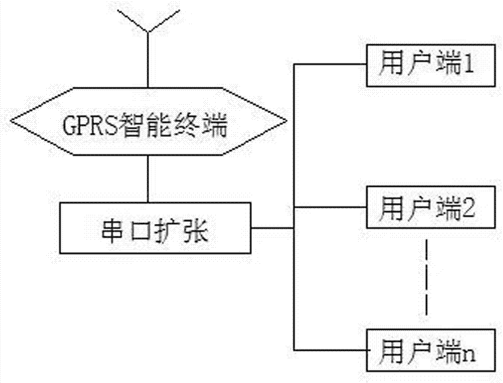
图1是本发明的结构示意图。 Fig. 1 is a structural schematic diagram of the present invention. the
图2是本发明用户端直通式结构示意图。 Fig. 2 is a schematic diagram of the through-type structure of the user terminal in the present invention. the
图3是图本发明用户端直通式的壳体图。 Fig. 3 is a shell diagram of the through-type user terminal of the present invention. the
图4是本发明用户端直通式一次线的接线图。 Fig. 4 is a wiring diagram of the through-type primary line at the user end of the present invention. the
图5是本发明用户端互感式结构示意图。 Fig. 5 is a schematic diagram of the structure of mutual inductance at the user end of the present invention. the
图6是图5的右视图。 FIG. 6 is a right side view of FIG. 5 . the
图7本发明用户端互感式一次线接线图。 Fig. 7 is a wiring diagram of the mutual induction primary line at the user end of the present invention. the
图8是本发明用户端互感式二次线接线图。 Fig. 8 is a wiring diagram of the mutual-inductance secondary line at the user end of the present invention. the
图9是本发明用户端控制器接线图。 Fig. 9 is a wiring diagram of the client controller of the present invention. the
图10是GJ20SG型交流接触器接线图。 Figure 10 is the wiring diagram of the GJ20SG AC contactor. the
图11是合闸控制回路及允许合闸批示灯接线图。 Figure 11 is a wiring diagram of the closing control circuit and the permitting closing indicator light. the
图12是跳闸控制回路及跳闸批示灯接线图。 Figure 12 is a wiring diagram of the trip control circuit and the trip indicator light. the
图13是TM-K1型控制装置接线图。 Figure 13 is a wiring diagram of the TM-K1 control device. the
1、箱体 2、一次导线 3、隔离刀闸 4、无线控制器 5、CJ20S交流接触器 6、零线牌 7、门控开关 8、塑壳断路器 9、控制按钮 10、允许合闸指示灯 
TM-K1型控制装置接线图:一对红线接220V,无方向,一绿线接交流接触器跳闸线圈,无方向,一对黄线接微动门控开关,开门为短接。 TM-K1 type control device wiring diagram: a pair of red wires connected to 220V, no direction, a green wire connected to the trip coil of the AC contactor, no direction, a pair of yellow wires connected to the micro door control switch, and the door is shorted.
具体实施方式 Detailed ways
1、UC-3000C型(直通式)一次线的接线方法 1. Wiring method of UC-3000C (straight-through) primary line
用黄、绿、红、黑四根16m2多股铜线(2),通过进线孔(19)进入箱体(1)内,其中黄、绿、红三根相线接隔离刀闸(3)的上极,隔离刀闸(3)的下极与电能表(15)的进线端子相连,电能表(15)的出线端子与交流接触器(5)的上极相连,交流接触器(5)的下极与塑壳断路器(8)的上极相连,塑壳断路器(8)的下极通过出线孔(22)与用户侧相连。黑色零线与零线铜牌(6)相连,然后再通过出线孔(22)与用户侧相连。电能表(15)零线端子与零线铜牌(6)相连。 Use yellow, green, red, and black four 16m2 multi-strand copper wires (2) to enter the box (1) through the wire inlet hole (19), and the yellow, green, and red phase wires are connected to the isolation switch (3) The upper pole of the isolation switch (3), the lower pole of the isolation switch (3) is connected to the incoming line terminal of the electric energy meter (15), the outgoing line terminal of the electric energy meter (15) is connected to the upper pole of the AC contactor (5), and the AC contactor (5) ) is connected to the upper pole of the molded case circuit breaker (8), and the lower pole of the molded case circuit breaker (8) is connected to the user side through the outlet hole (22). The black neutral wire is connected to the neutral wire copper plate (6), and then connected to the user side through the outlet hole (22). The neutral wire terminal of the electric energy meter (15) is connected with the neutral wire copper plate (6).
2、UC-3000B型(互感式)一次线的接线方法 2. Wiring method of UC-3000B (mutual inductance) primary line
用黄、绿、红、黑四根16m2多股铜线(2),通过进线孔(19)进入箱体(1)内,其中黄、绿、红三根相线接隔离刀闸(3)的上极,隔离刀闸(3)的下极与交流接触器(5)的上极相连,交流接触器(5)的下极通过电流互感器(21)的中心圆孔与塑壳断路器(8)的上极相连,塑壳断路器(8)的下极通过出线孔(22)与用户侧相连。黑色零线与零线铜牌(6)相连,然后再通过出线孔(22)与用户侧相连。 Use yellow, green, red, and black four 16m2 multi-strand copper wires (2) to enter the box (1) through the wire inlet hole (19), and the yellow, green, and red phase wires are connected to the isolation switch (3) The upper pole of the isolation switch (3) is connected to the upper pole of the AC contactor (5), and the lower pole of the AC contactor (5) is connected to the molded case circuit breaker through the center hole of the current transformer (21). (8) is connected to the upper pole, and the lower pole of the molded case circuit breaker (8) is connected to the user side through the outlet hole (22). The black neutral wire is connected to the neutral wire copper plate (6), and then connected to the user side through the outlet hole (22).
Claims (6)
Priority Applications (1)
| Application Number | Priority Date | Filing Date | Title |
|---|---|---|---|
| CN201110414672.3A CN103166312B (en) | 2011-12-13 | 2011-12-13 | Low voltage long distance intelligent residential district motive power prepayment |
Applications Claiming Priority (1)
| Application Number | Priority Date | Filing Date | Title |
|---|---|---|---|
| CN201110414672.3A CN103166312B (en) | 2011-12-13 | 2011-12-13 | Low voltage long distance intelligent residential district motive power prepayment |
Publications (2)
| Publication Number | Publication Date |
|---|---|
| CN103166312A true CN103166312A (en) | 2013-06-19 |
| CN103166312B CN103166312B (en) | 2015-10-28 |
Family
ID=48589147
Family Applications (1)
| Application Number | Title | Priority Date | Filing Date |
|---|---|---|---|
| CN201110414672.3A Expired - Fee Related CN103166312B (en) | 2011-12-13 | 2011-12-13 | Low voltage long distance intelligent residential district motive power prepayment |
Country Status (1)
| Country | Link |
|---|---|
| CN (1) | CN103166312B (en) |
Cited By (3)
| Publication number | Priority date | Publication date | Assignee | Title |
|---|---|---|---|---|
| CN104459253A (en) * | 2014-12-21 | 2015-03-25 | 重庆三峡学院 | Intelligent electric meter based on network |
| CN105405212A (en) * | 2015-10-26 | 2016-03-16 | 国网山东昌乐县供电公司 | Electric charge bookkeeping early warning device |
| CN114113727A (en) * | 2021-10-21 | 2022-03-01 | 广西电网有限责任公司崇左供电局 | High Current Charge Controlled Switching Converter |
Citations (3)
| Publication number | Priority date | Publication date | Assignee | Title |
|---|---|---|---|---|
| CN101854042A (en) * | 2010-04-07 | 2010-10-06 | 辽宁省电力有限公司锦州供电公司 | GPRS network meter intelligent terminal box |
| CN201993838U (en) * | 2011-01-19 | 2011-09-28 | 江西光景电力设备有限公司 | Low-voltage prepayment control cabinet |
| CN202033395U (en) * | 2011-04-25 | 2011-11-09 | 张泽虎 | Multifunctional intelligent high-voltage metering box |
-
2011
- 2011-12-13 CN CN201110414672.3A patent/CN103166312B/en not_active Expired - Fee Related
Patent Citations (3)
| Publication number | Priority date | Publication date | Assignee | Title |
|---|---|---|---|---|
| CN101854042A (en) * | 2010-04-07 | 2010-10-06 | 辽宁省电力有限公司锦州供电公司 | GPRS network meter intelligent terminal box |
| CN201993838U (en) * | 2011-01-19 | 2011-09-28 | 江西光景电力设备有限公司 | Low-voltage prepayment control cabinet |
| CN202033395U (en) * | 2011-04-25 | 2011-11-09 | 张泽虎 | Multifunctional intelligent high-voltage metering box |
Cited By (3)
| Publication number | Priority date | Publication date | Assignee | Title |
|---|---|---|---|---|
| CN104459253A (en) * | 2014-12-21 | 2015-03-25 | 重庆三峡学院 | Intelligent electric meter based on network |
| CN105405212A (en) * | 2015-10-26 | 2016-03-16 | 国网山东昌乐县供电公司 | Electric charge bookkeeping early warning device |
| CN114113727A (en) * | 2021-10-21 | 2022-03-01 | 广西电网有限责任公司崇左供电局 | High Current Charge Controlled Switching Converter |
Also Published As
| Publication number | Publication date |
|---|---|
| CN103166312B (en) | 2015-10-28 |
Similar Documents
| Publication | Publication Date | Title |
|---|---|---|
| CN107472058B (en) | An intelligent charging system for DC charging piles | |
| CN109581047B (en) | Arrearage power failure early warning device, using method and arrearage early warning prompting method | |
| CN104020328A (en) | An anti-theft electric meter box | |
| CN202383770U (en) | Intelligent electric meter fee control device | |
| CN103166312B (en) | Low voltage long distance intelligent residential district motive power prepayment | |
| CN104361685A (en) | Power purchase type intelligent electric meter box | |
| CN201788212U (en) | Box-type power stealing-prevention electric energy metering device | |
| CN204858747U (en) | Long -range combined floodgate system of earth leakage protection circuit breaker is qualified for next round of competitions in platform district | |
| CN206194030U (en) | High pressure prepayment device and system | |
| CN105929213A (en) | Automatic power interruption and delivery apparatus based on three-phase four-wire metering | |
| CN204086340U (en) | A kind of switch external intelligent electric energy meter stops repeating installation | |
| CN203849804U (en) | Intelligent prepayment control device | |
| CN205644195U (en) | Control circuit of high pressure prepayment switch electricity behaviour mechanism | |
| CN209044774U (en) | A kind of prepaid low-voltage broken circuit control device | |
| CN206876737U (en) | Acquiring electric energy information and control system terminal | |
| CN101026660A (en) | Mobile phone prepaid fee power management terminal | |
| CN207360105U (en) | A kind of direct-current charging post intelligent charging system | |
| CN207164110U (en) | A kind of remote bill control is sent a telegram in reply batch meter automatically | |
| CN204243898U (en) | A kind of circuit breaker with distant control function | |
| CN214504517U (en) | User prepayment tripping circuit protection box | |
| CN104794821A (en) | Water-electricity-coal gas integrated charging control system | |
| CN110600338A (en) | Low-voltage intelligent charge control switch | |
| CN203895132U (en) | The meter box that can still play the function of preventing electricity theft during power failure | |
| CN205029433U (en) | Long -range separating brake controlling means and system | |
| CN115986904A (en) | A protection measurement and control system for standby automatic switching |
Legal Events
| Date | Code | Title | Description |
|---|---|---|---|
| C06 | Publication | ||
| PB01 | Publication | ||
| C10 | Entry into substantive examination | ||
| SE01 | Entry into force of request for substantive examination | ||
| C14 | Grant of patent or utility model | ||
| C41 | Transfer of patent application or patent right or utility model | ||
| CB02 | Change of applicant information |
Address after: 455000 north section of Zhongzhou Road, Anyang, Henan Applicant after: STATE GRID HENAN ELECTRIC POWER COMPANY ANYANG POWER SUPPLY Co. Address before: 455000 north section of Zhongzhou Road, Anyang, Henan Applicant before: ANYANG POWER SUPPLY COMPANY OF HENAN ELECTRIC POWER Co. |
|
| CB03 | Change of inventor or designer information |
Inventor after: Qiao Chongge Inventor after: Wang Xin Inventor after: Wang Liye Inventor after: Guo Xinhai Inventor after: Wang Xiaolei Inventor after: Chang Ruiqiang Inventor before: Wang Xiumin |
|
| COR | Change of bibliographic data | ||
| GR01 | Patent grant | ||
| TA01 | Transfer of patent application right |
Effective date of registration: 20150923 Address after: 100031 Xicheng District West Chang'an Avenue, No. 86, Beijing Applicant after: State Grid Corporation of China Applicant after: STATE GRID HENAN ELECTRIC POWER COMPANY ANYANG POWER SUPPLY Co. Address before: 455000 north section of Zhongzhou Road, Anyang, Henan Applicant before: STATE GRID HENAN ELECTRIC POWER COMPANY ANYANG POWER SUPPLY Co. |
|
| CF01 | Termination of patent right due to non-payment of annual fee | ||
| CF01 | Termination of patent right due to non-payment of annual fee |
Granted publication date: 20151028 |