CN103180010A - Multi-electrode neurostimulation device - Google Patents
Multi-electrode neurostimulation device Download PDFInfo
- Publication number
- CN103180010A CN103180010A CN2011800520208A CN201180052020A CN103180010A CN 103180010 A CN103180010 A CN 103180010A CN 2011800520208 A CN2011800520208 A CN 2011800520208A CN 201180052020 A CN201180052020 A CN 201180052020A CN 103180010 A CN103180010 A CN 103180010A
- Authority
- CN
- China
- Prior art keywords
- stimulation
- orientation
- electric field
- field gradient
- profile
- Prior art date
- Legal status (The legal status is an assumption and is not a legal conclusion. Google has not performed a legal analysis and makes no representation as to the accuracy of the status listed.)
- Pending
Links
Images
Classifications
-
- A—HUMAN NECESSITIES
- A61—MEDICAL OR VETERINARY SCIENCE; HYGIENE
- A61N—ELECTROTHERAPY; MAGNETOTHERAPY; RADIATION THERAPY; ULTRASOUND THERAPY
- A61N1/00—Electrotherapy; Circuits therefor
- A61N1/02—Details
- A61N1/04—Electrodes
- A61N1/05—Electrodes for implantation or insertion into the body, e.g. heart electrode
- A61N1/0526—Head electrodes
- A61N1/0529—Electrodes for brain stimulation
- A61N1/0531—Brain cortex electrodes
-
- A—HUMAN NECESSITIES
- A61—MEDICAL OR VETERINARY SCIENCE; HYGIENE
- A61N—ELECTROTHERAPY; MAGNETOTHERAPY; RADIATION THERAPY; ULTRASOUND THERAPY
- A61N1/00—Electrotherapy; Circuits therefor
- A61N1/02—Details
- A61N1/04—Electrodes
- A61N1/05—Electrodes for implantation or insertion into the body, e.g. heart electrode
- A61N1/0551—Spinal or peripheral nerve electrodes
- A61N1/0553—Paddle shaped electrodes, e.g. for laminotomy
-
- A—HUMAN NECESSITIES
- A61—MEDICAL OR VETERINARY SCIENCE; HYGIENE
- A61N—ELECTROTHERAPY; MAGNETOTHERAPY; RADIATION THERAPY; ULTRASOUND THERAPY
- A61N1/00—Electrotherapy; Circuits therefor
- A61N1/18—Applying electric currents by contact electrodes
- A61N1/32—Applying electric currents by contact electrodes alternating or intermittent currents
- A61N1/36—Applying electric currents by contact electrodes alternating or intermittent currents for stimulation
- A61N1/3605—Implantable neurostimulators for stimulating central or peripheral nerve system
- A61N1/36128—Control systems
- A61N1/36135—Control systems using physiological parameters
- A61N1/36139—Control systems using physiological parameters with automatic adjustment
-
- A—HUMAN NECESSITIES
- A61—MEDICAL OR VETERINARY SCIENCE; HYGIENE
- A61N—ELECTROTHERAPY; MAGNETOTHERAPY; RADIATION THERAPY; ULTRASOUND THERAPY
- A61N1/00—Electrotherapy; Circuits therefor
- A61N1/18—Applying electric currents by contact electrodes
- A61N1/32—Applying electric currents by contact electrodes alternating or intermittent currents
- A61N1/36—Applying electric currents by contact electrodes alternating or intermittent currents for stimulation
- A61N1/3605—Implantable neurostimulators for stimulating central or peripheral nerve system
- A61N1/36128—Control systems
- A61N1/36146—Control systems specified by the stimulation parameters
- A61N1/3615—Intensity
- A61N1/3616—Voltage density or current density
-
- A—HUMAN NECESSITIES
- A61—MEDICAL OR VETERINARY SCIENCE; HYGIENE
- A61N—ELECTROTHERAPY; MAGNETOTHERAPY; RADIATION THERAPY; ULTRASOUND THERAPY
- A61N1/00—Electrotherapy; Circuits therefor
- A61N1/18—Applying electric currents by contact electrodes
- A61N1/32—Applying electric currents by contact electrodes alternating or intermittent currents
- A61N1/36—Applying electric currents by contact electrodes alternating or intermittent currents for stimulation
- A61N1/3605—Implantable neurostimulators for stimulating central or peripheral nerve system
- A61N1/36128—Control systems
- A61N1/36146—Control systems specified by the stimulation parameters
- A61N1/36182—Direction of the electrical field, e.g. with sleeve around stimulating electrode
- A61N1/36185—Selection of the electrode configuration
Landscapes
- Health & Medical Sciences (AREA)
- Neurology (AREA)
- Neurosurgery (AREA)
- Life Sciences & Earth Sciences (AREA)
- General Health & Medical Sciences (AREA)
- Animal Behavior & Ethology (AREA)
- Engineering & Computer Science (AREA)
- Biomedical Technology (AREA)
- Nuclear Medicine, Radiotherapy & Molecular Imaging (AREA)
- Radiology & Medical Imaging (AREA)
- Veterinary Medicine (AREA)
- Public Health (AREA)
- Heart & Thoracic Surgery (AREA)
- Cardiology (AREA)
- Psychology (AREA)
- Biophysics (AREA)
- Physiology (AREA)
- Orthopedic Medicine & Surgery (AREA)
- Electrotherapy Devices (AREA)
Abstract
A neurostimulation device is provided comprising an input, a neurostimulation probe, a stimulation unit and a distribution calculation module. At the input stimulation data is received comprising information relating to a stimulation preferability and an orientation of at least one fiber bundle. The neurostimulation probe comprises an array of stimulation electrodes which are coupled to the stimulation unit. The stimulation unit, in accordance with a specified current distribution, provides currents to the respective stimulation electrodes for generating an electric field gradient. The distribution calculation module is coupled to the input and the stimulation unit for based on the stimulation data determining a preferred position and orientation for the electric field gradient, and based on the preferred position and orientation for the electric field gradient, calculating the specified current distribution.
Description
Technical field
The present invention relates to a kind of nerve stimulation apparatus, it comprises: be used for receiving the input of stimulus data, this stimulus data comprises the information relevant with orientation to the preferred property of the stimulation of at least one fibre bundle; The nerve stimulation probe, it has the array of stimulating electrode; Stimulating unit, it is coupled to stimulating electrode, with the CURRENT DISTRIBUTION according to appointment, electric current is offered corresponding stimulating electrode, to generate electric field; And the distribution computing module, it is coupled to input and stimulating unit, with the optimum position of determining electric field based on stimulus data and the CURRENT DISTRIBUTION of calculating appointment based on the optimum position of electric field.
Background technology
Be used for providing the system of nerve stimulation to be used to the treatment imbalance via the probe of implanting, such as chronic pain, Parkinson's disease, tremble and myodystonia.Nerve stimulation is used for stimulating the nervous tissue of brain, spinal cord and peripheral nerve.Below the nerve stimulation of cerebral tissue will be discussed.Yet system and a method according to the invention can also be for the nerve stimulation of for example spinal cord and peripheral nerve.Probe is implanted in brain in operating mode, near the cerebral tissue that will stimulate.When using nerve stimulation, importantly, the tissue that needs are stimulated stimulates and avoids near to organizing other stimulation.Therefore, the correct placement of probe is the important step in successful neural stimulation therapy.In the known system of the implantation of planning probe, use the imaging technique such as nuclear magnetic resonance (MRI) to come visual target area.The surgeon attempts locating the structure that needs stimulation, and attempts the surgical operation plan that definition is used for probe is implanted to the structure of identifying.
Attempt to stimulate the known way of correct tissue regions to be: implant and have the probe of a plurality of electrodes, and the subset of only selecting these electrodes to be only to stimulate specific tissue regions.For example, in US patent application US 2008/0215125 and US 2010/0030298, this point has been described.These US applications have been described near the regional implanted probe with a plurality of electrodes of paying close attention to.Electric charge is supplied to the subset of these electrodes, optionally to stimulate specific tissue regions.In addition, in US patent 7,442,183, activate the subset of a plurality of electrodes, with electric field leading to the target area.At US 7,442, notice in 183, make the accurate probe location with respect to object construction become so crucial to the selective activation of the subset of electrode.
Although the use of electrod-array makes it possible to the 3D Electric Field Distribution is guided to specific tissue regions, the four corner of the 3D stimulus modelity that can create still depends on exact position and the orientation of probe.For optimum treatment dispensing option and tuning motility thereof, should arrange in treatment plan optimum leading location in the stage.
Goal of the invention
The purpose of this invention is to provide a kind of nerve stimulation apparatus, it allows the calibration (targeting) more accurately to specific neuromechanism, to improve neural stimulation therapy.
Summary of the invention
According to a first aspect of the invention, this purpose is by providing a kind of nerve stimulation apparatus to realize, described nerve stimulation apparatus comprises input, nerve stimulation probe, stimulating unit and distribution computing module.At described input end, receive stimulus data, described stimulus data comprises the information relevant with orientation to the preferred property of the stimulation of at least one fibre bundle.Described nerve stimulation probe comprises the array of the stimulating electrode that is coupled to described stimulating unit.Described stimulating unit offers corresponding stimulating electrode according to the CURRENT DISTRIBUTION of appointment with electric current, to generate electric-force gradient.Described distribution computing module is coupled to described input and described stimulating unit, determining preferred position and the orientation of described electric-force gradient based on described stimulus data, and based on preferred position and the directed CURRENT DISTRIBUTION of calculating appointment of described electric-force gradient.
Nerve stimulation apparatus according to the present invention has not only been considered the position of object construction when applying stimulus field, but also has considered the orientation of object construction.Especially for fibre bundle, be the key factor that determines the effectiveness of neural stimulation therapy with respect to the orientation of the electricity irritation field of the orientation of fibre bundle.Although the nerve stimulation apparatus of prior art is only attempted stimulating brain in specific target location, the direction of the direction of also having considered target fibers according to nerve stimulation apparatus of the present invention and the gradient of the electricity irritation field that generates.
Have been found that when electric-force gradient and target fibers Shu Pinghang or almost parallel, the most easily realize the activation to certain fiber.Utilize and non-target fibers Shu Chuizhi or substantially vertical electric-force gradient, the most easily realize the selectivity of fiber is not activated.By using up-to-date imaging technique (such as diffusion tensor (DTI)), can identify independent fibre bundle and position thereof and orientation.The distribution computing module is identified for position and the orientation of the optimum electric-force gradient of neural stimulation therapy with this information.This optimum electric-force gradient can cause the maximal stimulus to target fibers, but also can provide the target that needs are stimulated stimulate and avoid the balance between preferably inirritative structure stimulates.When the known preferred electric-force gradient, calculate the distribution on the electrode of stimulating current in array, to obtain optimum electric-force gradient.Then, thus obtained stimulating current distribution is offered stimulating unit.
Respective electrode in the stimulating unit pair array applies the electric current that calculates, to obtain optimum electric-force gradient.Therefore, nerve stimulation apparatus according to the present invention makes and can generate the electricity irritation field with parallel with the fibre bundle that should stimulate (roughly) and/or vertical with the fibre bundle that should not stimulate (roughly) field gradient.
, the orientation of target fibers and relative position and the orientation of electrod-array are compared when stimulating when the section of selecting specific fibre bundle for example or fibre bundle.Then, this part of target fibers bundle can be projected to stimulates on array, thereby obtains directional vector.In the embodiment according to nerve stimulation apparatus of the present invention, then, activate three groups of electrodes and have the electric field of the gradient parallel with this directional vector with generation.In this example, the CURRENT DISTRIBUTION of appointment is three polar stimulation scattergrams (profile).First group of electrode with first polarity is positioned at the center on directional vector.Select second and the 3rd group of electrode at the opposite side place of first group and along directional vector.Second and the 3rd group has the polarity opposite with first group.Can offer second and the 3rd group of electrode by the electric current that will equate and come the balance total current, first group of electrode receives the double electric current with opposite polarity.
Stimulus data can also comprise the information relevant from the different sections fibre diameters of locating of fibre bundle.When fibre bundle hour, easier with static focusing on fibre bundle, and organize near can attentively stimulating other.In addition, the required electric field intensity of effective stimulus treatment is less.When using this diameter data, can select stimulating electrode, generate electric-force gradient with near the narrow section of fibre bundle or the proper narrow section place at fibre bundle.
Stimulus data can also comprise and the information relevant with respect to the fiber alignment variation of fibre bundle length.For example, when attempt stimulating a plurality of fibre bundle or when the stimulation attempting avoiding near fibre bundle, can stimulate better the sections of the different orientations of fibre bundle, rather than the narrowest section or with immediate section of stimulating electrode.
Therefore, in the preferred embodiment according to nerve stimulation apparatus of the present invention, specified the CURRENT DISTRIBUTION that causes the optimal balance between maximized curative effect and minimized adverse side effect.This optimal current distribute diameter and diameter and the orientation directed and that preferably will avoid one or more fibre bundles of stimulating of the different sections of having considered one or more target fibers bundles.
A kind of method of CURRENT DISTRIBUTION of array computation appointment of the stimulating electrode for nerve stimulation apparatus is provided according to a second aspect of the invention.Said method comprising the steps of: receive stimulus data, described stimulus data comprises the information relevant with orientation to the preferred property of the stimulation of at least one fibre bundle; Determine preferred position and the orientation of the electric-force gradient that the array of stimulating electrode will generate based on described stimulus data; And based on preferred position and the orientation of described electric-force gradient, calculate the CURRENT DISTRIBUTION of appointment.Then, can apply to stimulating electrode the CURRENT DISTRIBUTION of appointment, with the generation electric-force gradient, and provide neural stimulation therapy thereupon.
According to a further aspect in the invention, provide a kind of computer program, be used for making processor to carry out said method.These and other aspects of the present invention are apparent from embodiment described below, and illustrated with reference to embodiment described below.
Description of drawings
In the accompanying drawings:
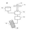
Fig. 1 schematically shows according to nerve stimulation apparatus of the present invention,
Fig. 2 shows according to the present invention can the how to confirm CURRENT DISTRIBUTION, and
Fig. 3 shows the flow chart of the method according to this invention.
The specific embodiment
Fig. 1 schematically shows according to nerve stimulation apparatus 10 of the present invention.Nerve stimulation apparatus 10 comprises the nerve stimulation probe 12 of the array with stimulating electrode 20.When in the brain that probe 20 is implanted to the patient, stimulating electrode 20 can be by generating near the nervous tissue of electric field neural stimulation therapy is offered.Stimulating unit 13 offers electrode 20 with electric current, to generate electric field.By different electric currents being sent to selected electrode 20, can make electric field be targeted at particular organization's location of close probe 12.According to the present invention, stimulating module 13 receives the CURRENT DISTRIBUTION of appointment from distribution computing module 14.The CURRENT DISTRIBUTION of appointment has been specified and should have been applied what electric current to which electrode 20.Calculating to the CURRENT DISTRIBUTION of appointment is based on data 21, and data 21 are described the fibre bundle that should or should not be stimulated, and, hereinafter with reference to Fig. 2, calculating to the CURRENT DISTRIBUTION of appointment is described.The required data 21 of CURRENT DISTRIBUTION of appointment are calculated in input 11 places reception at equipment.Can receive this data 21 by the wired and/or radio communication with the system that is used for the plan neural stimulation therapy.The data that receive can be stored in the memorizer 15 of equipment 10, so that can use equipment 10 when planning system is unavailable.
Therefore, in the preferred embodiment of nerve stimulation apparatus 10 according to the present invention, computing module 14 is specified the CURRENT DISTRIBUTION that causes the optimal balance between maximized curative effect and minimized adverse side effect.This optimal current distribute diameter and diameter and the orientation directed and that preferably will avoid one or more fibre bundles of stimulating of the different sections of having considered one or more target fibers bundles.
Fig. 2 shows can the how to confirm CURRENT DISTRIBUTION according to the present invention.Input data 21 have been described position and the orientation that is selected with at least one fibre bundle 21 that stimulates.In addition, input data 21 can comprise and near fibre bundle 22,23,24 relevant information.Below, we suppose: near fibre bundle 21 implantable probes 12, and (by computing module 14 or by outside planning system) determined and will drawn this fibre bundle 21 of section place's stimulation of fiber alignment vector 25.
For example, can followingly determine like that to cause the optimal current of optimum electric-force gradient to distribute:
-at first, fiber alignment vector 25 is projected on the array of stimulating electrode 20.
-then, computing module 24 determines should apply which electric current to which electrode 20 in order to obtain the electric-force gradient parallel with the vector 26 of institute projection.In this example, select one group of electrode 31 of central authorities.
-current value is divided the electrode 31 of tasking in this center stack.
-at the opposite side of this center stack electrode 31 and along the direction of the vector 26 of institute's projection, select second and the 3rd group of electrode 32,33.
-also determine second and the 3rd group of electrode 32,33 current value.Be used for the current value of second and the 3rd group 32,33 and have opposite polarity polarity with the current value that is used for center stack 31.As a result of, the electric-force gradient that produces will be directed along fiber alignment vector 25.Can come the balance total current by the current value that center stack electrode 31 is applied as follows: except polarity, the current value that center stack electrode 31 is applied is the twice to second and the 3rd group of current value that electrode 32,33 applies.
Should be noted that other CURRENT DISTRIBUTION also can cause suitably directed electric-force gradient.In the example scenario that provides, fiber alignment vector 25 is straight lines, and electrode 20 is provided on smooth surface.Yet in a similar fashion, computing module 14 can calculate for the CURRENT DISTRIBUTION that stimulates curved fiber bundle section.In addition, the array of stimulating electrode needs not to be smooth surface.
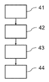
Fig. 3 shows the flow chart of the method according to this invention.The step of the method can be carried out by the distribution computing module 14 of the nerve stimulation apparatus 10 of Fig. 1.The method starts from data receiver step 41, and the input 11 that data receiver step 41 is used for slave unit 10 receives stimulus data 21.When data 21 are sent to equipment 10, can directly the data that receive be passed to distribution computing module 14 and be processed by distribution computing module 14.Replacedly, data 21 temporarily are stored in memorizer 15 for follow-up use.
In directed determining step 42, determine preferred position and the orientation of the electric-force gradient that the array of stimulating electrode 20 will generate.Based on the data that receive, determine position and the orientation of electric-force gradient in data receiver step 41.In the above, described for the illustrative methods of doing like this with reference to Fig. 2.In distribution calculation procedure 43, calculate the determined position and the directed CURRENT DISTRIBUTION that cause electric-force gradient.Then, in stimulation step 44, stimulating unit 13 can apply the CURRENT DISTRIBUTION that calculates to corresponding stimulating electrode 20.
To recognize, the present invention also extends to and is suitable for implementing on computer program of the present invention, particularly carrier or the computer program in carrier.This program can be source code, object code, code intermediate source and such as the form of the object code of the form of part compiling, or any other form that is suitable for using in the embodiment of the method according to this invention.Also will recognize, this program can have many different architecture designs.For example, the program code of realizing the function of the method according to this invention or system can be subdivided into one or more subroutines.The many different modes that are used for function is distributed in the middle of these subroutines for a person skilled in the art will be apparent.Subroutine can be stored in together in an executable file to form self-contained program.This executable file can comprise computer executable instructions, for example processor instruction and/or interpreter instruction (for example, Java interpreter instruction).Replacedly, one or more or all subroutines can be stored at least one external libraries file and with statically or dynamically when operation (for example) link of mastery routine.Mastery routine comprise at least one subroutine at least one call.In addition, subroutine can comprise the function call to each other.The embodiment relevant to computer program comprise with the method for setting forth in the treatment step of at least one method in each corresponding computer executable instructions.These instructions can be subdivided into subroutine and/or be stored in can be by in one or more files of static state or dynamic link.Another embodiment relevant to computer program comprise with the system that sets forth and/or product at least one device in each corresponding computer executable instructions.These instructions can be subdivided into subroutine and/or be stored in can be by in one or more files of static state or dynamic link.
The carrier of computer program can be can performing a programme any entity or equipment.For example, carrier can comprise storage medium, such as ROM(for example, and CD ROM or quasiconductor ROM) or magnetic recording media (for example, floppy disk or hard disk).In addition, but carrier can be can be via cable or optical cable or the transport vehicle (such as electricity or optical signal) that transmits by radio or other devices.When realizing program in sort signal, carrier can be made of this cable or other equipment or device.Replacedly, carrier can be the integrated circuit that wherein embeds program, and this integrated circuit is suitable for carrying out correlation technique or uses in the execution of correlation technique.
Should be noted that above-described embodiment to illustrate and unrestricted the present invention, and those skilled in the art can design many alternative embodiments in the situation that do not break away from the scope of claims.In the claims, any reference marker that is placed between bracket should not be construed as restriction claim.Verb " is comprised " and the use of displacement is not got rid of have element or the element step or the step of stating in claim.Article " one " before element or " one " do not get rid of and have a plurality of this elements.Hardware that can be by comprising some different elements and realize the present invention by the computer of suitable programming.In having enumerated the equipment claim of a plurality of devices, several in these devices can be realized by same hardware.The minimum fact of the certain means of record does not indicate the combination of these means can not be used for benefiting in mutually different dependent claims.
Claims (9)
Applications Claiming Priority (3)
| Application Number | Priority Date | Filing Date | Title |
|---|---|---|---|
| EP10189489.7 | 2010-10-29 | ||
| EP10189489 | 2010-10-29 | ||
| PCT/EP2011/069090 WO2012056039A1 (en) | 2010-10-29 | 2011-10-31 | Multi-electrode neurostimulation device |
Publications (1)
| Publication Number | Publication Date |
|---|---|
| CN103180010A true CN103180010A (en) | 2013-06-26 |
Family
ID=44910199
Family Applications (1)
| Application Number | Title | Priority Date | Filing Date |
|---|---|---|---|
| CN2011800520208A Pending CN103180010A (en) | 2010-10-29 | 2011-10-31 | Multi-electrode neurostimulation device |
Country Status (5)
| Country | Link |
|---|---|
| US (2) | US9020604B2 (en) |
| EP (1) | EP2632537B1 (en) |
| CN (1) | CN103180010A (en) |
| BR (1) | BR112013010032A2 (en) |
| WO (1) | WO2012056039A1 (en) |
Cited By (2)
| Publication number | Priority date | Publication date | Assignee | Title |
|---|---|---|---|---|
| CN104888349A (en) * | 2014-12-21 | 2015-09-09 | 徐志强 | Method and device for carrying out brain activation on dead or brain-dead cerebrum |
| CN106537940A (en) * | 2014-06-03 | 2017-03-22 | 耳蜗有限公司 | Fitting method using channels |
Families Citing this family (23)
| Publication number | Priority date | Publication date | Assignee | Title |
|---|---|---|---|---|
| EP2644227B1 (en) | 2008-07-30 | 2016-12-28 | Ecole Polytechnique Fédérale de Lausanne | Apparatus for optimized stimulation of a neurological target |
| CA2743575C (en) | 2008-11-12 | 2017-01-31 | Ecole Polytechnique Federale De Lausanne | Microfabricated neurostimulation device |
| CA2782710C (en) | 2009-12-01 | 2019-01-22 | Ecole Polytechnique Federale De Lausanne | Microfabricated neurostimulation device and methods of making and using the same |
| EP2552536B1 (en) | 2010-04-01 | 2016-06-08 | Ecole Polytechnique Fédérale de Lausanne (EPFL) | Device for interacting with neurological tissue |
| CN103180010A (en) * | 2010-10-29 | 2013-06-26 | 沙皮恩斯脑部刺激控制有限公司 | Multi-electrode neurostimulation device |
| WO2013173551A1 (en) | 2012-05-16 | 2013-11-21 | University Of Utah Research Foundation | Charge steering high density electrode array |
| WO2014117208A1 (en) | 2013-01-29 | 2014-08-07 | National Ict Australia Limited | Neuroprosthetic stimulation |
| US8874233B2 (en) | 2013-03-05 | 2014-10-28 | The Charles Stark Draper Laboratory, Inc. | Distributed neuro-modulation system with auxiliary stimulation-recording control units |
| EP2810689A1 (en) * | 2013-06-06 | 2014-12-10 | Sapiens Steering Brain Stimulation B.V. | A system for planning and/or providing a therapy for neural applications |
| WO2014161789A1 (en) | 2013-04-05 | 2014-10-09 | Sapiens Steering Brain Stimulation B.V. | A system for planning and/or providing a therapy for neural applications |
| WO2015173787A1 (en) | 2014-05-16 | 2015-11-19 | Aleva Neurotherapeutics Sa | Device for interacting with neurological tissue and methods of making and using the same |
| US11311718B2 (en) | 2014-05-16 | 2022-04-26 | Aleva Neurotherapeutics Sa | Device for interacting with neurological tissue and methods of making and using the same |
| US9474894B2 (en) | 2014-08-27 | 2016-10-25 | Aleva Neurotherapeutics | Deep brain stimulation lead |
| US9403011B2 (en) | 2014-08-27 | 2016-08-02 | Aleva Neurotherapeutics | Leadless neurostimulator |
| US10426362B2 (en) | 2014-11-10 | 2019-10-01 | The Board Of Trustees Of The Leland Stanford Junior University | Deep-brain probe and method for recording and stimulating brain activity |
| US9364659B1 (en) | 2015-04-27 | 2016-06-14 | Dantam K. Rao | Smart lead for deep brain stimulation |
| WO2017134587A1 (en) | 2016-02-02 | 2017-08-10 | Aleva Neurotherapeutics, Sa | Treatment of autoimmune diseases with deep brain stimulation |
| WO2017180482A1 (en) | 2016-04-11 | 2017-10-19 | Paradromics, Inc. | Neural-interface probe and methods of packaging the same |
| US10300285B2 (en) | 2017-01-05 | 2019-05-28 | Medtronic Bakken Research Center B.V. | Impedance-based allocation of electrical stimulation to electrode clusters |
| US10912941B2 (en) | 2017-01-05 | 2021-02-09 | Regents Of The University Of Minnesota | System and method for feedback-driven neuromodulation |
| WO2018183967A1 (en) | 2017-03-30 | 2018-10-04 | Paradromics, Inc. | Patterned microwire bundles and methods of producing the same |
| US10702692B2 (en) | 2018-03-02 | 2020-07-07 | Aleva Neurotherapeutics | Neurostimulation device |
| US12171995B1 (en) | 2021-10-07 | 2024-12-24 | Paradromics, Inc. | Methods for improved biocompatibility for human implanted medical devices |
Citations (4)
| Publication number | Priority date | Publication date | Assignee | Title |
|---|---|---|---|---|
| US20020038095A1 (en) * | 1999-12-17 | 2002-03-28 | Tucker Don M. | Method for localizing electrical activity in the body |
| US20080114579A1 (en) * | 2004-07-07 | 2008-05-15 | The Cleveland Clinic Foundation | Brain Stimulation models, systems, devices, and methods |
| WO2010065888A2 (en) * | 2008-12-04 | 2010-06-10 | The Cleveland Clinic Foundation | System and method to define target volume for stimulation in brain |
| WO2010120823A2 (en) * | 2009-04-13 | 2010-10-21 | Research Foundation Of The City University Of New York | Neurocranial electrostimulation models, systems, devices and methods |
Family Cites Families (13)
| Publication number | Priority date | Publication date | Assignee | Title |
|---|---|---|---|---|
| US4019518A (en) * | 1975-08-11 | 1977-04-26 | Medtronic, Inc. | Electrical stimulation system |
| EP1779890B8 (en) * | 1997-07-16 | 2009-07-08 | Metacure Limited | Smooth muscle controller |
| US6353762B1 (en) | 1999-04-30 | 2002-03-05 | Medtronic, Inc. | Techniques for selective activation of neurons in the brain, spinal cord parenchyma or peripheral nerve |
| US7881805B2 (en) * | 2002-02-04 | 2011-02-01 | Boston Scientific Neuromodulation Corporation | Method for optimizing search for spinal cord stimulation parameter settings |
| US7930037B2 (en) * | 2003-09-30 | 2011-04-19 | Medtronic, Inc. | Field steerable electrical stimulation paddle, lead system, and medical device incorporating the same |
| US9026228B2 (en) | 2004-10-21 | 2015-05-05 | Medtronic, Inc. | Transverse tripole neurostimulation lead, system and method |
| ES2699474T3 (en) | 2006-08-07 | 2019-02-11 | Alpha Omega Neuro Tech Ltd | Brain electrodes |
| EP2069003B1 (en) | 2006-09-26 | 2014-11-12 | Sapiens Steering Brain Stimulation B.V. | Tissue stimulation apparatus |
| US8612019B2 (en) * | 2007-05-23 | 2013-12-17 | Boston Scientific Neuromodulation Corporation | Coupled monopolar and multipolar pulsing for conditioning and stimulation |
| US8326433B2 (en) * | 2008-05-15 | 2012-12-04 | Intelect Medical, Inc. | Clinician programmer system and method for calculating volumes of activation for monopolar and bipolar electrode configurations |
| US8452414B2 (en) * | 2009-09-29 | 2013-05-28 | Medtronic, Inc. | Steering stimulation current by employing steering current |
| US8239038B2 (en) * | 2010-10-14 | 2012-08-07 | Wolf Ii Erich W | Apparatus and method using near infrared reflectometry to reduce the effect of positional changes during spinal cord stimulation |
| CN103180010A (en) * | 2010-10-29 | 2013-06-26 | 沙皮恩斯脑部刺激控制有限公司 | Multi-electrode neurostimulation device |
-
2011
- 2011-10-31 CN CN2011800520208A patent/CN103180010A/en active Pending
- 2011-10-31 US US13/285,084 patent/US9020604B2/en active Active
- 2011-10-31 BR BR112013010032A patent/BR112013010032A2/en not_active IP Right Cessation
- 2011-10-31 WO PCT/EP2011/069090 patent/WO2012056039A1/en not_active Ceased
- 2011-10-31 EP EP11779379.4A patent/EP2632537B1/en active Active
-
2015
- 2015-04-24 US US14/696,136 patent/US9572987B2/en active Active
Patent Citations (4)
| Publication number | Priority date | Publication date | Assignee | Title |
|---|---|---|---|---|
| US20020038095A1 (en) * | 1999-12-17 | 2002-03-28 | Tucker Don M. | Method for localizing electrical activity in the body |
| US20080114579A1 (en) * | 2004-07-07 | 2008-05-15 | The Cleveland Clinic Foundation | Brain Stimulation models, systems, devices, and methods |
| WO2010065888A2 (en) * | 2008-12-04 | 2010-06-10 | The Cleveland Clinic Foundation | System and method to define target volume for stimulation in brain |
| WO2010120823A2 (en) * | 2009-04-13 | 2010-10-21 | Research Foundation Of The City University Of New York | Neurocranial electrostimulation models, systems, devices and methods |
Cited By (3)
| Publication number | Priority date | Publication date | Assignee | Title |
|---|---|---|---|---|
| CN106537940A (en) * | 2014-06-03 | 2017-03-22 | 耳蜗有限公司 | Fitting method using channels |
| CN104888349A (en) * | 2014-12-21 | 2015-09-09 | 徐志强 | Method and device for carrying out brain activation on dead or brain-dead cerebrum |
| CN104888349B (en) * | 2014-12-21 | 2021-08-20 | 徐志强 | Device for brain activation |
Also Published As
| Publication number | Publication date |
|---|---|
| EP2632537B1 (en) | 2016-12-07 |
| BR112013010032A2 (en) | 2016-08-02 |
| WO2012056039A1 (en) | 2012-05-03 |
| US20120109262A1 (en) | 2012-05-03 |
| US20150224316A1 (en) | 2015-08-13 |
| US9572987B2 (en) | 2017-02-21 |
| EP2632537A1 (en) | 2013-09-04 |
| US9020604B2 (en) | 2015-04-28 |
Similar Documents
| Publication | Publication Date | Title |
|---|---|---|
| CN103180010A (en) | Multi-electrode neurostimulation device | |
| US8498709B2 (en) | Planning system for neurostimulation therapy | |
| US7471974B2 (en) | Method for planning stimulation of hyper/hypometabolic cortical areas | |
| RU2463088C2 (en) | Method and device for tissue stimulation | |
| US10806929B2 (en) | Systems and method for deep brain stimulation therapy | |
| JP6352416B2 (en) | System, method, and visualization tool for stimulation and sensing of the nervous system using a system level interaction model | |
| US10576296B2 (en) | Navigated transcranial magnetic stimulation planning using a structural effectiveness index | |
| US9662492B1 (en) | Method for transcranial neurostimulation | |
| US11484714B2 (en) | Cochlear implant localization system | |
| Coenen et al. | Postoperative neuroimaging analysis of DRT deep brain stimulation revision surgery for complicated essential tremor | |
| JP2013519418A (en) | Method and system for determining settings in deep brain stimulation therapy | |
| EP3666183B1 (en) | Bioimpedance measurement method and apparatus with electrical stimulation performance | |
| US20190240488A1 (en) | Cochlear Implant Localization System | |
| US20140364679A1 (en) | Multi-Coil Transcranial Magnetic Stimulation | |
| Vila‐Rodriguez et al. | Individualized functional targeting for rTMS: A powerful idea whose time has come? | |
| CN117860376A (en) | Neurosurgery Planning System | |
| US10751132B2 (en) | Cochlear implant localization system | |
| EP3192559B1 (en) | Guiding tube for stimulation leads | |
| JP2021512661A (en) | Cochlear implant positioning system | |
| US11878170B2 (en) | Apparatus and method for closed-loop model-based electrical brain stimulation | |
| US20210402200A1 (en) | Method and apparatus for modulation of tracts in nervous tissue | |
| Herr et al. | Leveraging Neuroscience Imaging and Electrophysiological Assessments to Decode Neuron-Glioma Interactions | |
| von Campe et al. | The use of nrTMS data for tractography of language networks | |
| KR20240139184A (en) | Apparatus, method and recording medium for controlling cognitive processing speed through non-invasive brain stimulation | |
| JPWO2023043786A5 (en) |
Legal Events
| Date | Code | Title | Description |
|---|---|---|---|
| C06 | Publication | ||
| PB01 | Publication | ||
| C10 | Entry into substantive examination | ||
| SE01 | Entry into force of request for substantive examination | ||
| C02 | Deemed withdrawal of patent application after publication (patent law 2001) | ||
| WD01 | Invention patent application deemed withdrawn after publication |
Application publication date: 20130626 |