CN103192995A - Rotary piston type spring ejector - Google Patents
Rotary piston type spring ejector Download PDFInfo
- Publication number
- CN103192995A CN103192995A CN2012105873679A CN201210587367A CN103192995A CN 103192995 A CN103192995 A CN 103192995A CN 2012105873679 A CN2012105873679 A CN 2012105873679A CN 201210587367 A CN201210587367 A CN 201210587367A CN 103192995 A CN103192995 A CN 103192995A
- Authority
- CN
- China
- Prior art keywords
- ejector
- aircraft
- gear
- shell
- main shaft
- Prior art date
- Legal status (The legal status is an assumption and is not a legal conclusion. Google has not performed a legal analysis and makes no representation as to the accuracy of the status listed.)
- Granted
Links
- 239000000446 fuel Substances 0.000 claims description 6
- 239000000945 filler Substances 0.000 claims description 4
- 239000010705 motor oil Substances 0.000 abstract description 3
- 238000012423 maintenance Methods 0.000 abstract description 2
- 238000009434 installation Methods 0.000 abstract 1
- 238000000034 method Methods 0.000 abstract 1
- 239000003921 oil Substances 0.000 description 10
- 239000010721 machine oil Substances 0.000 description 9
- 230000006835 compression Effects 0.000 description 6
- 238000007906 compression Methods 0.000 description 6
- 230000000694 effects Effects 0.000 description 3
- 238000005516 engineering process Methods 0.000 description 2
- 239000004519 grease Substances 0.000 description 2
- 230000001133 acceleration Effects 0.000 description 1
- 230000007812 deficiency Effects 0.000 description 1
- IWEDIXLBFLAXBO-UHFFFAOYSA-N dicamba Chemical compound COC1=C(Cl)C=CC(Cl)=C1C(O)=O IWEDIXLBFLAXBO-UHFFFAOYSA-N 0.000 description 1
- 238000007789 sealing Methods 0.000 description 1
Images


Landscapes
- Transmission Devices (AREA)
Abstract
The invention provides an aircraft carrier ejector, and particularly relates to a rotary piston type spring ejector. The rotary piston type spring ejector is a boost installation capable of increasing the take-off speed of a shipboard aircraft when the shipboard aircraft of the aircraft carrier takes off. The rotary piston type spring ejector is characterized in that a cylinder liner is fully filled with engine oil and then the gear is well adjusted according to the type and size of the aircraft before the aircraft takes off, two semicircle pistons rotate gradually and then overlap to discharge the engine oil in front of the pistons backwards in the take-off process, so that the forward resistances of the pistons and a spring set are reduced, and rapid expansion is conducted in a controllable condition to drive the aircraft to take off. The rotary piston type spring ejector is energy-saving, environmental-friendly, simple in structure, convenient in maintenance to maintain, long in service life, low in cost, and small in occupied space, thereby being the optimal shipboard aircraft ejector in the present world.
Description
Technical field
The invention provides a kind of aircraft carrier ejector, especially a kind of rotary-piston type spring catapult belongs to military domain.
Background technology
At present, the majority state that has aircraft carrier in the world, generally all adopt the steam-type ejector, it is because maintaining enough steam for a long time, and slattern a large amount of fuel, its cylinder, piston must have higher sealing property, otherwise can make the ejector under power, make the safety when taking off can not get basic assurance.The electromagnetic launch device that present a few countries is studied, tried out is technical very strong, is difficult in the short time grasp.Therefore, use in China's inconvenience.In decades, a lot of countries have all carried out conscientiously research to the spring loaded ereisma, all because the initial velocity height causes damage to aviator and aircraft easily, simultaneously again because acceleration/accel is low, up to the present the speed that the aircraft out of reach is taken off gone back neither one country and really grasped or use this technology.
Summary of the invention
At above-mentioned deficiency, need a kind of novel aircraft carrier ejector of development, make its energy savings, cost-cutting, in view of this, the present invention has adopted a kind of state-of-the-art rotary-piston type spring catapult, for the tension force of controlling spring group, it is to fill with machine oil before the cylinder sleeve inner carrier, two pistons is rotated gradually also overlapping, machine oil is discharged backward, whole spring assembly is under the situation that reduces resistance, and expansion rapidly drives aircraft and steadily takes off safely, advantage of the present invention is: energy-conserving and environment-protective, simple in structure, maintenance is convenient, long service life, occupying little space, is a kind of optimal carrier-based aircraft ejector.The present invention includes: the oil device of stopping, push-rod piston, the machine oil compression chamber, the ejector sleeve rotating piston, hauling block, push rod, ejector sleeve, tractor, the ejector shell, Push Rod Rack, fuel transfer pump, hauling rope, traction sheave, the main shaft drives gear, motor gear, has forward and reverse electrical motor, the push rod driven wheel, the spring back seat, sliding wheel, filler port, the oil cabinet shell, store the grease chamber, the more piece spring assembly, the front end transport pipe, brake wheel, main shaft, the rear end transport pipe, ejector sleeve skewed slot etc., the gear gim peg, the gear hold down groove.
Be illustrated with reference to the accompanying drawings
Below in conjunction with accompanying drawing the present invention is done detailed explanation
Figure<1〉be the scheme drawing of existing a kind of rotary-piston type spring catapult.
Figure<2〉be the scheme drawing of ejector sleeve skewed slot.
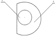
Figure<3〉be the scheme drawing of push-rod piston.
Figure<4〉for managing the scheme drawing of rotating piston.
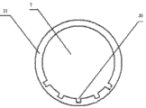
Figure<5〉be the scheme drawing of gear hold down groove.
The present invention includes: the oil device (1) of stopping, push-rod piston (2), machine oil compression chamber (3), ejector sleeve rotating piston (4), hauling block (5), push rod (6), ejector sleeve (7), tractor (8), ejector shell (9), Push Rod Rack (10), fuel transfer pump (11), hauling rope (12), traction sheave (13), main shaft drives gear (14), motor gear (16), has forward and reverse electrical motor (15), push rod driven wheel (17), spring back seat (18), sliding wheel (19), filler port (20), oil cabinet shell (21), store grease chamber (22), more piece spring assembly (23), front end transport pipe (24), brake wheel (25), main shaft (26), rear end transport pipe (27), ejector sleeve skewed slot (28), gear gim peg (29), gear hold down groove (30), gear permanent seat (31).
The specific embodiment
With reference to the accompanying drawings<1〉earlier with ejector shell (9), be installed in below, aircraft carrier deck, ejector and aircraft carrier warship body keeping parallelism, push-rod piston (2) and push rod (6) are reinforced, push rod (6) other end is established gear gim peg (29), put into ejector shell (9) then, again ejector sleeve rotating piston (4) and ejector sleeve (7) are reinforced, be enclosed within then on the push rod (6), more piece spring assembly (23) is enclosed within on the ejector sleeve (7), with push rod driven wheel (17) and main shaft (26), with bearing fixing in ejector shell (9) rear end, with traction sheave (13) and main shaft drives gear (14), be fixed on an end of main shaft (26), brake wheel (25) is fixed on the other end of main shaft (26), motor gear (16), meshing with main shaft drives gear (14), hauling rope (12) one ends connect traction sheave (13), and the other end is connected by hauling block (5) and aircraft and tractor (8) and aircraft.Mounting spring back seat (18) then, spring back seat (18) and oil cabinet shell (21) are reinforced, and establish in filler port (20), the oil cabinet shell (21) oil cabinet shell (21) upper end, installs and fixes a plurality of sliding wheels (19).Gear gim peg (29) is placed in the gear hold down groove (30), gear permanent seat (31) and oil cabinet shell (21) are reinforced, establish fuel transfer pump (11) in front end transport pipe (24) and the rear end transport pipe (27), each is connected two ends with oil cabinet shell (21) with ejector shell (9).
After all parts install, machine oil will be poured in the ejector, actuating motor just changes it at a slow speed then, make multistage spring assembly compression, piston forms the round type attitude gradually under the effect of ejector sleeve skewed slot, at this moment machine oil enters the machine oil compression chamber immediately, hauling rope extends, and starts brake gear then and makes ejector be in arm-to-arm.When aircraft begins to take off, starting fuel transfer pump fills with the compression chamber inner engine oil, and adjust gear according to the aircraft size, turn-on reversal power supply then, make the electrical motor counter-rotating, loosen brake gear simultaneously, make the spring slow expansion, force the reach of push rod and ejector sleeve, the ejector sleeve skewed slot begins to drive ejector sleeve and piston rotation under the effect of push rod driven wheel, make piston form breach and overlapping gradually, at this moment the machine oil of machine oil compression chamber is scurried immediately, the anterior pressure of piston gradually reduces, and spring assembly is expanded gradually, and the rotating speed of electrical motor is progressively accelerated, aircraft safety is taken off, and piston stops to move ahead under oil is stopped the effect of device.
Claims (1)
1. rotary-piston type spring catapult, it is characterized in that: with ejector shell (9), be installed in below, aircraft carrier deck, ejector and aircraft carrier warship body keeping parallelism, push-rod piston (2) and push rod (6) are reinforced, push rod (6) other end is established gear gim peg (29), put into ejector shell (9) then, again ejector sleeve rotating piston (4) and ejector sleeve (7) are reinforced, be enclosed within then on the push rod (6), more piece spring assembly (23) is enclosed within on the ejector sleeve (7), with push rod driven wheel (17) and main shaft (26), with bearing fixing in ejector shell (9) rear end, with traction sheave (13) and main shaft drives gear (14), be fixed on an end of main shaft (26), brake wheel (25) is fixed on the other end of main shaft (26), motor gear (16), meshing with main shaft drives gear (14), hauling rope (12) one ends connect traction sheave (13), the other end is connected by hauling block (5) and aircraft and tractor (8) and aircraft, mounting spring back seat (18) then, spring back seat (18) and oil cabinet shell (21) are reinforced, filler port (20) is established in oil cabinet shell (21) upper end, in the oil cabinet shell (21), install and fix a plurality of sliding wheels (19), gear gim peg (29) is placed in the gear hold down groove (30), gear permanent seat (31) and oil cabinet shell (21) are reinforced, establish fuel transfer pump (11) in front end transport pipe (24) and the rear end transport pipe (27), each is connected two ends with oil cabinet shell (21) with ejector shell (9).
Priority Applications (1)
| Application Number | Priority Date | Filing Date | Title |
|---|---|---|---|
| CN201210587367.9A CN103192995B (en) | 2012-12-30 | 2012-12-30 | Rotary-piston type spring catapult |
Applications Claiming Priority (1)
| Application Number | Priority Date | Filing Date | Title |
|---|---|---|---|
| CN201210587367.9A CN103192995B (en) | 2012-12-30 | 2012-12-30 | Rotary-piston type spring catapult |
Publications (2)
| Publication Number | Publication Date |
|---|---|
| CN103192995A true CN103192995A (en) | 2013-07-10 |
| CN103192995B CN103192995B (en) | 2015-08-26 |
Family
ID=48715852
Family Applications (1)
| Application Number | Title | Priority Date | Filing Date |
|---|---|---|---|
| CN201210587367.9A Expired - Fee Related CN103192995B (en) | 2012-12-30 | 2012-12-30 | Rotary-piston type spring catapult |
Country Status (1)
| Country | Link |
|---|---|
| CN (1) | CN103192995B (en) |
Cited By (1)
| Publication number | Priority date | Publication date | Assignee | Title |
|---|---|---|---|---|
| CN105730708A (en) * | 2016-02-20 | 2016-07-06 | 银世德 | Rotary cylinder type fuel gas ejector |
Citations (6)
| Publication number | Priority date | Publication date | Assignee | Title |
|---|---|---|---|---|
| US3968947A (en) * | 1975-01-14 | 1976-07-13 | All American Industries, Inc. | Launching apparatus for flying device |
| GB2173745A (en) * | 1985-04-18 | 1986-10-22 | Secr Defence | Launcher for unmanned aircraft |
| US5961069A (en) * | 1995-10-18 | 1999-10-05 | Dassault Aviation | Catapult exit shock absorber |
| CN102267571A (en) * | 2011-06-03 | 2011-12-07 | 清华大学 | Spring-pulley combined unmanned aerial vehicle ejector |
| CN202320800U (en) * | 2011-11-29 | 2012-07-11 | 北京思凯飞翔科技有限公司 | Ejection device for unmanned aircraft |
| CN102700721A (en) * | 2012-05-04 | 2012-10-03 | 银世德 | Combined catapult for aircraft carrier |
-
2012
- 2012-12-30 CN CN201210587367.9A patent/CN103192995B/en not_active Expired - Fee Related
Patent Citations (6)
| Publication number | Priority date | Publication date | Assignee | Title |
|---|---|---|---|---|
| US3968947A (en) * | 1975-01-14 | 1976-07-13 | All American Industries, Inc. | Launching apparatus for flying device |
| GB2173745A (en) * | 1985-04-18 | 1986-10-22 | Secr Defence | Launcher for unmanned aircraft |
| US5961069A (en) * | 1995-10-18 | 1999-10-05 | Dassault Aviation | Catapult exit shock absorber |
| CN102267571A (en) * | 2011-06-03 | 2011-12-07 | 清华大学 | Spring-pulley combined unmanned aerial vehicle ejector |
| CN202320800U (en) * | 2011-11-29 | 2012-07-11 | 北京思凯飞翔科技有限公司 | Ejection device for unmanned aircraft |
| CN102700721A (en) * | 2012-05-04 | 2012-10-03 | 银世德 | Combined catapult for aircraft carrier |
Cited By (1)
| Publication number | Priority date | Publication date | Assignee | Title |
|---|---|---|---|---|
| CN105730708A (en) * | 2016-02-20 | 2016-07-06 | 银世德 | Rotary cylinder type fuel gas ejector |
Also Published As
| Publication number | Publication date |
|---|---|
| CN103192995B (en) | 2015-08-26 |
Similar Documents
| Publication | Publication Date | Title |
|---|---|---|
| CN101804866B (en) | Flywheel energy storage accelerating carrier-based aircraft ejector | |
| CN106143941B (en) | A kind of truck platform for the transmitting of small-sized fixed-wing unmanned plane | |
| CN102700721B (en) | Combined catapult for aircraft carrier | |
| CN103434649B (en) | Unmanned aerial vehicle ejecting device slows down and backhaul Gas fluid pressure control system | |
| CN102700720A (en) | Double-tube combined catapult for aircraft carrier | |
| GB2601359A (en) | Aircraft power system | |
| CN103423152B (en) | Vehicle hydraulic pressure vane pump motor and switching controls hydraulic system thereof | |
| CN103192995B (en) | Rotary-piston type spring catapult | |
| CN103466099B (en) | Unmanned measuring machine high speed ejection frame | |
| CN102849223A (en) | Novel spring catapult for aircraft carrier | |
| CN106741877B (en) | A kind of electro-hydraulic ground taxi of multi-wheeled bogie push with from energy regenerative brake combined device | |
| CN102862684A (en) | Novel aircraft carrier flying-off deck | |
| CN108016609B (en) | An aircraft landing gear with self-gliding function | |
| CN104709084A (en) | Automobile hydraulic start/stop system | |
| CN103482078B (en) | A kind of aircraft hydraulic stored-energy ejection system | |
| CN102795348A (en) | Multi-pipe combined ejector of aircraft carrier | |
| CN102717895B (en) | A kind of ejection ejector continuously | |
| CN103359081A (en) | Hub hydraulic pump, kinetic energy recovery and release system and vehicle | |
| CN210942242U (en) | Engine auxiliary starting device for helicopter | |
| CN202686773U (en) | Catapult capable of continuous catapulting | |
| CN103231643B (en) | The two energy-storage system hybrid power passenger car of electricity liquid | |
| CN202541282U (en) | Device for recycling and controlling energy of electricity-liquid proportioned hybrid power of motor automobile | |
| CN103587713A (en) | Spring type ejector for aircraft carrier | |
| CN207826589U (en) | Unmanned plane emitter | |
| CN205908547U (en) | Nacelle gyration hydraulic drive system |
Legal Events
| Date | Code | Title | Description |
|---|---|---|---|
| C06 | Publication | ||
| PB01 | Publication | ||
| C10 | Entry into substantive examination | ||
| SE01 | Entry into force of request for substantive examination | ||
| C14 | Grant of patent or utility model | ||
| GR01 | Patent grant | ||
| CF01 | Termination of patent right due to non-payment of annual fee |
Granted publication date: 20150826 Termination date: 20151230 |
|
| EXPY | Termination of patent right or utility model |