CN103196355A - Back plate detection guiding rule - Google Patents
Back plate detection guiding rule Download PDFInfo
- Publication number
- CN103196355A CN103196355A CN2013100890140A CN201310089014A CN103196355A CN 103196355 A CN103196355 A CN 103196355A CN 2013100890140 A CN2013100890140 A CN 2013100890140A CN 201310089014 A CN201310089014 A CN 201310089014A CN 103196355 A CN103196355 A CN 103196355A
- Authority
- CN
- China
- Prior art keywords
- ruler
- detection
- backboard
- board
- edge
- Prior art date
- Legal status (The legal status is an assumption and is not a legal conclusion. Google has not performed a legal analysis and makes no representation as to the accuracy of the status listed.)
- Granted
Links
Images


Landscapes
- A Measuring Device Byusing Mechanical Method (AREA)
Abstract
Description
技术领域 technical field
本发明涉及一种检测治具,具体涉及一种背板检测靠尺。 The invention relates to a detection jig, in particular to a backboard detection ruler.
背景技术 Background technique
随着技术的发展,LED显示器的尺寸向大型化的方向发展,因此显示器的背板的尺寸也越来越大,在对背板的冲压工艺的要求有所提高的基础上。就对加工出的背板的平面度检测而言,以往的方法已不能实现有效快捷的检测。 With the development of technology, the size of the LED display is developing in the direction of large-scale, so the size of the backplane of the display is also getting larger and larger, based on the increased requirements for the stamping process of the backplane. As far as the flatness detection of the processed backplane is concerned, the previous methods can no longer achieve effective and fast detection.
以往的检测方法是将产品放在大理石平台上等高柱放平后用三坐标检测仪检测产品平面度,由于背板的面积较大,逐点扫描需要很长时间,例如,一个30寸背板检测时间约为1.0~1.2小时。 The previous detection method is to put the product on the marble platform and use the three-coordinate detector to test the flatness of the product. Due to the large area of the back plate, it takes a long time to scan point by point. For example, a 30-inch back plate The plate detection time is about 1.0~1.2 hours.
发明内容 Contents of the invention
为解决现有技术的不足,本发明的目的在于一种操作简单、检测时间短的背板检测靠尺。 In order to solve the deficiencies of the prior art, the object of the present invention is a backboard inspection ruler with simple operation and short inspection time. the
为了实现上述目标,本发明采用如下的技术方案: In order to achieve the above object, the present invention adopts the following technical solutions:
一种背板检测靠尺,包括一个以上的靠尺单元;靠尺单元分为:供人手握持的成板结构的靠板、形成于靠板板面边缘的检测边缘面,靠板具有两个平行且形状相同的板面,检测边缘面垂直于靠板的板面;不同的靠尺单元之间构成固定连接;靠板的板面上设有用于标记识别符号的铭牌区域;检测边缘面上形成有一个以上的直角阶梯结构。 A backboard detection ruler, including more than one ruler unit; the ruler unit is divided into: a board structure for people to hold the board, and a detection edge surface formed on the edge of the board surface. The board has two Two parallel board surfaces with the same shape, the detection edge surface is perpendicular to the board surface against the board; different ruler units form a fixed connection; the board surface against the board is provided with a nameplate area for marking identification symbols; the detection edge surface More than one right-angled ladder structure is formed on the top.
前述的一种背板检测靠尺,不同的靠尺单元为一个一体加工成型的整体。 In the above-mentioned backboard detection ruler, the different ruler units are a whole that is integrally processed and formed.
前述的一种背板检测靠尺,不同的靠尺单元的靠板的板面之间成垂直或平行的关系。 In the aforementioned backboard detection leaner, the board surfaces of the leaner boards of different ruler units are in a vertical or parallel relationship.
前述的一种背板检测靠尺,当靠尺单元的数目为2时,两个靠尺单元的靠板的板面相互垂直。 As for the above-mentioned backboard detection leaner, when the number of the ruler units is 2, the board surfaces of the leaner plates of the two ruler units are perpendicular to each other.
前述的一种背板检测靠尺,靠板板面形状轮廓具有两条平行的直线短边和一条与直线短边垂直的直线长边,直线长边连接两条直线短边的端点,两条直线短边的另外的端点被检测边缘面的边缘所连接;这个检测边缘面的边缘称为检测边缘,检测边缘包括平行于直线短边或直线长边的直线段。 The aforesaid backboard inspection ruler has two parallel straight short sides and a straight straight long side perpendicular to the straight short side, the straight long side connects the endpoints of the two straight short sides, and the two straight line short sides The other endpoints of the short side of the straight line are connected by the edge of the detected edge face; the edge of the detected edge face is called the detected edge, and the detected edge includes a straight line segment parallel to the short side of the straight line or the long side of the straight line.
前述的一种背板检测靠尺,所有的靠尺单元的检测边缘面形成于靠板的板面的同侧。 In the aforementioned backboard detection ruler, the detection edge surfaces of all the ruler units are formed on the same side of the board surface of the backboard.
前述的一种背板检测靠尺,不同的靠尺单元的靠板的板厚均相同。 For the aforementioned backboard detection leaner, the thickness of the leaner boards of different ruler units is the same.
前述的一种背板检测靠尺,由金属材料制成。 The aforementioned backboard detection ruler is made of metal materials.
本发明的有益之处在于:提供一种适用于大尺寸显示器背板的,能有效快捷的实现检测产品平面度的背板检测靠尺。 The advantage of the present invention is that it provides a backboard inspection ruler suitable for large-size display backplanes, which can effectively and quickly detect the flatness of products. the
附图说明 Description of drawings
图1是本发明的一个具有一个靠尺单元的优选实施例的结构示意图; Fig. 1 is a schematic structural view of a preferred embodiment of a ruler unit of the present invention;
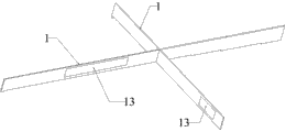
图2是本发明的一个具有两个靠尺单元的优选实施例的结构示意图; Fig. 2 is a schematic structural view of a preferred embodiment of the present invention with two ruler units;
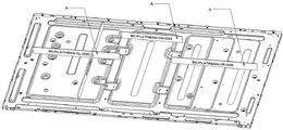
图3是本发明的另一个优选实施例在检测状态下的示意图; Fig. 3 is a schematic diagram of another preferred embodiment of the present invention in a detection state;
图4是本发明的一组优选实例在检测状态下的示意图。 Fig. 4 is a schematic diagram of a group of preferred examples of the present invention in a detection state.
图中附图标记的含义: Meanings of reference signs in the figure:
A、本发明的检测靠尺; A, detection ruler of the present invention;
1、靠尺单元; 1. Ruler unit;
11、靠板,111、板面;112、直线短边,113、直线长边; 11, relying on the board, 111, the board surface; 112, the short side of the straight line, 113, the long side of the straight line;
12、检测边缘面,121、直角阶梯结构,122,检测边缘; 12. Detecting edge surfaces, 121. Right-angled ladder structure, 122, detecting edges;
13、铭牌区域 13. Nameplate area
具体实施方式 Detailed ways
以下结合附图和具体实施例对本发明作具体的介绍。 The present invention will be specifically introduced below in conjunction with the accompanying drawings and specific embodiments.
参照图1至图4所示,本发明的背板检测靠尺A,包括一个以上的靠尺单元1;需要说明的是,不同的靠尺单元1可以采用一体加工成型而作为一个整体。 Referring to Fig. 1 to Fig. 4, the backboard detection ruler A of the present invention includes more than one ruler unit 1; it should be noted that different ruler units 1 can be integrally processed and formed as a whole.
参照图1所示,靠尺单元1分为:供人手握持的成板结构的靠板11、形成于靠板11板面111边缘的检测边缘面12,靠板11具有两个平行且形状相同的板面111,检测边缘面12垂直于靠板11的板面111;不同的靠尺单元1之间构成固定连接;靠板11的板面111上设有用于标记识别符号的铭牌区域13;检测边缘面12上形成有一个以上的直角阶梯结构121。以上是一个靠尺单元1的基本组成。
With reference to shown in Figure 1, the ruler unit 1 is divided into: a
检测边缘面12总的来说由多个平面组成,其主要的作用在于贴合需要检测的部分,从而检测这些部分是否合格。
The
作为一种优选方案,靠板11板面111形状轮廓具有两条平行的直线短边112和一条与直线短边112垂直的直线长边113,直线长边113连接两条直线短边112的端点,两条直线短边112的另外的端点被检测边缘面12的边缘所连接。
As a preferred solution, the profile of the
检测边缘面12的边缘称为检测边缘122,检测边缘122包括平行于直线短边112或直线长边113的直线段。检测边缘122指的检测边缘面12最外缘与板面111相交处的轮廓线,或者说是板面12在此处的轮廓线,这个轮廓线的具体设计应当根据需要检测的情况而定。
The edge of the
需要说明的是所有的靠尺单元1的检测边缘面12形成于靠板11的板面111的同侧,靠尺单元1的靠板11的板厚均相同。
It should be noted that the
根据显示器背板的结构和平面度,制定与标准显示器背板相对应的靠尺单元1的检测边缘面12;检测边缘面12为阶梯结构,阶梯的数目可以根据需要检测的显示器背板上有多少个平面度不同的位置来确定,直角阶梯结构121卡接在这些位置的边缘。根据显示器背板的结构和平面度组合不同的靠尺单元1,并由人手握住靠板11将有检测边缘面12一端的背板检测靠尺A与显示器背板相对应,若可以无缝隙对应即该显示器背板合格,若不能无缝隙对应即该显示器背板不合格。
According to the structure and flatness of the display backplane, formulate the
作为另一种实施例,不同的靠尺单元1的靠板11的板面111之间成垂直或平行的关系;作为一种实施例,背板检测靠尺A可以由金属材料制成。更具体说,当靠尺单元1的数目为2时,两个靠尺单元1的靠板11的板面111相互垂直。这样可以横向纵向一起检测,大大节约了检测时间。
As another embodiment, the
以上显示和描述了本发明的基本原理、主要特征和优点。本行业的技术人员应该了解,上述实施例不以任何形式限制本发明,凡采用等同替换或等效变换的方式所获得的技术方案,均落在本发明的保护范围内。 The basic principles, main features and advantages of the present invention have been shown and described above. Those skilled in the industry should understand that the above-mentioned embodiments do not limit the present invention in any form, and all technical solutions obtained by means of equivalent replacement or equivalent transformation fall within the protection scope of the present invention.
Claims (8)
Priority Applications (1)
| Application Number | Priority Date | Filing Date | Title |
|---|---|---|---|
| CN201310089014.0A CN103196355B (en) | 2013-03-20 | 2013-03-20 | A kind of backboard detection guiding ruler |
Applications Claiming Priority (1)
| Application Number | Priority Date | Filing Date | Title |
|---|---|---|---|
| CN201310089014.0A CN103196355B (en) | 2013-03-20 | 2013-03-20 | A kind of backboard detection guiding ruler |
Publications (2)
| Publication Number | Publication Date |
|---|---|
| CN103196355A true CN103196355A (en) | 2013-07-10 |
| CN103196355B CN103196355B (en) | 2016-08-31 |
Family
ID=48719061
Family Applications (1)
| Application Number | Title | Priority Date | Filing Date |
|---|---|---|---|
| CN201310089014.0A Expired - Fee Related CN103196355B (en) | 2013-03-20 | 2013-03-20 | A kind of backboard detection guiding ruler |
Country Status (1)
| Country | Link |
|---|---|
| CN (1) | CN103196355B (en) |
Citations (1)
| Publication number | Priority date | Publication date | Assignee | Title |
|---|---|---|---|---|
| CN203148368U (en) * | 2013-03-20 | 2013-08-21 | 昆山三景科技股份有限公司 | Backplane detection guiding rule |
Family Cites Families (3)
| Publication number | Priority date | Publication date | Assignee | Title |
|---|---|---|---|---|
| US5090129A (en) * | 1990-12-10 | 1992-02-25 | Cunningham Philip J | Carpenter square |
| CN201852554U (en) * | 2010-11-05 | 2011-06-01 | 广东省韶铸集团有限公司 | Testing tool for smoothness of plate products |
| CN202793296U (en) * | 2012-07-04 | 2013-03-13 | 中建三局第一建设工程有限责任公司 | Detection ruler for planeness of building template |
-
2013
- 2013-03-20 CN CN201310089014.0A patent/CN103196355B/en not_active Expired - Fee Related
Patent Citations (1)
| Publication number | Priority date | Publication date | Assignee | Title |
|---|---|---|---|---|
| CN203148368U (en) * | 2013-03-20 | 2013-08-21 | 昆山三景科技股份有限公司 | Backplane detection guiding rule |
Also Published As
| Publication number | Publication date |
|---|---|
| CN103196355B (en) | 2016-08-31 |
Similar Documents
| Publication | Publication Date | Title |
|---|---|---|
| CN202793288U (en) | Orifice verticality tester for glass tube | |
| CN202649064U (en) | Test template for measuring concrete compressive strength by rebound method | |
| CN102927879A (en) | Detection device for detecting form and location tolerance of irregular structure | |
| CN103196355B (en) | A kind of backboard detection guiding ruler | |
| CN206235284U (en) | A kind of dedicated slot model | |
| CN204347377U (en) | A kind of novel backboard torsion resistance measuring fixture | |
| CN204202561U (en) | A kind of coating dew paper tinsel on-line measuring device | |
| CN203148368U (en) | Backplane detection guiding rule | |
| CN205192440U (en) | Tool is measured to angularity | |
| CN202928486U (en) | Detection device used to detect irregular structure geometric tolerance | |
| CN204495245U (en) | Detect tool | |
| CN104457526A (en) | Gauge for chamfer angle | |
| CN203981071U (en) | A kind of heat exchanger detects tool by Flange Plane | |
| CN202361917U (en) | Device for measuring geometric dimension of silicon chip | |
| CN204269052U (en) | A kind of chamfering cubing | |
| CN209961204U (en) | Auxiliary plate for plate calibration | |
| CN202196760U (en) | Positioning device for front-side dotting of defects on the back side of silicon wafers | |
| CN204757882U (en) | A thickness measurement device for rectangular cell | |
| CN201243429Y (en) | Server frame with formwork | |
| CN205426047U (en) | A new type of flat plate assembly gap measurement plug gauge and combined plug gauge | |
| CN205080233U (en) | A frame for chip automated inspection | |
| CN206876069U (en) | One kind is used for solar energy printing screen plate pattern general quick detecting tool placed in the middle | |
| CN205016205U (en) | Liquid crystal display module testboard and liquid crystal display module test system thereof | |
| CN205009049U (en) | Imitative angle of crystal block device | |
| CN202793352U (en) | Pedestal used for detecting prism rise |
Legal Events
| Date | Code | Title | Description |
|---|---|---|---|
| C06 | Publication | ||
| PB01 | Publication | ||
| C10 | Entry into substantive examination | ||
| SE01 | Entry into force of request for substantive examination | ||
| C14 | Grant of patent or utility model | ||
| GR01 | Patent grant | ||
| CP02 | Change in the address of a patent holder | ||
| CP02 | Change in the address of a patent holder |
Address after: 215335 No. 158 Ruike Road, Kunshan High-tech Zone, Suzhou City, Jiangsu Province Patentee after: KUNSHAN SANJING TECHNOLOGY Co.,Ltd. Address before: 215335, Suzhou, Jiangsu City, Kunshan province Yushan town on the south side of the central ring road Patentee before: KUNSHAN SANJING TECHNOLOGY Co.,Ltd. |
|
| CF01 | Termination of patent right due to non-payment of annual fee | ||
| CF01 | Termination of patent right due to non-payment of annual fee |
Granted publication date: 20160831 |