CN103204111A - Vehicle Door Trim - Google Patents
Vehicle Door Trim Download PDFInfo
- Publication number
- CN103204111A CN103204111A CN2013100102797A CN201310010279A CN103204111A CN 103204111 A CN103204111 A CN 103204111A CN 2013100102797 A CN2013100102797 A CN 2013100102797A CN 201310010279 A CN201310010279 A CN 201310010279A CN 103204111 A CN103204111 A CN 103204111A
- Authority
- CN
- China
- Prior art keywords
- trim
- clip
- vehicle
- wall portion
- door
- Prior art date
- Legal status (The legal status is an assumption and is not a legal conclusion. Google has not performed a legal analysis and makes no representation as to the accuracy of the status listed.)
- Granted
Links
Images




Classifications
-
- B—PERFORMING OPERATIONS; TRANSPORTING
- B60—VEHICLES IN GENERAL
- B60J—WINDOWS, WINDSCREENS, NON-FIXED ROOFS, DOORS, OR SIMILAR DEVICES FOR VEHICLES; REMOVABLE EXTERNAL PROTECTIVE COVERINGS SPECIALLY ADAPTED FOR VEHICLES
- B60J5/00—Doors
- B60J5/04—Doors arranged at the vehicle sides
- B60J5/0412—Lower door structure
- B60J5/0413—Inner panel, e.g. characterised by carrying components
-
- B—PERFORMING OPERATIONS; TRANSPORTING
- B60—VEHICLES IN GENERAL
- B60R—VEHICLES, VEHICLE FITTINGS, OR VEHICLE PARTS, NOT OTHERWISE PROVIDED FOR
- B60R13/00—Elements for body-finishing, identifying, or decorating; Arrangements or adaptations for advertising purposes
- B60R13/02—Internal Trim mouldings ; Internal Ledges; Wall liners for passenger compartments; Roof liners
- B60R13/0237—Side or rear panels
- B60R13/0243—Doors
-
- Y—GENERAL TAGGING OF NEW TECHNOLOGICAL DEVELOPMENTS; GENERAL TAGGING OF CROSS-SECTIONAL TECHNOLOGIES SPANNING OVER SEVERAL SECTIONS OF THE IPC; TECHNICAL SUBJECTS COVERED BY FORMER USPC CROSS-REFERENCE ART COLLECTIONS [XRACs] AND DIGESTS
- Y10—TECHNICAL SUBJECTS COVERED BY FORMER USPC
- Y10T—TECHNICAL SUBJECTS COVERED BY FORMER US CLASSIFICATION
- Y10T29/00—Metal working
- Y10T29/49—Method of mechanical manufacture
- Y10T29/49826—Assembling or joining
Landscapes
- Engineering & Computer Science (AREA)
- Mechanical Engineering (AREA)
- Vehicle Interior And Exterior Ornaments, Soundproofing, And Insulation (AREA)
Abstract
用于车辆的门饰板包括:饰板主体(16),其作为侧门(12)的门内板(24)的内部装饰材料而形成为朝向车厢的内侧膨出;以及夹安装基座(54),其设置在所述饰板主体(16)上的对于所述车辆的后侧区域中,所述夹安装基座(54)包括:夹安置部(64),其配置为与所述门内板(24)相向,并且装配有夹,所述夹安装于形成在所述门内板(24)中的安装孔中;以及夹立壁部(66),其设置为与所述夹安置部(64)连续,并且在水平截面中所述夹立壁部与所述饰板主体和所述夹安置部(64)一起形成闭合截面部,所述夹立壁部(66)包括弯折部(67),所述弯折部具有角度以致向外凸出。

A door trim for a vehicle includes: a trim body (16) formed as an interior trim material of a door inner panel (24) of a side door (12) to bulge toward the inner side of a vehicle compartment; and a clip mounting base (54 ), which is disposed on the trim body (16) in the rear side region of the vehicle, the clip mounting base (54) includes: a clip seating portion (64) configured to be connected to the door The inner panels (24) face each other and are equipped with clips installed in mounting holes formed in the door inner panel (24); (64) is continuous, and in the horizontal section, the clamping vertical wall part forms a closed section together with the trim board main body and the clip placement part (64), and the clamping vertical wall part (66) includes a bent part (67 ), the bent portion has an angle so as to protrude outward.
Description
技术领域technical field
本发明涉及车辆门饰板,尤其涉及其安装结构。The present invention relates to a vehicle door trim, and more particularly to its mounting structure.
背景技术Background technique
根据公开号2011-126489的日本专利申请(JP2011-126489A)中描述的门饰板安装结构,待安装在门内板上的夹安装在夹安装基座上,夹安装基座被布置为使得夹安装基座横跨在饰板主体的立壁部(饰板立壁部)和装饰部(饰板一般部)之间。在与装饰部连续设置的夹安装基座的支柱部处,其上侧的刚度设定得高于下侧的刚度。According to the door trim mounting structure described in Japanese Patent Application Publication No. 2011-126489 (JP2011-126489A), the clip to be mounted on the door inner panel is mounted on the clip mounting base arranged so that the clip The installation base spans between the vertical wall portion of the main body of the trim panel (the vertical wall portion of the trim panel) and the decorative portion (the general portion of the trim panel). At the pillar portion of the clip mounting base provided continuously with the decorative portion, the rigidity of the upper side thereof is set higher than that of the lower side.
根据该现有技术,当乘客由于另一车辆与本车辆的侧面发生碰撞(侧面碰撞)而二次碰撞门饰板时,由于支柱部的上侧和下侧之间的刚度差而在夹安装基座中发生扭曲变形,使得夹安装基座倾斜。因此,假定对乘客的碰撞反作用力能够被抑制。另外,公开号为2008-120128的日本专利申请(JP2008-120128A)和公开号为2009-173197的日本专利申请(JP2009-173197A)也已经公开了其他门饰板安装结构。According to this prior art, when a passenger collides with the door trim a second time due to another vehicle colliding with the side of the own vehicle (side collision), due to the rigidity difference between the upper side and the lower side of the pillar portion, the clip installation Twisting deformation occurs in the base, causing the clip mounting base to tilt. Therefore, it is assumed that the collision reaction force to the passenger can be suppressed. In addition, Japanese Patent Application Publication No. 2008-120128 (JP2008-120128A) and Japanese Patent Application Publication No. 2009-173197 (JP2009-173197A) have also disclosed other door trim installation structures.
但是,因为根据现有技术,夹安装基座的支柱部形成为平行于侧面碰撞负荷的输入方向,所以负荷将支柱部压弯的可能性会高于预期。此外,如果试图使用装饰物等来控制变形模式,则夹安装基座会受装饰物等制约。也就是说,在减少现有技术中的碰撞反作用力方面存在进一步改进空间。However, because according to the prior art, the pillar portion of the clip mounting base is formed parallel to the input direction of the side impact load, there is a possibility that the load will bend the pillar portion more than expected. Also, if an attempt is made to control the deformation mode using decorations, etc., the clip mounting base will be constrained by the decorations or the like. That is to say, there is room for further improvement in reducing the collision reaction force in the prior art.
发明内容Contents of the invention
本发明是考虑上述情况获得的,本发明的目的是提供一种用于车辆的门饰板,其能够在乘客由于另一车辆与本车的侧面碰撞而遭到与车辆门饰板的二次碰撞时有效减弱乘客所接收到的碰撞反作用力。The present invention has been achieved in consideration of the above circumstances, and an object of the present invention is to provide a door trim panel for a vehicle that can be used when a passenger suffers a secondary collision with the vehicle door trim panel due to a side collision between another vehicle and the vehicle. Effectively weaken the collision reaction force received by passengers during a collision.
根据本发明的方案的用于车辆的门饰板包括:饰板主体,其作为侧门的门内板的内部装饰材料而形成为朝向车厢的内侧膨出;以及夹安装基座,其设置在所述饰板主体上的对于所述车辆的后侧区域中,所述夹安装基座包括:夹安置部,其配置为与所述门内板相向,并且装配有夹,所述夹安装于形成在所述门内板中的安装孔中;以及夹立壁部,其设置为与所述夹安置部连续,并且在所述门饰板安装在所述车辆中的状态下,在水平截面中所述夹立壁部与所述饰板主体以及所述夹安置部形成闭合截面部,所述夹立壁部包括弯折部,所述弯折部具有角度以致向所述闭合截面部外凸出。A door trim for a vehicle according to an aspect of the present invention includes: a trim main body formed to bulge toward the inner side of a vehicle compartment as an interior trim material of a door inner panel of a side door; and a clip mounting base provided on the In the area on the rear side of the vehicle on the trim main body, the clip installation base includes: a clip placement portion arranged to face the door inner panel and fitted with a clip mounted on a in the mounting hole in the door inner panel; and a clip standing wall portion which is provided continuously with the clip seating portion, and which, in a horizontal section, in a state in which the door trim is installed in the vehicle, The clamping vertical wall part forms a closed section with the main body of the decorative plate and the clip placement part, and the clamping vertical wall part includes a bent part, and the bent part has an angle so as to protrude outward from the closed cross-sectional part.
根据上述配置,形成为朝向车厢的内侧膨出的所述饰板主体被设置作为所述门内板的内部装饰材料,所述夹安装基座设置在所述饰板主体上的对于所述车辆的后侧区域中。所述夹安装基座具有夹安置部和夹立壁部。所述夹安置部被配置为与所述门内板相向,并且装配有夹,所述夹安装于形成在所述门内板中的安装孔中。将夹安装在安装孔中使得饰板主体安装到门内板上。According to the above configuration, the trim main body formed to bulge toward the inside of the vehicle compartment is provided as the interior trim material of the door inner panel, and the clip mounting base is provided on the trim main body for the vehicle. in the rear area. The clip mounting base has a clip placement portion and a clip standing wall portion. The clip seating part is arranged to face the door inner panel and is fitted with a clip installed in a mounting hole formed in the door inner panel. Installing the clips in the mounting holes allows the trim body to be mounted to the door inner panel.
同时,所述夹立壁部与所述夹安置部连续形成,使得在所述门饰板安装在所述车辆中的状态下,在水平截面中所述夹立壁部与所述饰板主体以及所述夹安置部形成闭合截面部。另外,所述夹立壁部包括弯折部,所述弯折部具有角度以致向所述闭合截面部外侧凸出。At the same time, the clamping upright wall portion and the clamping placement portion are continuously formed so that, in the state where the door trim panel is installed in the vehicle, the clamping upright wall portion and the trim panel main body and the The clip placement portion forms a closed section portion. In addition, the sandwich standing wall portion includes a bent portion having an angle so as to protrude outward of the closed section portion.
当乘客在侧面碰撞中与饰板主体二次碰撞并且冲击负荷输入到夹安装基座时,对应于冲击负荷的碰撞反作用力取决于夹立壁部的压弯负荷。也就是说,夹立壁部的压弯负荷越大,乘客从夹安装基座接收到的碰撞反作用力就越大。When an occupant collides with the trim main body secondary in a side collision and an impact load is input to the clip installation base, the collision reaction force corresponding to the impact load depends on the bending load of the clip upright wall portion. That is, the larger the bending load of the clip standing wall portion, the larger the collision reaction force received by the occupant from the clip mounting base.
因此,根据本发明,夹立壁部包括弯折部。即使冲击负荷输入到夹安装基座,也可降低夹安装基座的碰撞反作用力,因为弯折部不具有力施加点。此外,当碰撞负荷输入到夹安装基座时,应力集中在弯折部处。因此,夹立壁部通过压弯变得易于变形。与夹立壁部设置成大致平行于负荷方向的情形相比,降低了夹立壁部的压弯负荷,使得夹立壁部在初始阶段时的碰撞反作用力的上升量降低了。Therefore, according to the invention, the standing wall portion includes a bent portion. Even if an impact load is input to the clip mounting base, the collision reaction force of the clip mounting base can be reduced because the bent portion has no force application point. In addition, when a collision load is input to the clip mounting base, stress concentrates at the bent portion. Therefore, the sandwich standing wall portion becomes easily deformed by bending. Compared with the case where the vertical wall portion is arranged substantially parallel to the load direction, the bending load of the vertical wall portion is reduced, so that the rising amount of the collision reaction force of the vertical wall portion at the initial stage is reduced.
同时,如果夹立壁部因输入到夹安装基座的冲击负荷通过压弯而变形,使得其向闭合截面区域的内侧弯折,则夹立壁部变得被布置成类似这样的状态:其两个部分堆叠在饰板主体和夹安置部之间。因而,夹立壁部的冲击行程将降低与夹立壁部的两个部分的厚度对应的量,由此会阻止饰板主体的变形并且导致变形的快速结束。Meanwhile, if the clip standing wall portion is deformed by bending due to the impact load input to the clip installation base so that it is bent toward the inside of the closed cross-sectional area, the clip standing wall portion becomes arranged in a state like that its two sides The parts are stacked between the trim body and the clip housing. Thus, the impact stroke of the sandwiched upright wall portion will be reduced by an amount corresponding to the thickness of the two portions of the sandwiched upright wall portion, thereby preventing deformation of the trim body and resulting in a quick end of deformation.
但是,因为根据本发明,夹立壁部的弯折部具有角度以致向夹安装基座的闭合截面部外部凸出,所以当夹立壁部在冲击负荷下通过压弯而变形时,夹立壁部向闭合截面部的外侧弯折。因此,在饰板主体和夹安置部之间,能够确保设计阶段设定的冲击行程。也就是说,当设置了夹立壁部的弯折部时,就提供了夹立壁部的弯折的起始点,这稳定了压弯变形模式。通过弯折部的角度能够容易地调节夹立壁部的压弯负荷。因此,本发明具有的较佳优势在于:能够于乘客在侧面碰撞中与门饰板二次碰撞时有效减弱乘客接收到的碰撞反作用力。However, because according to the present invention, the bent portion of the upright wall portion has an angle so as to protrude toward the outside of the closed section portion of the clip installation base, when the upright wall portion is deformed by bending under an impact load, the upright wall portion is bent toward the outside of the clip mounting base. The outer side of the closed section is bent. Therefore, between the trim main body and the clip placement portion, it is possible to secure the impact stroke set at the design stage. That is, when the bent portion of the sandwiched vertical wall portion is provided, the starting point of the bending of the sandwiched vertical wall portion is provided, which stabilizes the press-bending deformation mode. The bending load of the interposing vertical wall portion can be easily adjusted by the angle of the bent portion. Therefore, the preferred advantage of the present invention is that it can effectively weaken the collision reaction force received by the passenger when the passenger collides with the door trim panel for a second time in a side collision.
在以上本发明的方案中,优选地,所述夹安装基座布置在所述饰板主体上的对于所述车辆的上侧区域中。In the above aspects of the present invention, preferably, the clip installation base is arranged in an upper side region of the trim main body with respect to the vehicle.
通常,当乘客接触饰板主体作为二次碰撞时,因为乘客坐在座位上,所以饰板主体对于车辆的上侧所在的高度对应于乘客的胸部的位置。因而,上述配置能够有效降低乘客的胸部从饰板主体接收到的冲击。因此,本发明具有的较佳优势在于:能够有效抑制乘客接收到的碰撞反作用力。Generally, when the occupant contacts the trim body as a secondary collision, since the occupant sits on the seat, the height of the trim body relative to the upper side of the vehicle corresponds to the position of the occupant's chest. Thus, the above configuration can effectively reduce the impact that the occupant's chest receives from the trim main body. Therefore, the preferred advantage of the present invention is that it can effectively suppress the collision reaction force received by passengers.
在上述本发明的方案中,优选地,所述饰板主体包括:饰板一般部,其形成饰板设计表面;以及饰板立壁部,其设置在所述饰板一般部的外周上并且在车辆宽度方向上向外立起,所述夹安置部从所述饰板立壁部伸出,并且所述夹立壁部布置在所述饰板立壁部对于所述车辆的前方,并且与所述饰板一般部连续地形成。In the solution of the present invention described above, preferably, the trim main body includes: a general portion of the trim forming a design surface of the trim; Standing outward in the width direction of the vehicle, the clip placement portion protrudes from the upright wall portion of the trim panel, and the upright wall portion is arranged in front of the upright wall portion of the trim panel with respect to the vehicle, and is connected to the upright wall portion of the trim panel The plates are generally formed continuously.
根据上述配置,饰板主体包括饰板一般部和饰板立壁部,饰板一般部形成饰板设计表面。此外,饰板立壁部设置在所述饰板一般部的外周上并且形成为在车辆宽度方向上向外立起。因此,饰板主体形成为朝向车厢的内侧膨出。同时,当乘客在侧面碰撞中与饰板主体二次碰撞时,饰板主体在宽区域内变形。由于饰板主体的变形,在饰板主体中从饰板主体的外周(饰板立壁部)到饰板主体内部(饰板一般部)产生张力。According to the above configuration, the trim main body includes the trim general portion and the trim standing wall portion, the trim general portion forming the trim design surface. Further, a trim standing wall portion is provided on the outer periphery of the trim general portion and is formed to stand outward in the vehicle width direction. Therefore, the trim main body is formed to bulge toward the inner side of the vehicle compartment. Meanwhile, when a passenger collides with the trim main body secondary in a side collision, the trim main body is deformed in a wide area. Due to the deformation of the plaque main body, tension is generated in the plaque main body from the outer periphery of the plaque main body (the plaque standing wall portion) to the interior of the plaque main body (the plaque general portion).
此处,在夹安装基座中,夹安置部从饰板立壁部伸出,并且与夹安置部连续的夹立壁部布置在所述饰板立壁部对于所述车辆的前方,并且与所述饰板一般部连续地形成。因而,由于从饰板主体中的饰板立壁部朝向饰板一般部产生的张力而使得夹安装基座变形并且对于车辆向前方下落。当夹安装基座变形并且下落时,碰撞能量被吸收,由此有效减弱了乘客接收到的碰撞反作用力。因此,本发明具有的较佳优势在于:通过使用在饰板主体中产生的张力,夹安装基座变形以吸收冲击能量。Here, in the clip installation base, the clip seating portion protrudes from the trim vertical wall portion, and the clip vertical wall portion continuous with the clip seating portion is arranged in front of the trim vertical wall portion with respect to the vehicle, and is connected to the trim vertical wall portion. The plaque is generally formed continuously. Thus, the clip mounting base deforms and drops forward with respect to the vehicle due to tension generated from the trim vertical wall portion toward the trim general portion in the trim main body. When the clip mounting base is deformed and dropped, the collision energy is absorbed, thereby effectively weakening the collision reaction force received by the passenger. Therefore, the present invention has a preferable advantage in that the clip mounting base is deformed to absorb impact energy by using the tension generated in the trim body.
在上述本发明的方案中,优选地,形成为沿车辆纵向方向波折的阶梯部设置在所述饰板一般部和所述饰板立壁部之间的连接部处,并且所述阶梯部包括朝向所述车厢的所述内侧凸出的松垂部。In the solution of the present invention described above, preferably, a stepped portion formed to meander in the longitudinal direction of the vehicle is provided at the connecting portion between the general portion of the trim panel and the standing wall portion of the trim panel, and the stepped portion includes a direction toward A raised slack portion of the inner side of the carriage.
根据以上配置,当夹安装基座下落时,松垂部伸展以减弱饰板主体的一般部中的张力。也就是说,夹安装基座变得进一步易于下落,由此缓和乘客接收到的冲击。According to the above configuration, when the clip mounting base is dropped, the slack portion is stretched to relax the tension in the general portion of the trim main body. That is, the clip mounting base becomes further easy to drop, thereby alleviating the shock received by the passenger.
在上述本发明的方案中,优选地,所述夹立壁部包括:垂直壁部,其从所述夹安置部的端部起在车辆宽度方向上向内并且对于所述车辆向前延伸;以及倾斜部,其在所述弯折部处与所述垂直壁部形成角度地连接至所述垂直壁部,并且所述倾斜部从所述弯折部起在所述车辆宽度方向上向内并且对于所述车辆向前延伸。In the aspect of the present invention described above, preferably, the clip standing wall portion includes: a vertical wall portion extending inwardly in the vehicle width direction from an end portion of the clip seating portion and forwardly with respect to the vehicle; and an inclined portion connected to the vertical wall portion at an angle to the vertical wall portion at the bent portion, and the inclined portion is inward in the vehicle width direction from the bent portion and For the vehicle to extend forward.
根据以上配置,所述夹立壁部包括垂直壁部和倾斜部,弯折部形成在垂直壁部和倾斜部之间。所述垂直壁部从所述夹安置部的端部在车辆宽度方向上向内并且对于所述车辆向前延伸。因而,所述弯折部相对于所述夹安置部定位在所述车辆宽度方向的内侧以及对于所述车辆的前方。也就是说,所述弯折部不具有力施加点,并且当冲击负荷输入到所述夹安装基座时,指向车辆宽度方向外侧的力矩发生在所述垂直壁部中、围绕所述夹安置部的端部。结果,所述夹立壁部通过压弯而向所述闭合截面部的外侧(向前)变形。因而,存在的较佳优势在于:能够稳定压弯变形模式。According to the above configuration, the standing wall portion includes a vertical wall portion and an inclined portion, and the bent portion is formed between the vertical wall portion and the inclined portion. The vertical wall portion extends inwardly in the vehicle width direction from an end portion of the clip seating portion and forwardly with respect to the vehicle. Thus, the bent portion is positioned on the inner side in the vehicle width direction and forwardly with respect to the vehicle with respect to the clip seating portion. That is, the bent portion has no force application point, and when an impact load is input to the clip mounting base, a moment directed outward in the vehicle width direction occurs in the vertical wall portion around the clip installation. end of the section. As a result, the sandwich standing wall portion is deformed outward (forward) of the closed section portion by press bending. Thus, there is a preferred advantage in that the buckling deformation mode can be stabilized.
在以上配置中,优选地,所述倾斜部相对于所述夹安置部的角度比所述垂直壁部相对于所述夹安置部的角度更接近90°。In the above configuration, preferably, the angle of the inclined portion with respect to the clip seating portion is closer to 90° than the angle of the vertical wall portion with respect to the clip seating portion.
在上述本发明的方案中,优选地,所述弯折部的角度大于90°且小于180°。更优选地,所述弯折部的角度大于120°且小于170°。In the solution of the present invention above, preferably, the angle of the bent portion is greater than 90° and less than 180°. More preferably, the angle of the bent portion is greater than 120° and less than 170°.
当如上所述夹安装基座变形并且下落时,碰撞能量被吸收,由此有效减弱乘客接收到的碰撞反作用力。因而,根据上述配置,所述弯折部的角度设定成大于90°且小于180°,使得夹安装基座随着从饰板主体的饰板立壁部朝向饰板一般部产生的张力而容易变形。因此,存在的较佳优势在于:使用在饰板主体中产生的张力允许夹安装基座下落。When the clip mounting base is deformed and dropped as described above, the collision energy is absorbed, thereby effectively attenuating the collision reaction force received by the passenger. Therefore, according to the above configuration, the angle of the bent portion is set to be larger than 90° and smaller than 180° so that the clip mounting base can be easily attached to the tension generated from the trim vertical wall portion of the trim body toward the trim general portion. out of shape. Thus, there is a preferred advantage in allowing the clip mounting base to drop using the tension created in the trim body.
附图说明Description of drawings
以下将参考附图描述本发明的示例性实施例的特征、优势以及技术和工业重要性,其中类似的附图标记表示类似的元件,附图中:The features, advantages and technical and industrial importance of exemplary embodiments of the invention will now be described with reference to the accompanying drawings, wherein like reference numerals indicate like elements, in which:
图1是侧门的分解立体图,其中使用了根据本发明的实施例的用于车辆的门饰板的安装结构;1 is an exploded perspective view of a side door in which a mounting structure for a door trim panel for a vehicle according to an embodiment of the present invention is used;
图2是门饰板的正视图,其中使用了根据本发明的实施例的用于车辆的门饰板的安装结构;2 is a front view of a door trim in which a mounting structure for a door trim for a vehicle according to an embodiment of the present invention is used;
图3A是沿图2中线3A-3A截取的门饰板的放大剖视图;Figure 3A is an enlarged cross-sectional view of the door trim taken along
图3B是沿图2中线3B-3B截取的门饰板的放大剖视图;Figure 3B is an enlarged cross-sectional view of the door trim taken along
图4A是设置在门饰板上的夹安装基座的立体图,示出了安装有夹的状态;4A is a perspective view of a clip installation base provided on a door trim, showing a state where a clip is installed;
图4B是设置在门饰板上的夹安装基座的立体图,示出了没有安装夹的状态;4B is a perspective view of the clip mounting base provided on the door trim, showing the state without mounting clips;
图5是沿图2中线5-5截取的门饰板的放大剖视图;Fig. 5 is an enlarged cross-sectional view of the door trim taken along line 5-5 in Fig. 2;
图6A至图6C是对应于图5的放大剖视图,示出了图5所示的门饰板的变形过程;6A to 6C are enlarged cross-sectional views corresponding to FIG. 5, showing the deformation process of the door trim shown in FIG. 5;
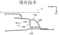
图7A和图7B是对应于图6A和图6B的放大剖视图,示出了对应于图6A和图6B的比较示例;7A and 7B are enlarged cross-sectional views corresponding to FIGS. 6A and 6B, showing comparative examples corresponding to FIGS. 6A and 6B;
图8A和图8B是对应于图4A和图4B的立体图,示出了设置在门饰板上的夹安装基座的变型;Figures 8A and 8B are perspective views corresponding to Figures 4A and 4B, showing a modification of the clip mounting base provided on the door trim;
图9A是沿图2中线9A-9A截取的门饰板的放大剖视图;以及9A is an enlarged cross-sectional view of the door trim taken along
图9B是对应于图9A的放大剖视图,示出了门饰板变形的状态。Fig. 9B is an enlarged sectional view corresponding to Fig. 9A, showing a state in which the door trim is deformed.
具体实施方式Detailed ways
以下,将参考附图描述本发明的实施例。图中的箭头FR表示在车辆的纵向方向上的前方,箭头UP表示在车辆的垂直方向上的上方,箭头OUT表示在车辆宽度方向上的外侧。Hereinafter, embodiments of the present invention will be described with reference to the drawings. Arrow FR in the drawings indicates forward in the longitudinal direction of the vehicle, arrow UP indicates upward in the vertical direction of the vehicle, and arrow OUT indicates outward in the vehicle width direction.
(车辆门饰板的安装结构的配置)(Configuration of the mounting structure of the vehicle door trim)
图1示出了乘客车辆的侧门12的分解侧视图,其应用了本实施例的车辆门饰板的安装结构,侧门12包括门面板14和门饰板16(基础面板18和装饰面板20),当从车厢22的内侧看时门饰板16是饰板主体。图2示出了门饰板16的正视图,其中装饰面板20安装在占据门饰板16的外周的基础面板18的中央部上。1 shows an exploded side view of a
如这些附图所示,门面板14包括门外板(未示出)和门内板24,门内板24构成侧门12的内侧面板。门饰板16安装在门内板24的车辆宽度方向的内侧(车厢22的内部),以便与门内板24相向。门饰板16包括安装在门内板24的车厢22的内侧上的基础面板18和安装在基础面板18上的装饰面板20。As shown in these figures, the
基础面板18是大致矩形的,大致矩形的开口28形成在基础面板18的上部中。如图2所示,开口28如此设计以被装饰面板20封闭。图3A、图3B和图5示出了沿图2中所示的线截取的剖视图,这些附图以放大的方式仅图示了基础面板18的立壁部18A侧。不同于图5,图3A和图3B以简化方式即,以大致直线形状图示了立壁部18A。The
如图3A和图3B所示,立壁部18A从基础面板18的一般部18B起在车辆宽度方向上向外立起,其作为饰板立壁部设置在基础面板18的外边缘上。在基础面板18安装在门内板24上的情况下,在门内板24的一般部24A和基础面板18的一般部18B之间设置有间隙26。也就是说,基础面板18形成为朝向车厢22的内侧膨出。As shown in FIGS. 3A and 3B , standing
如图1所示,能够存储塑料瓶子等的存储部30设置在基础面板18中形成的开口28下方,框架状安装基座表面32形成在沿开口28的周围部上。多个圆形插入孔34设置于安装基座表面32上位于前部(对于车体的纵向方向的前侧)的前框架32A中。除了上述插入孔34之外,在位于安装基座表面32顶部的上框架32B中、位于背部(对于车体的纵向方向的后侧)的背框架32C中以及位于下部的下框架32D中的合适位置处设置矩形接合孔36。As shown in FIG. 1 , a
插入孔34设置于接合孔36对于车辆的纵向方向的前方和后方,并且设置于接合孔36对于车辆的垂直方向的上方和下方。尽管此处未示出,接合孔36设置的高度相当于就坐于座椅上的乘客的胸部位置或腰部位置。The insertion holes 34 are provided at the front and rear of the
另一方面,门扶手21沿车辆的纵向方向设置在装饰面板20对于车辆垂直方向的中央部上。用于提升和下降安装于侧门12等中的侧玻璃(未示出)的电动窗开关(未示出)设置于门扶手21的上表面上。On the other hand, the
如图3A和图3B所示,立壁部20A设置在装饰面板20的外周上,立壁部20A从装饰面板20的一般部20B在车辆宽度方向上向外立起,在装饰面板20和基础面板18之间设置有间隙38。也就是说,装饰面板20被布置成相对于基础面板18的一般部18B朝向车厢22的内侧膨出。此处,以简化方式也即以大致直线形状表示立壁部20A。于是,在本实施例中,装饰面板20的一般部20B和基础面板18的一般部18B被用作饰板一般部。As shown in FIGS. 3A and 3B , an
安装套40和接合片42设置于装饰面板20的外周上,对应于设置在基础面板18的安装基座表面32中的插入孔34和接合孔36。也就是说,安装套40设置于接合片42对于车辆的纵向方向的前方和后方,并且设置于接合片42对于车辆的垂直方向的上方和下方。此处仅示出布置在装饰面板20对于车辆的后部上的安装套40和接合片42。The mounting
如图3A所示,安装套40形成为柱形,尺寸为使得其能够插入形成于基础面板18中的插入孔34中。加强肋44设置于安装套40的周边上使得它们从安装套40的外周表面大致在车辆的垂直方向上以及大致在车辆的纵向方向上被伸展为十字形状。As shown in FIG. 3A , the mounting
加强肋44被设定为具有比安装套40更低的高度,使得安装套40的末端部能够通过插入孔34插入。当安装套40的末端部插入插入孔34中时,安装套40的末端部从安装基座表面32的背面(车辆的外部)暴露,并且通过与安装基座表面32的前表面(车辆的内部)接触的加强肋44的前端面来阻止安装套40的移动。此时,装饰面板20的立壁部20A接触基础面板18的一般部18B。The reinforcing
由于阻止了安装套40的移动,如图3A所示,安装套40的末端部被热封堵,使得安装套40经由溶融部46被固定。因此,装饰面板20经由安装套40联接至基础面板18。Since the movement of the mounting
另一方面,如图3B所示,接合片42以带状形状从装饰面板20的后表面在车辆宽度方向向外并且对于车辆向后延伸,并且对于沿车辆宽度方向的直线倾斜地形成。另外,当从侧向看时向后弯折为大致V形的接合爪50形成在接合片42的末端部处,以便在车辆宽度方向上向内并且对于车辆向后延伸。接合片42能够插入在基础面板18中形成的接合孔36中,并且在接合片42弹性变形的状态下接合爪50被接合孔36的周边固定。On the other hand, as shown in FIG. 3B , the
如图1所示,在门饰板16的车辆上区域A中,夹56和夹安装基座54设置于接合片42和接合孔36附近(在对于车辆的后上侧)。圆形安装孔52形成在门内板24的外周中。夹安装基座54从基础面板18突出。车辆上区域A是门饰板16的位于门饰板16对于车辆的后侧区域中的上侧的区域。尽管夹56和夹安装基座54以适当间隔设置于门饰板16的周边,但是将车辆上区域A中的夹56和夹安装基座54作为设置于门饰板16对于车辆的后侧区域中的夹56和夹安装基座54的例子来描述。As shown in FIG. 1 , in the vehicle upper region A of the
图5图示了沿图2所示的门饰板16的车辆上区域A中的线5-5截取的夹安装基座54的放大剖视图及其周边。如图5所示,立壁部18A设置在基础面板18的一般部18B的外周上。在一般部18B的立壁部18A侧,阶梯部58被设置成在车辆的纵向方向上波折,松垂部60,62被设置成朝向车厢22的内侧凸出。5 illustrates an enlarged cross-sectional view of the
夹安装基座54形成为当沿车辆的纵向方向截取时具有L形截面。夹安装基座54跨接在基础面板18的一般部18B和立壁部18A之间。夹安装基座54包括夹安置部64和夹立壁部66,夹安置部64与基础面板18的立壁部18A连续形成。The
夹安置部64从立壁部18A对于车辆向前延伸,并且能够与门内板24相向,也就是说,其配置为定位成平行于门内板24。夹立壁部66从夹安置部64的端部在车辆宽度方向上向内延伸,并且夹立壁部66与基础面板18的一般部18B连续形成。于是,在水平截面中,由基础面板18和夹安装基座54形成闭合截面区域65。The
大致在夹立壁部66的高度方向的中央部中或沿车辆宽度方向的中央部中,设置有弯折部67,其具有角度θ以便在闭合截面区域65的外部凸出。垂直壁部66A从夹立壁部66中的夹安置部64的端部在车辆宽度方向上向内并且对于车辆向前延伸,倾斜部66B从垂直壁部66A在车辆宽度方向上向内并且对于车辆向前延伸。Approximately in the central portion in the height direction or in the vehicle width direction of the sandwiching standing
也就是说,垂直壁部66A和倾斜部66B均对于彼此倾斜以便对于车辆向前凸出。弯折部67形成在倾斜部66B和垂直壁部66A之间。倾斜部66B相对于夹安置部64的角度比垂直壁部66A相对于夹安置部64的角度更陡,或更接近90°。此处作为例子,由垂直壁部66A和倾斜部66B限定的弯折部67的角度θ设定为近似于165°。优选地,弯折部67的角度θ设定在90°<θ<180°范围内。更优选的是,弯折部的角度θ是120°<θ<170°。That is, both the
另一方面,如图4A和图4B所示,夹56能够安装在夹安装基座54的夹安置部64上。如图4A所示,夹56具有可弹性变形的锥形部68,如图5所示,锥形部68压入门内板24中的安装孔52中。凸缘70设置在锥形部68的基底部处,并且能够接触安装孔52的周边。On the other hand, as shown in FIGS. 4A and 4B , the
颈部72和凸缘部74穿过凸缘部70在与锥形部68反向的一侧上被设置成与凸缘部70一体,夹安置部64能够夹在凸缘部74和凸缘部70之间。如图4B所示,插入孔69形成在夹立壁部66中,颈部72和凸缘部74(关于二者见图5)能够置于插入孔69中。此外,与插入孔69联通的联接孔64A设置在夹安置部64中。凸起76设置在联接孔64A的周边部上的插入孔69侧,联接孔64A位于凸起76之间。The neck portion 72 and the
在将颈部72和凸缘部74插入到插入孔69的过程中,如图4A所示,当凸缘部70坐落于凸起76上时,阻止凸缘部70脱出,使得夹56经由凸缘部70相对于夹安置部64定位。于是,在该状态下,颈部72布置在联接孔64A内,并且联接孔64A的周围部被凸缘部70和凸缘部74夹在中间。在该状态下,夹56联接至夹安装基座54。In the process of inserting the neck portion 72 and the
如图5所示,夹56的锥形部68压入门内板24的安装孔52,安装孔52的周围部被锥形部68和凸缘部70夹在中间,使得夹56安装在安装孔52中。因此,门饰板16经由夹56被安装至门内板24。As shown in FIG. 5, the tapered
(车辆门饰板的安装结构的操作和效果)(Operation and effect of the installation structure of the vehicle door trim)
如图1所示,门饰板16包括基础面板18和装饰面板20,装饰面板20联接到基础面板18的内侧。插入孔34和接合孔36形成在安装基座表面32中,安装基座表面32设置于在基础面板18中形成的开口28的周围部处。As shown in FIG. 1 , the door trim 16 includes a
通过如图3A所示将形成在装饰面板20上的安装套40插入插入孔34中并且将安装套40的末端部热封堵,装饰面板20被固定至基础面板18。在该状态下,形成在装饰面板20和基础面板18之间的间隙38填充有安装套40和加强肋44。因此,装饰面板20经由安装套40和加强肋44稳固地联接至基础面板18。也就是说,装饰面板20相对于基础面板18被安装套40和加强肋44支撑,使得装饰面板20很难偏转。因而,确保了门饰板16在正常使用寿命中的刚度。The
如图3B所示,将形成在装饰面板20上的接合片42插入接合孔36中,并且在接合片42弹性变形的状态下由接合孔36的周边固定接合爪50。结果,经由接合片42施加了将装饰面板20在车辆宽度方向上向外挤压的压紧力,使得在装饰面板20中产生抵抗压紧力的反作用力。因而,装饰面板20在该部分能够确保必要的刚度。于是,如果当另一车辆从侧向与给定车辆碰撞时,乘客与其门饰板16二次碰撞并且装饰面板20朝向基础面板18侧变形,则解除了接合片42的接合爪50与接合孔36的周边的接合,由此减弱了侧面碰撞时由于乘客的二次碰撞引起的碰撞反作用力。因而,能够确保在乘客的二次碰撞时抵抗侧面碰撞的性能。As shown in FIG. 3B , the
如图5所示,作为夹安装基座54的一部分的夹立壁部66包括:垂直壁部66A,其位于夹安置部64侧;以及倾斜部66B,其位于基础面板18侧。弯折部67由垂直壁部66A和倾斜部66B形成,弯折部67向由基础面板18和夹安装基座54形成的闭合截面区域65的外侧弯折。As shown in FIG. 5 , the clip standing
当乘客与门饰板16二次碰撞时,抵抗冲击负荷的碰撞反作用力取决于夹立壁部66的压弯负荷。也就是说,随着夹立壁部66的压弯负荷增加,乘客从夹安装基座54接收到的碰撞反作用力相应地增加。When the occupant collides with the door trim 16 for the second time, the collision reaction force against the impact load depends on the bending load of the interposing
因此,根据本实施例,如上所述,弯折部67设置在夹立壁部66上。当冲击负荷输入到夹安装基座54时,应力集中在弯折部67处。因此,夹立壁部66通过压弯而容易变形。与夹立壁部设置成大致平行于负荷方向的情形(未示出)相比,夹立壁部66的压弯负荷降低了,使得降低了夹立壁部66在开始阶段碰撞反作用力的上升量。Therefore, according to the present embodiment, as described above, the
假定如图7A和图7B所示,当乘客F的二次碰撞发生时,夹立壁部102因输入到夹安装基座100的冲击负荷通过压弯而变形并且向闭合截面区域104的内侧弯折。在这种情况下,尽管未示出,夹立壁部102变成处于在闭合截面区域104内其两个部分堆叠在门饰板106和夹安置部108之间的状态。因而,夹立壁部102的冲击行程减小了与夹立壁部102的两个部分的厚度对应的量,由此阻止了门饰板106变形从而加速了变形的结束。Assume that, as shown in FIGS. 7A and 7B , when a secondary collision of the passenger F occurs, the clip standing
但是,根据本实施例,如图6A所示,设置在夹立壁部66上的弯折部67向夹安装基座54的闭合截面区域65的外侧弯折(由此具有角度)。在这种情况下,如图6B和图6C所示,当由于乘客F的二次碰撞而使得冲击负荷输入到夹安装基座54时,夹立壁部66通过压弯而变形并且夹立壁部66向闭合截面区域65的外侧弯折。However, according to the present embodiment, as shown in FIG. 6A , the
因而,能够在门饰板16和夹安置部64之间确保在设计阶段设定的冲击行程。也就是说,夹立壁部66中的弯折部67被设置成提供了夹立壁部66的弯折的起始点以便稳定压弯变形模式。因此,能够有效减弱当乘客F在侧面碰撞中与门饰板二次碰撞时的碰撞反作用力。同时,能够取决于弯折部67的角度θ来容易地调节夹立壁部66的压弯负荷。Thus, the impact stroke set at the design stage can be ensured between the
如图5所示,垂直壁部66A从夹立壁部66的夹安置部64的端部在车辆宽度方向上向内延伸并且对于车辆向前延伸,倾斜部66B从垂直壁部66A在车辆宽度方向上向内延伸并且对于车辆向前延伸。弯折部67形成在倾斜部66B和垂直壁部66A之间。As shown in FIG. 5 , the
因而,弯折部67相对于夹安置部64被定位在车辆宽度方向上的内侧和对于车辆的前方。也就是说,弯折部67不具有力施加点,并且当冲击负荷输入到夹安装基座54时,指向车辆宽度方向外侧的力矩M发生在垂直壁部66A中、围绕夹安置部64的端部。结果,夹立壁部66通过压弯而向闭合截面区域65的外侧变形。因而,能够进一步稳定压弯变形模式。Thus, the
如图6A至图6C所示,随着夹安装基座54变形并且下落,吸收冲击能量,由此有效减弱乘客F接收到的碰撞反作用力。基于此原因,根据本实施例,垂直壁部66A和倾斜部66B随着它们接近弯折部67而对于车辆向前倾斜。As shown in FIGS. 6A to 6C , as the
此处,尽管由于乘客F的二次碰撞而使得门饰板16在宽区域中变形,但是由于门饰板16的变形而从立壁部18A朝向一般部18B在门饰板16中产生张力。在夹安装基座54设置在门饰板16的对于车辆的后侧区域时,张力T1主要产生在车辆的向前方向上。Here, although the door trim 16 is deformed in a wide area due to the secondary collision of the passenger F, tension is generated in the door trim 16 from the standing
因而,根据本实施例,与垂直壁部66A或倾斜部66B形成为平行于车辆宽度方向的情形相比,夹安装基座54更易于因门饰板16中产生的张力T1而变形。也就是说,使用张力Tl允许夹安装基座54下落。同时不用说,垂直壁部66A或倾斜部66B当然可以形成为平行于车辆宽度方向。Thus, according to the present embodiment, clip mounting
夹安装基座54形成为跨接在基础面板18的一般部18B和垂直壁部18A之间。也就是说,在夹安装基座54的闭合截面部65内,沿车辆的纵向方向,没有壁在夹安置部64和夹立壁部66之间伸展。The
因此,夹安装基座54容易被张力T1影响。也就是说,当门饰板16中产生张力T1时,夹安装基座54变形并且下落从而吸收冲击能量。结果,能够有效减弱乘客F接收到的碰撞反作用力。Therefore, the
如图5所示,阶梯部58形成在基础面板18的一般部18B的立壁部18A侧以便在车辆的纵向方向上波折,并且松垂部60、62设置成向车厢22的内侧突出。因而,如图6A至图6C所示,当夹安装基座54下落时,松垂部60、62伸展以减弱门饰板16的一般部18B中的张力。也就是说,夹安装基座54变得进一步易于下落,由此缓和乘客F接收到的冲击。As shown in FIG. 5 , a stepped
(夹安装基座的变型)(variation of clip mount base)
如图5所示,门饰板16经由夹56安装至门内板24。当夹56安装在安装孔52中时,通常,将夹56压入安装孔52。为此目的,夹安装基座54需要具有能够承受将夹56压入门内板24中的安装孔52的压紧力(轴向力)N的刚度。As shown in FIG. 5 , the door trim 16 is mounted to the
因而,根据本实施例,如图8A所示,肋78从夹立壁部66向车辆下方延伸,肋78与基础面板18的一般部18B设置为一体。当沿车辆的纵向方向看时肋78具有三角形形状,并且定形为从夹安置部64侧朝向一般部18B逐渐扩张。Therefore, according to the present embodiment, as shown in FIG. 8A , the
结果,如图5所示,当夹安装基座54上的夹56被压入安装孔52时,能够降低在车辆宽度方向上输入的基于轴向力N的接触压力,由此减弱夹安装基座54中产生的应力。As a result, as shown in FIG. 5, when the
当夹56安装在安装孔52中时,如图9A和图9B所示,在夹安装基座54的车辆的垂直方向上产生张力T2,T3。因为夹安装基座54被布置在门饰板16的相对于车辆的上侧,所以在夹安装基座54中车辆的向下方向上产生的张力T3大于在车辆的向上方向上产生的张力T2。因而,从夹安装基座54的夹立壁部66向车辆下方突出的肋78能够防止夹安装基座54受到损坏,由此防止因夹安装基座54的压弯而导致的变形。When the
因为与一般部18B一体形成的肋78从夹安装基座54的夹立壁部66突出,所以夹安装基座54中夹立壁部66的区域增加了与根据本变型所提供的肋78相对应的量。因而,当在车辆的向前方向上施加张力T1(见图6A)时,随着一般部18B的变形,夹立壁部66变得更易于下落,由此进一步利于夹安装基座54的变形。Since the
尽管如图5所示已经描述了当将夹56压入安装孔52时,输入至夹安装基座54的轴向力N是在车辆宽度方向上输入的,但是取决于门饰板16的形状,轴向力N可以与车辆宽度方向斜向输入。在这种情况下,从确保夹安装基座54的刚度的角度来说,将肋78设置在夹安置部61侧也许更好。Although it has been described that the axial force N input to the
尽管,如图8A所示,肋78从夹安装基座54的夹立壁部66对于车辆向下突出,但是肋可以对于车辆向上突出。因为夹安装基座54设置在对于车辆的上侧上,所以如上所述,在夹安装基座54中车辆的向下方向上产生的张力T3大于在车辆的向上方向上产生的张力T2。因而,相对于夹安装基座54在车辆下侧的门饰板16变形得更大。因而,从夹立壁部66侧起向车辆下方突出的肋78对于夹安装基座54的变形来说更有效。Although, as shown in FIG. 8A , the
此外,如图8B所示,在夹安装基座54的夹立壁部66和基础面板18的一般部18B之间的连接部(脊部)80或在夹安装基座54的夹安置部64和基础面板18的立壁部18A之间的连接部82可以设置有支撑件84,其沿车辆的纵向方向布置在夹安装基座54的内侧以加强连接部80、82。In addition, as shown in FIG. 8B , the connecting portion (ridge) 80 between the clip standing
因此,当门饰板16安装至门内板24(见图5)时,能够抑制夹安装基座54的压弯变形。尽管为了作图的方便将支撑件84示为在连接部82对于车辆的下侧,但是,如果支撑件84设置在连接部82的在车辆的垂直方向上的中央部,则当夹安装基座54下落时支撑件84进入安装孔64A或插入孔69,由此不会阻碍夹安装基座54的下落。Therefore, when the door trim 16 is mounted to the door inner panel 24 (see FIG. 5 ), the buckling deformation of the
(本实施例的补充)(supplement to this example)
通常,当作为二次碰撞乘客接触门饰板16时,因为乘客坐在座位上,所以如图2所示的门饰板16的区域A所在的高度对应于乘客的胸部的位置。因而,在门饰板16的区域A中根据本实施例的基础面板18包括夹安装基座54的配置有效减弱了乘客的胸部从门饰板16接收到的碰撞反作用力。不用说,除了门饰板16的对于车辆的后侧区域中的区域A,基础面板18包括夹安装基座54的配置当然也可以应用于门饰板16的其他区域。Generally, when a passenger touches the door trim 16 as a secondary collision, the area A of the door trim 16 as shown in FIG. 2 is located at a height corresponding to the position of the passenger's chest because the passenger is sitting on the seat. Thus, the configuration in which the
此外,尽管如图5所示,根据本实施例,门饰板16由基础面板18和装饰面板20形成,但是门饰板16可以通过将基础面板18和装饰面板20整体模制而形成。Furthermore, although the door trim 16 is formed of the
此外,尽管根据本实施例,夹安装基座54形成为使得夹安装基座54沿车辆的纵向方向截取的截面形状是L形,但是夹安装基座54可以是任何形状,只要当沿车辆的纵向方向施加的负荷输入到门饰板16时夹安装基座54下落。因而,夹安装基座54的截面形状不必须是L形。Furthermore, although according to the present embodiment, the
尽管在本实施例中图示和描述了枢转型侧门12,但是本发明可以应用于滑动型侧门。Although the pivot
尽管以上描述了本发明的一个实施例,但是本发明不限于上述例子。不用说,本发明当然也可以在其范围内实施为各种变形而不偏离其要点。Although one embodiment of the present invention has been described above, the present invention is not limited to the above examples. It goes without saying that the present invention can of course also be implemented in various modifications within its scope without departing from its gist.
Claims (8)
Applications Claiming Priority (2)
| Application Number | Priority Date | Filing Date | Title |
|---|---|---|---|
| JP2012-004127 | 2012-01-12 | ||
| JP2012004127A JP5899937B2 (en) | 2012-01-12 | 2012-01-12 | Mounting structure for automotive door trim |
Publications (2)
| Publication Number | Publication Date |
|---|---|
| CN103204111A true CN103204111A (en) | 2013-07-17 |
| CN103204111B CN103204111B (en) | 2015-09-02 |
Family
ID=48751586
Family Applications (1)
| Application Number | Title | Priority Date | Filing Date |
|---|---|---|---|
| CN201310010279.7A Expired - Fee Related CN103204111B (en) | 2012-01-12 | 2013-01-10 | Vehicle Door Trim |
Country Status (3)
| Country | Link |
|---|---|
| US (1) | US8801075B2 (en) |
| JP (1) | JP5899937B2 (en) |
| CN (1) | CN103204111B (en) |
Cited By (2)
| Publication number | Priority date | Publication date | Assignee | Title |
|---|---|---|---|---|
| CN107804244A (en) * | 2016-09-08 | 2018-03-16 | 福特全球技术公司 | Use the pelvis load management of the integrated crushable structures in door trim |
| CN108297656A (en) * | 2017-01-13 | 2018-07-20 | 通用汽车环球科技运作有限责任公司 | Postpone vehicle inside door when for side collision and adorns the system and method being detached from from the metallic plate of door |
Families Citing this family (15)
| Publication number | Priority date | Publication date | Assignee | Title |
|---|---|---|---|---|
| US9382732B2 (en) * | 2011-01-21 | 2016-07-05 | GM Global Technology Operations LLC | Door assembly with anti-theft device |
| US8985674B2 (en) * | 2011-08-02 | 2015-03-24 | Toyota Boshoku Kabushiki Kaisha | Door trim for vehicle |
| US8979156B2 (en) * | 2013-03-22 | 2015-03-17 | Nissan North America, Inc. | Vehicle panel attachment arrangement |
| JP6052029B2 (en) * | 2013-04-04 | 2016-12-27 | トヨタ紡織株式会社 | Interior materials for vehicles |
| US9174586B2 (en) * | 2013-11-08 | 2015-11-03 | Nyx, Inc. | Storage compartment apparatus for door of a vehicle |
| CN103640528B (en) * | 2013-12-13 | 2015-09-30 | 宁波明佳汽车内饰有限公司 | Automobile door plate assembling chute buckle |
| KR101637303B1 (en) * | 2014-11-21 | 2016-07-07 | 현대자동차 주식회사 | Door structure for motor vehicle |
| US10406893B2 (en) * | 2016-06-29 | 2019-09-10 | GM Global Technology Operations LLC | Inner support panel for mounting a hardware module of a vehicle door assembly |
| JP6585015B2 (en) * | 2016-07-25 | 2019-10-02 | トヨタ紡織株式会社 | Interior materials for vehicles |
| US10145401B2 (en) * | 2017-01-26 | 2018-12-04 | Ford Global Technologies, Llc | Clip for a vehicle door assembly |
| US10780844B2 (en) * | 2018-06-27 | 2020-09-22 | Ford Global Technologies, Llc | Fastening system for securing a trim panel to a support substrate |
| JP7408252B2 (en) * | 2021-01-28 | 2024-01-05 | ダイハツ工業株式会社 | Vehicle interior parts |
| JP7567654B2 (en) | 2021-05-21 | 2024-10-16 | トヨタ紡織株式会社 | Vehicle interior materials |
| WO2024010918A1 (en) * | 2022-07-08 | 2024-01-11 | Consolidated Metco, Inc. | Vehicle door and method of manufacture |
| CN117124827A (en) * | 2023-10-09 | 2023-11-28 | 上汽通用汽车有限公司 | Door interior panel installation and adjustment mechanism and vehicle |
Citations (3)
| Publication number | Priority date | Publication date | Assignee | Title |
|---|---|---|---|---|
| US6126230A (en) * | 1996-12-24 | 2000-10-03 | Toyota Jidosha Kabushiki Kaisha | Energy absorbing structure for automobile |
| CN101795904A (en) * | 2007-10-11 | 2010-08-04 | 丰田自动车株式会社 | Vehicle inner panel |
| JP2011126489A (en) * | 2009-12-21 | 2011-06-30 | Toyota Motor Corp | Door trim mounting structure and door trim |
Family Cites Families (12)
| Publication number | Priority date | Publication date | Assignee | Title |
|---|---|---|---|---|
| JP2548057Y2 (en) * | 1991-07-09 | 1997-09-17 | 日産自動車株式会社 | Automotive door trim mounting structure |
| US5169204A (en) * | 1992-04-08 | 1992-12-08 | Davidson Textron Inc. | Energy absorbing inner door panel with fasteners to absorb body impact energy |
| JP3435866B2 (en) * | 1994-12-27 | 2003-08-11 | 日産自動車株式会社 | Automotive side trim mounting structure |
| US6149224A (en) * | 1999-06-11 | 2000-11-21 | Delphi Technologies, Inc. | Break away trim panel assembly |
| JP3633537B2 (en) * | 2001-09-27 | 2005-03-30 | トヨタ自動車株式会社 | Mounting structure for interior parts for vehicles |
| JP2006069347A (en) * | 2004-09-01 | 2006-03-16 | Kasai Kogyo Co Ltd | Shock absorption pad mounting structure |
| JP2008120128A (en) | 2006-11-08 | 2008-05-29 | Kasai Kogyo Co Ltd | Clip mounting seat structure |
| JP5125545B2 (en) | 2008-01-25 | 2013-01-23 | トヨタ紡織株式会社 | Clip seat mounting structure and door trim mounting structure |
| US7726726B2 (en) * | 2008-02-19 | 2010-06-01 | Gm Global Technology Operations, Inc. | Energy-absorbing system for vehicle door assembly |
| US7677640B2 (en) * | 2008-05-23 | 2010-03-16 | Nissan Technical Center North America, Inc. | Panel assembly for a vehicle |
| JP2010264971A (en) * | 2009-04-14 | 2010-11-25 | Toyota Boshoku Corp | Mounting structure of resin impact absorber for side impact |
| US8020921B2 (en) * | 2009-08-17 | 2011-09-20 | Toyota Motor Engineering & Manufacturing North America, Inc. | Door trim panel having temporary support and pivot members and method of installing the door trim panel |
-
2012
- 2012-01-12 JP JP2012004127A patent/JP5899937B2/en not_active Expired - Fee Related
-
2013
- 2013-01-10 US US13/738,369 patent/US8801075B2/en active Active
- 2013-01-10 CN CN201310010279.7A patent/CN103204111B/en not_active Expired - Fee Related
Patent Citations (3)
| Publication number | Priority date | Publication date | Assignee | Title |
|---|---|---|---|---|
| US6126230A (en) * | 1996-12-24 | 2000-10-03 | Toyota Jidosha Kabushiki Kaisha | Energy absorbing structure for automobile |
| CN101795904A (en) * | 2007-10-11 | 2010-08-04 | 丰田自动车株式会社 | Vehicle inner panel |
| JP2011126489A (en) * | 2009-12-21 | 2011-06-30 | Toyota Motor Corp | Door trim mounting structure and door trim |
Cited By (4)
| Publication number | Priority date | Publication date | Assignee | Title |
|---|---|---|---|---|
| CN107804244A (en) * | 2016-09-08 | 2018-03-16 | 福特全球技术公司 | Use the pelvis load management of the integrated crushable structures in door trim |
| CN107804244B (en) * | 2016-09-08 | 2023-08-25 | 福特全球技术公司 | Pelvis load management with integrated crushable structure in door trim |
| CN108297656A (en) * | 2017-01-13 | 2018-07-20 | 通用汽车环球科技运作有限责任公司 | Postpone vehicle inside door when for side collision and adorns the system and method being detached from from the metallic plate of door |
| CN108297656B (en) * | 2017-01-13 | 2021-07-13 | 通用汽车环球科技运作有限责任公司 | System and method for delaying detachment of interior door trim of vehicle in case of side collision |
Also Published As
| Publication number | Publication date |
|---|---|
| JP2013141944A (en) | 2013-07-22 |
| US8801075B2 (en) | 2014-08-12 |
| CN103204111B (en) | 2015-09-02 |
| JP5899937B2 (en) | 2016-04-06 |
| US20130181475A1 (en) | 2013-07-18 |
Similar Documents
| Publication | Publication Date | Title |
|---|---|---|
| CN103204111B (en) | Vehicle Door Trim | |
| US6893077B1 (en) | Door trim panel having deformable armrest | |
| US7497503B2 (en) | Vehicle front structure | |
| CN108327499A (en) | Automobile | |
| US8714641B2 (en) | Vehicle seat | |
| US10793100B2 (en) | Automobile cowl grille structure | |
| EP2894060B1 (en) | Vehicle seat | |
| CN102695631A (en) | Vehicle bumper structure | |
| EP2894062A1 (en) | Vehicle seat, and seat frame for vehicle seat | |
| JP2012101697A (en) | Cowl top cover | |
| JP6706718B2 (en) | Interior parts for vehicles | |
| JP2005289237A (en) | Cowl top cover | |
| JP4075814B2 (en) | Body cowl structure | |
| KR101734814B1 (en) | Manufacturing method and apparatus for suspension assembly and suspension assembly thereof | |
| JP6810622B2 (en) | Battery protection structure for driving automobiles | |
| JP2005280628A (en) | Cowl top cover | |
| JP2009035233A (en) | Body structure | |
| JP5817493B2 (en) | Mounting structure for automotive door trim | |
| JP5724863B2 (en) | Mounting structure for automotive door trim | |
| JP6623953B2 (en) | Vehicle superstructure | |
| JP4951468B2 (en) | Vehicle intake duct | |
| JP7430594B2 (en) | cowl top cover | |
| JP7294221B2 (en) | passenger protection device | |
| JP2012144124A (en) | Shock absorbing structure for vehicle | |
| JP3946110B2 (en) | Instrument panel structure of vehicle |
Legal Events
| Date | Code | Title | Description |
|---|---|---|---|
| C06 | Publication | ||
| PB01 | Publication | ||
| C10 | Entry into substantive examination | ||
| SE01 | Entry into force of request for substantive examination | ||
| C14 | Grant of patent or utility model | ||
| GR01 | Patent grant | ||
| C53 | Correction of patent of invention or patent application | ||
| CI03 | Correction of invention patent |
Correction item: Claims Correct: Correct False: Error Number: 35 Page: Description Volume: 31 |
|
| CF01 | Termination of patent right due to non-payment of annual fee |
Granted publication date: 20150902 |
|
| CF01 | Termination of patent right due to non-payment of annual fee |