CN1032694A - Pneumatic starter - Google Patents
Pneumatic starter Download PDFInfo
- Publication number
- CN1032694A CN1032694A CN 88103356 CN88103356A CN1032694A CN 1032694 A CN1032694 A CN 1032694A CN 88103356 CN88103356 CN 88103356 CN 88103356 A CN88103356 A CN 88103356A CN 1032694 A CN1032694 A CN 1032694A
- Authority
- CN
- China
- Prior art keywords
- cylinder
- starting
- air
- rotor
- slide plate
- Prior art date
- Legal status (The legal status is an assumption and is not a legal conclusion. Google has not performed a legal analysis and makes no representation as to the accuracy of the status listed.)
- Pending
Links
- 239000007858 starting material Substances 0.000 title abstract description 16
- 238000002485 combustion reaction Methods 0.000 claims abstract description 28
- 230000005540 biological transmission Effects 0.000 claims abstract description 8
- -1 ferrous metals Chemical class 0.000 abstract description 2
- 229910052751 metal Inorganic materials 0.000 abstract description 2
- 239000002184 metal Substances 0.000 abstract description 2
- 230000000694 effects Effects 0.000 description 5
- 239000000314 lubricant Substances 0.000 description 5
- 230000006835 compression Effects 0.000 description 4
- 238000007906 compression Methods 0.000 description 4
- 238000003756 stirring Methods 0.000 description 3
- 238000000034 method Methods 0.000 description 2
- 238000007789 sealing Methods 0.000 description 2
- XLYOFNOQVPJJNP-UHFFFAOYSA-N water Substances O XLYOFNOQVPJJNP-UHFFFAOYSA-N 0.000 description 2
- 238000010276 construction Methods 0.000 description 1
- 239000000945 filler Substances 0.000 description 1
- 239000012467 final product Substances 0.000 description 1
- 238000010304 firing Methods 0.000 description 1
- 238000002347 injection Methods 0.000 description 1
- 239000007924 injection Substances 0.000 description 1
- 229910052743 krypton Inorganic materials 0.000 description 1
- DNNSSWSSYDEUBZ-UHFFFAOYSA-N krypton atom Chemical compound [Kr] DNNSSWSSYDEUBZ-UHFFFAOYSA-N 0.000 description 1
- 230000007774 longterm Effects 0.000 description 1
- 238000012423 maintenance Methods 0.000 description 1
- 239000003208 petroleum Substances 0.000 description 1
- 238000004321 preservation Methods 0.000 description 1
- 230000002035 prolonged effect Effects 0.000 description 1
- 230000005855 radiation Effects 0.000 description 1
- 238000012857 repacking Methods 0.000 description 1
- 239000002699 waste material Substances 0.000 description 1
Images


Landscapes
- Valve Device For Special Equipments (AREA)
Abstract
Pneumatic starter the present invention relates to the starting arrangement of internal-combustion engine, is particularly useful for the ignitor of IC engine of vehicle.It partly is made up of air supply system, power mechanism and driving mechanism etc., adopts rotating cylinder that starting power is provided, and promotes the transmission to internal combustion engine flywheel of cylinder, driving gear and shift fork component controls power by gear.This starter motor allows for a long time, repeatedly starting, but the starting while starting to walk; Can remove costliness, heaviness, short storage battery of life-span from, use storage battery, switch, lead, the generator of small capacity instead; It is simple in structure, and is in light weight, saves a large amount of non-ferrous metals, reduces cost, and is suitable for new, old vehicle.
Description
The present invention relates to the starting arrangement of internal-combustion engine.
Existing ignitor of IC engine has manpower starting, motor starting and pneumatic starting, and wherein motor starting is comparatively commonly used.
Motor starting system must have jumbo storage battery, because starting current is very big, so the capacity of each switch, electric wire is also big, and component very easily damage, and can not start for a long time, can not the continuous several times starting.
Existing pneumatic starting device is to have the pressurized air of elevated pressures, according to each cylinder firing order of internal-combustion engine by the distributing valve injecting compressed air of in the cylinder of internal-combustion engine, taking turns, expanding in cylinder by pressurized air promotes piston and moves, and drives crankshaft rotating, realizes engine starting.(" diesel engine structure and use ", Jinan Diesel Plant compiles, petroleum industry publishing house, 1987.7. the 227-229 page or leaf) said apparatus is strict to distributing valve, starting valve, compressed-air actuated nozzle is placed in the cylinder, and inclement condition starts to work, very easily damage, the pressurized air utilization ratio is low.
Usually, on one side above-mentioned various start mode does not allow internal-combustion engine vehicle to start to walk, Yi Bian starting.
The objective of the invention is provides a kind of starting torque bigger for various internal-combustion engines especially vehicle internal combustion engine, the pneumatic starter of reliable operation, its power source is supplied with by the rotating cylinder of similar rotary compressor, pressurized air is blown into this rotating cylinder, promotes rotating shaft and rotates outputting power.
The present invention mainly comprises air supply system, power mechanism, driving mechanism and correspondent control circuits thereof.
Air supply system is provided with electric air compressor, gas receiver and steam line, valve.Electric air compressor is connected with gas receiver with air intake valve by suction tude, and it is drawn into air from atmosphere, and compression is after suction tude and air intake valve enter gas receiver.Gas receiver provides pressurized air by air supply pipe and air-supplying valve for power mechanism and driving mechanism.Air intake valve and air-supplying valve are by total switch control, and electric air compressor is controlled its open and close by votage control switch.In fact use that existing air supply system gets final product on the vehicle.
Power mechanism adopts rotating cylinder, and the rotary slide plate air compressor in its structure and the refrigerator air conditioner is similar, but its principle difference.One rotor is arranged in the rotary cylinder body, groove is arranged on the rotor, slide plate is housed in the groove, sliding blade spring is established in the slide plate bottom.Because the effect of sliding blade spring contacts the top of slide plate all the time with cylinder wall.The centre of rotor axis does not overlap with the central axis of cylinder block but is parallel to each other, one side rotor be close to cylinder wall, seal.Two slide plates are placed in the both sides of rotor shaft relatively.Rotor air pressure by compression is a centripetal force, to the rotor shaft moment that do not rotate, has only slide plate because of the moment that rotates of the pressure of air by compression.Because one side of rotor is close to cylinder wall, slide plate is rotating to this rotor of withdrawing fully on one side the time, and is inoperative; And when other parts, the suffered pressure of slide plate all produces unidirectional moment.The distance of the central axis of centre of rotor axis runout cylinder block can not be too big, because consider the length that slide plate stretches out, slide plate stretches out when the longest, must some still stay in the rotor, otherwise slide plate will be crooked under compressed-air actuated compressing, deviate from vane slot even.But the total height of slide plate can not be too high, should be less than the about radius of rotor, otherwise another slide plate and sliding blade spring will can not hold any more.
Rotating cylinder is provided with suction port, relief opening and oil hole.Rotor shaft is provided with seal ring, prevents that pressurized air from leaking from rotor shaft.Rotor is fixed on the interior bearing of cylinder.Also have transmission part on the rotor shaft.The rotary cylinder body is cylindrical.
Suction port is connected with the starting valve by conduit, joint.
After the pressurized air of air supply system enters cylinder, will force rotor rotation, and provide starting power for internal-combustion engine by driving mechanism.
Driving mechanism comprises that mainly gear promotes cylinder, driving gear and shift fork parts.Gear promotes in the cylinder piston is arranged, and piston is connected with the transmission part on the rotary cylinder rotor shaft with the shift fork parts by bar.This transmission part can be selected driving gear, and it is enclosed within on the rotor shaft of rotary cylinder, with axle be spline fitted, promptly it can move along rotor axial, but can not rotate around rotor shaft.Action by driving gear controlling combustion engine flywheel.Cylinder is provided with suction port, relief opening, and suction port is connected with the starting valve by conduit, joint; Relief opening communicates with atmosphere by dust-proof cover.
There is seal ring the joint that gear promotes cylinder and connecting rod, and by the moving direction that is fixed on the sleeve maintenance connecting rod on the gear promotion cylinder.The shift fork parts mainly comprise shift fork, declutch shift shaft and tip nail etc.Piston rod is connected with shifting fork bar by tip nail, and shifting fork bar is fixed on the declutch shift shaft, and rare 2 Σ of shift fork loess hills pool ㄔ meaning taste Jing transmute the luxuriant value of krypton and try to gain the linking of Ling fork slot.When connecting rod drives shifting fork bar when declutch shift shaft rotates, then stir driving gear to internal combustion engine flywheel position engaged, cranking internal combustion engine.
One ring washer is arranged on the piston rod, between the sleeve on ring washer and the cylinder spring is arranged, when pressurized air no longer promoted piston, spring made piston reset.
Correspondent control circuits has total switch, storage battery, control air intake valve, air-supplying valve, and votage control switch control electric air compressor, switch starter control starting valve and oil pump etc. also have other custom circuit.For vehicle, can use equipment such as existing electric switch main switch, storage battery, switch starter on the vehicle.
Working principle of the present invention and working procedure are after opening the electric switch main switch, and the advancing of gas receiver, air-supplying valve is opened, and is that power mechanism and driving mechanism are supplied with pressurized air, and meanwhile, electric air compressor is supplied pressurized air to gas receiver.Because advance, air-supplying valve selects the high leak tightness valve for use, therefore can long preservation pressurized air, be convenient to starting next time.At air feed is should be equipped with filter cleaner, oil and water seperator and oil sprayer in the pump system.Using votage control switch is for when the gas receiver internal air pressure is enough, promptly disconnects the power supply of electric air compressor, stops its work.
After switch starter was opened, the starting valve began to promote cylinder conveying pressurized air to rotating cylinder and gear.
After pressurized air entered rotating cylinder by suction port, because the seal action of slide plate, rotor, pressurized air did not release.And exist pressure reduction, the one side of slide plate to bear compressed-air actuated pressure at the two ends of slide plate, and another side communicates with atmosphere, and this pressure difference promotes slide plate and rotates, and in rotation process, because the effect of sliding blade spring, slide plate is close to cylinder all the time, unlikely gas leakage.
When slide plate turned over relief opening, pressurized air was promptly to airborne release, and pressure drops to normal atmospheric rapidly and presses.But at this moment another slide plate has also turned to the relevant position, and pressurized air promotes this slide plate and makes the rotor rotation.Working state when Fig. 7 provides slide plate and is in diverse location.When being in (a), pressurized air is gone into by suction port, promotes slide plate A, simultaneously, exists the pressurized air of certain pressure to promote slide plate B between slide plate A, the B, makes the rotor rotation.When being in (b), pressurized air promotes slide plate A.When being in (C), the pressurized air of being sent into by suction port promotes slide plate B ... rotor will be compressed the effect of air all the time and rotate in a word, and its torque ratio is more even, can calculate, roughly shown in (f), transverse axis is the angle of rotor rotation in the variation of moment, and the longitudinal axis is a moment.
When rotating speed was lower, the moment of rotation of this starter motor was bigger, meets the engine starting requirement.
Behind the starting valve open, pressurized air also enters gear simultaneously and promotes cylinder, promotes piston and drives the flywheel engagement that shifting fork bar makes driving gear and internal-combustion engine by connecting rod, and the power of rotating cylinder promptly is delivered on the internal-combustion engine, makes engine starting.
Behind engine starting, close switch starter, because the starting valve is a two position three-way valve, the compressed air pressure that gear is promoted in the cylinder disappears, under the effect of spring, connecting rod resets, and stirs driving gear and internal combustion engine flywheel and throws off, owing to do not had pressurized air in the rotating cylinder, stopped operating yet.
This shows that the present invention allows for a long time, repeatedly starting (for example internal-combustion engine is out of order when being difficult for starting), this is because long-time starting just makes cylinder wear slightly strengthen, and can not damage cylinder.Be not unlikely the damage starter motor if in time disconnect switch starter behind the engine starting yet,, cause a small amount of waste of pressurized air because at this moment only be that internal-combustion engine drives starter motor conversely with stable rotating speed.
Secondly, in rotating cylinder, under spring action, slide plate closely contacts with cylinder wall, can keep good seal for a long time, even slide plate and rotor cause gas leakage because of long term wear, influence to starting torque is also little, only is to have reduced compressed-air actuated utilization ratio.
In addition, if because repeatedly, for a long time starting, cause the pressurized air in the gas receiver to exhaust, so, can wait a moment and restart after making electric air compressor to the gas receiver inflation.If rotating cylinder is enough big, while just can there be enough starting torques to reach the purpose that vehicle starts to walk to start, easy to use on the vehicle of the urgent starting of needs or on other various apparatus of the internal-combustion engine.
Simultaneously, use vehicle of the present invention can remove costliness, heaviness, short storage battery of life-span from, use the storage battery of small capacity and switch, lead, the generator of corresponding small capacity instead.It is simple in structure, and is in light weight, saves a large amount of non-ferrous metals, has reduced cost, has prolonged the life-span, is applicable to the design and the repacking of various vehicles, internal-combustion engine.
Provide embodiments of the invention below in conjunction with accompanying drawing.
If the power of IC engine of certain vehicle is 120HP, when internal-combustion torque is the 30Kgm(proper functioning), starting torque requires 10~20Kgm, and rotating speed requires more than 200T/Min during starting.
Fig. 1 is the pneumatic starter structural drawing.Partly form by air supply system, power mechanism and driving mechanism etc.
Fig. 2 is the A-A sectional drawing of rotating cylinder.
Fig. 3 is the B-B sectional drawing that driving gear is connected with the shift fork parts.
Fig. 4 is shift fork modular construction figure.
Fig. 5 is that rotating cylinder and gear promote inner structure of air cylinder figure.
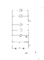
Fig. 6 is correspondent control circuits figure.
Fig. 7 is a rotating cylinder slide plate working state schematic representation.
Air supply system comprises electric air compressor 1, votage control switch 4, air intake valve 6, suction tude 5, gas receiver 7, air supply pipe 8, air-supplying valve 9 and starting valve 12 etc.Electric air compressor is drawn into air from atmosphere.By filter cleaner 2, isolate dry air by oil and water seperator 3 after compression earlier, send into gas receiver by suction tude and air intake valve.Gas receiver is by air supply pipe, air-supplying valve, oil sprayer 10 and tee union
 Deliver to the
 suction port 20 and 33 that rotating cylinder 13 and gear promote cylinder 32 respectively.Air compressor, gas receiver and pipeline, the valve of original brake usefulness on the vehicle be can utilize, a starting valve and tee union installed again additional.Air compressor is by votage control switch 52 controls.
Power mechanism is a rotating cylinder 13, and the internal diameter of cylinder is 16cm, cylindrical cylinder body 14, and length is 20cm.Rotor 15 is arranged in the cylinder, and its diameter is 12cm.Slide plate groove 17 is arranged with the rotor dimidiation in the rotor, slide plate 18 is housed in the groove, it is wide to be 0.6cm, long for 20cm, very little with the gap of slide plate groove, seals under the cooperation of lubricant oil.Between two slide plates, four sliding blade springs 19 are housed, in rotor so that eject slide plate and cylinder wall close contact.
Rotor is connected at two ends by two semicylinders and end cap 55 and rotor shaft 16 and forms.In cylinder, the gap between cylinder wall and rotor is very little, under the cooperation of lubricant oil, can guarantee good seal.Rotor is fixed on the interior bearing 28 and 30 of cylinder, and band seal ring 29.Rotor shaft is provided with driving gear 44, and it and rotor shaft adopt the spline fitted mode, are made up of two-part, and one is a gear, meshes in order to the flywheel 57 with internal-combustion engine 50, with transferring power; It two is the middle cylindrical body that has ring-type shift fork groove 41, and both are connected as a single entity.The shift fork groove engages with shift fork 49, is convenient to shift fork and stirs driving gear.Driving gear can move axially in the rotor shaft upper edge, but can not rotate around rotor shaft.Rotor shaft is fixed on the bearing 31, and bearing 31 is fixed on the rotary cylinder body.
Provide power by rotary cylinder.Pressurized air is blown into by suction port 20, promotes slide plate, produces moment.By the rotor shaft outputting power.As shown in Figure 7, when rotor sliding-vane is in any position, all be compressed the effect of air.Its moment variations is little shown in (f) among Fig. 7.
Can learn that by Fig. 7 when slide plate was in the position of (b), slide plate stretched out the height maximum of rotor.Therefore, bear the area maximum of pressure.And force bearing point is also far away apart from rotor axis.Therefore, at this moment rotor gained moment maximum is approximately 38Kgm.When slide plate was in (C) position, the moment of rotor gained was less, is approximately 15Kgm.
If the gear ratio of driving gear and internal combustion engine flywheel gear is 4: 1, so, available moment is 60~150Kgm on I. C. engine crankshaft.It is 10~20Kgm that this internal-combustion engine requires starting torque.If start while starting to walk, then requiring is 40~50Kgm.From the above, this starter motor can be satisfied the demand.
Internal-combustion engine rotational speed is 200T/Min during starting, and then the rotor speed of rotary cylinder is 800T/Min.Air consumption is 0.6m
2/ Min.The arrangement total capacity is 0.6m
2Gas receiver.Only need about about 5 seconds, the not enough 0.1m of air consumption during general engine starting
2
The rotary cylinder rotor is during with the rotational speed of 800T/Min, and the maximum line velocity at slide plate top is about
 3m/sec, the speed of piston ring in cylinder in the general internal-combustion engine, its wearing and tearing are little.The Sliding velocity of slide plate in vane slot is extremely low, and its wearing and tearing are very little.Because rotating speed is low, the operating time is short, and under the cooperation of lubricant oil, the sealing between each parts is accomplished easily.In the running, pressurized air constantly expands, and temperature cylinder is reduced, so each parts needn't be considered heat radiation in this cylinder, and lubricant oil viscosity when temperature is low increases, and has strengthened sealing.Oil pump only just injects lubricant oil when rotary cylinder is worked, the oil pressure of injection is slightly larger than compressed air pressure, can inject smoothly.
If the increasing compressed air pressure then can reduce the size of gas receiver.For example, compressed air pressure is enlarged to 12Kg/cm
2Then the size of gas receiver can be reduced to original half, and the size of two cylinders also can reduce greatly.
The row 1 of rotating cylinder is connected with dust-proof cover 27 by outlet pipe 26.Oil hole 22 on the rotating cylinder is connected with oil pump 24 by oil filler pipe 23.
The transmission adopted gear promotes cylinder 32, and cylinder adopts cylindrical, and its internal diameter is 4cm, length is 10cm, and the sealed rubber ring of anti-gas-leak is housed on its cylinder piston 37, and piston rod 38 stretches out outside the cylinder, be provided with seal ring 43 and sleeve 42 in the joint, with anti-gas-leak.Front end at cylinder has suction port 33, just promotes piston backward after pressurized air enters.Cylinder exhaust port 34 links to each other with atmosphere by dust-proof cover 35.
Be connected with shifting fork bar 39 by tip nail 47 on the air cylinder connecting rod, ring washer 46 and rod spring 36 in addition on the connecting rod are used for piston reset.Interlinking lever end is connected with fixed muffle 45.Shifting fork bar rotates around declutch shift shaft 40.48 is driving gearshaft.
Electric switch main switch 51 control air intake valve 6 and air-supplying valve 9 and other circuit 56 in the control circuit, votage control switch 52 control electric air compressors 1, switch starter 53 control starting valve 12 and oil pump 24.Power supply adopts storage battery 54.
Claims (5)
1, a kind of starting arrangement that is mainly used in internal-combustion engine, adopts the pneumatic starting mode, comprise air supply system, power mechanism, driving mechanism and control circuit, air supply system adopts and is filled with compressed-air actuated gas receiver and valve, the gas receiver that it is characterized in that air supply system is connected with electric air compressor by suction tude, air intake valve, is connected with driving mechanism with power mechanism by air supply pipe, air-supplying valve; Said power mechanism adopts rotating cylinder, and the central shaft of cylinder rotary does not overlap with the central shaft of cylinder block but be parallel, and rotor shaft is provided with transmission part and is connected with driving mechanism, internal combustion engine flywheel, and cylinder is provided with suction port and is connected with air supply system; Said driving mechanism adopts gear to promote cylinder, and cylinder piston is connected with transmission part on the rotor shaft by piston rod and shift fork, and cylinder is provided with suction port and is connected with air supply system; Rotating cylinder and gear promote cylinder all has relief opening to communicate with atmosphere.
2, starting arrangement according to claim 1 is characterized in that establishing groove on the rotor of rotating cylinder, and slide plate is housed on the groove, and the slide plate bottom is provided with sliding blade spring, and the top of slide plate contacts with cylinder wall, and rotor is close to cylinder wall.
3, starting arrangement according to claim 1 is characterized in that transmission part with the driving gear that is enclosed within on the rotor shaft, adopts the spline fitted Placement with rotor shaft, and driving gear is provided with the shift fork groove and is connected with shift fork.
4, starting arrangement according to claim 1 is characterized in that the shifting fork bar of shift fork is connected with piston rod by tip nail, and shifting fork bar is fixed on the declutch shift shaft.
5, starting arrangement according to claim 3 is characterized in that the flywheel of driving gear and internal-combustion engine adopts the mode that is connected with a joggle.
Priority Applications (1)
| Application Number | Priority Date | Filing Date | Title |
|---|---|---|---|
| CN 88103356 CN1032694A (en) | 1988-05-30 | 1988-05-30 | Pneumatic starter |
Applications Claiming Priority (1)
| Application Number | Priority Date | Filing Date | Title |
|---|---|---|---|
| CN 88103356 CN1032694A (en) | 1988-05-30 | 1988-05-30 | Pneumatic starter |
Publications (1)
| Publication Number | Publication Date |
|---|---|
| CN1032694A true CN1032694A (en) | 1989-05-03 |
Family
ID=4832561
Family Applications (1)
| Application Number | Title | Priority Date | Filing Date |
|---|---|---|---|
| CN 88103356 Pending CN1032694A (en) | 1988-05-30 | 1988-05-30 | Pneumatic starter |
Country Status (1)
| Country | Link |
|---|---|
| CN (1) | CN1032694A (en) |
Cited By (5)
| Publication number | Priority date | Publication date | Assignee | Title |
|---|---|---|---|---|
| CN101545441B (en) * | 2008-03-27 | 2010-12-08 | 广西玉柴机器股份有限公司 | A gas starting device for an engine |
| CN102261296A (en) * | 2010-05-31 | 2011-11-30 | 三一重型装备有限公司 | Air startup protection device of diesel engine and air startup diesel engine comprising same |
| CN103717876A (en) * | 2011-06-17 | 2014-04-09 | Ge延巴赫两合无限公司 | Method for starting an internal combustion engine |
| CN104271940A (en) * | 2012-05-10 | 2015-01-07 | 瓦锡兰芬兰有限公司 | Pneumatic system for piston engine |
| CN106593655A (en) * | 2016-11-22 | 2017-04-26 | 沈阳黎明航空发动机(集团)有限责任公司 | Air turbo-starter air supplying system and control method |
-
1988
- 1988-05-30 CN CN 88103356 patent/CN1032694A/en active Pending
Cited By (10)
| Publication number | Priority date | Publication date | Assignee | Title |
|---|---|---|---|---|
| CN101545441B (en) * | 2008-03-27 | 2010-12-08 | 广西玉柴机器股份有限公司 | A gas starting device for an engine |
| CN102261296A (en) * | 2010-05-31 | 2011-11-30 | 三一重型装备有限公司 | Air startup protection device of diesel engine and air startup diesel engine comprising same |
| CN102261296B (en) * | 2010-05-31 | 2012-09-26 | 三一重型装备有限公司 | Air startup protection device of diesel engine and air startup diesel engine comprising same |
| CN103717876A (en) * | 2011-06-17 | 2014-04-09 | Ge延巴赫两合无限公司 | Method for starting an internal combustion engine |
| US9316197B2 (en) | 2011-06-17 | 2016-04-19 | Ge Jenbacher Gmbh & Co Ohg | Method for starting an internal combustion engine |
| CN103717876B (en) * | 2011-06-17 | 2016-05-25 | Ge延巴赫两合无限公司 | For the method for cranking internal combustion engine |
| CN104271940A (en) * | 2012-05-10 | 2015-01-07 | 瓦锡兰芬兰有限公司 | Pneumatic system for piston engine |
| CN104271940B (en) * | 2012-05-10 | 2016-06-29 | 瓦锡兰芬兰有限公司 | Pneumatic system for piston-mode motor |
| CN106593655A (en) * | 2016-11-22 | 2017-04-26 | 沈阳黎明航空发动机(集团)有限责任公司 | Air turbo-starter air supplying system and control method |
| CN106593655B (en) * | 2016-11-22 | 2018-07-31 | 沈阳黎明航空发动机(集团)有限责任公司 | Air turbine starter air supply system and control method |
Similar Documents
| Publication | Publication Date | Title |
|---|---|---|
| AP938A (en) | Supercharger installation for supplying high pressure compressed air for cleansed or pollution abating engine. | |
| US6311486B1 (en) | Method for operating a pollution-reducing engine | |
| JP5042298B2 (en) | Internal combustion engine | |
| CN102282347B (en) | rotary piston engine | |
| OA11110A (en) | Method and device for re-acceleration of a vehicle equipped with high-pressure air compressors | |
| US6006519A (en) | Compressed air-powered engine | |
| CN1032694A (en) | Pneumatic starter | |
| CN100412319C (en) | Air engine | |
| RU193641U1 (en) | Rotary air compressor motor with internal combustion engine function | |
| CN113898501A (en) | A high-pressure gas supplement system for diesel vehicle plateau starting | |
| CN2228552Y (en) | Vehicle carried engine hydraulic starter | |
| CN103206251B (en) | Variable multi-cylinder aerodynamic engine | |
| CN1164861C (en) | Direct drive type reciprocating piston IC engine | |
| CN212054817U (en) | A two-stroke compressed air engine, automobile drive system and power generation system | |
| CN1217430A (en) | Air engine | |
| EP2631425A2 (en) | System for adapting an internal combustion engine so that it is operated using compressed air or gas | |
| GB2150225A (en) | Vehicle propelled by compressed gas | |
| CN202914139U (en) | Changeable multi-cylinder aerodynamic engine | |
| CN202851086U (en) | Control mechanism for variable multi-cylinder aerodynamic engine | |
| CN115387919B (en) | Oil-gas dual-fuel switching method of marine engine | |
| CN103206252B (en) | The control mechanism of variable multi-cylinder aerodynamic engine | |
| CN1843794A (en) | Automobile power system using compressed air as power | |
| CN2583388Y (en) | Double-rotor pneumatic motor | |
| KR830000842B1 (en) | Starter of air compression 4-stroke internal combustion engine | |
| KR830000843B1 (en) | Method for starting an air compressing four storke internal combustion engine |
Legal Events
| Date | Code | Title | Description |
|---|---|---|---|
| C06 | Publication | ||
| PB01 | Publication | ||
| C01 | Deemed withdrawal of patent application (patent law 1993) | ||
| WD01 | Invention patent application deemed withdrawn after publication |