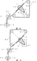
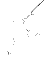
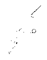
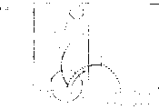
Describe referring now to the developing mechanism of accompanying drawing to the emulsion side by selecting sensitive paper. Fig. 1 is the profilograph of apparatus for photographic development development section of the present invention, and Fig. 2 is its cross section Figure. 3 is paper among the figure, roller centered by 10, and 81 are dishwashing, and 82 is treatment trough, and 83 is nozzle, 84 is circulation port, makes the developer solution of discharging from circulation port 84 from being arranged in the dishwashing 81 The hole of nozzle 83 is sprinkled upon on the breast roll 10, contacts with paper 3 after spreading, and shines to scheme to improve Tablet quality and elimination are developed unequal. Such mechanism and many drive access are used in combination The time, though for emulsion no matter be attached on which face of sensitive paper, can be by selecting operation Develop.
To selecting emulsion side, the drying device that carries out the blowing hot-air switching carries out referring now to accompanying drawing Explanation. Fig. 3-5 is the figure of expression apparatus for photographic development drying section one example of the present invention, and Fig. 3 is Profile from the side, the profile of Fig. 4 for seeing from the top, Fig. 5 is front view. Figure In, 91 is Sirocco fan, and 93 is air door, and 103 is passage slit, and 95,96 is passage, 97 Be feed belt, 98 is heater assembly. Make the hot blast that comes from Sirocco fan pass through air door 93 conversion and change direction, from about in pipeline 95 or 96, be blown into, by as among the figure Like that, hot blast is sent in pipeline 95 or 96 shown in the arrow, used from passage slit 103 Thereby hot blast make the paper drying while paper being abutted in move on the conveyer belt 97.
Because photo and the three-dimensional stereo photo emulsion side when exposure becomes reciprocal shape usually Therefore attitude is necessary to switch the blowing hot-air direction, opens air door, and make along the direction of arrow and move, Just can make hot air flow on the contrary.
Fig. 6-8 is the figure of expression another example of apparatus for photographic development drying section of the present invention, Fig. 6 Be profile from the side, the profile of Fig. 7 for seeing from the top, Fig. 8 is front view. Figure In, 91,92 is western Lip river light fan, and 95,96 is passage, and 98 is unit heater, and 103 are pipe Hole, slit, road by the switching of Sirocco fan 91,92, just can change common photo and three The blowing hot-air direction of dimension stereoscopic photograph.
Fig. 9-11 is expression another illustration of apparatus for photographic development drying section of the present invention, and Fig. 9 is The profile of seeing from the side, Figure 11 are front view, the profile of Figure 10 for seeing from the top, 91,92 is Sirocco fan among the figure, and 95,96 is pipeline, and 98,99 is unit heater, 103 Be the duct slot lyriform pore. The blowing hot-air mechanism of common photo and three-dimensional stereo photo is resembled be divided into the right side Sirocco fan 91 and unit heater 98 and left Sirocco fan 92 and unit heater 99 separate like that fully, from about be blown into hot blast to pipeline 95 or 96.
Figure 12-14 is another illustration of expression apparatus for photographic development drying section of the present invention, figure 12 is the profile of seeing from the side, the figure of Figure 13 for seeing from the top, and Figure 14 is front view. 91 is Sirocco fan among the figure, and 93 is air door, and 95,96 is pipeline, and 97 is conveyer belt, and 98 are Unit heater, 103 is the duct slot lyriform pore. By the switching of air door 93, can come westerly Lip river gram The hot blast direction of fan 91 changes, is blown in pipeline 95 or 96 from the one-sided of dishwashing, An occasion that is blown into hot blast in pipeline 95 or 96, the switching by air door 93 makes A suction inlet of being connected with Sirocco fan connects. Suck hot blast from duct slot lyriform pore 103, Can improve the tensile force of paper on feed belt 97.
Figure 15-the 17th represents the another illustration of print development drying section of the present invention, Figure 15 be from The profile that the side is seen, Figure 16 are the figure that sees from the top, and Figure 17 is front view. Among the figure 91, The 92nd, Sirocco fan, 94 is air door, and 95,96 is pipeline, and 97 is conveyer belt, and 98,99 are Unit heater. The hot blast that blows out from west gram fan 91 is blown into pipeline 95, from Sirocco fan 92 warm-air pipes that blow out are blown into pipeline 96. Owing to blow out hot blast from pipeline on one side, again from other Pipeline sucks hot blast on one side, can improve the tensile force to feed belt of paper. By making air door 94 press the direction of arrow and oblique line part alternating movement in the drawings among the figure, can make hot air flow to Change, be divided into and blow out side and suction side. (air door of reverse side too).
Except possessing the machine of selecting like that as mentioned above emulsion side at development treatment section, drying section Beyond the structure, also possess after exposure, make selectively the mechanism of photographic paper counter-rotating, can energy Satisfy both requirements. Below, describe with reference to the reversing device of accompanying drawing to photographic paper.
Figure 18, the 19th, the figure of paper reversing device one example of expression apparatus for photographic development of the present invention. Figure 18 is that paper is the nonreversible situation of 2D, and Figure 19 is that paper is the situation of three-dimensional counter-rotating. Among the figure 3 is paper, and 11,12 is driven roller, and 21,22 is crimping roller, and 31 is the paper guiding parts, and 41 for driving Moving motor, 51 for driving belt, and 52 is driving wheel, and 60 is conveyer belt, and 80 is exposure desk.
As shown in Figure 18, when the paper that transmits when the travelling belt 60 with exposure desk 80 is generally 2D, then directly is tilted to the lower left and transmits, enter the paper guiding parts, transmit, send from paper guiding parts 31 by driven roller 11,12 and crimping roller 21,22.
As shown in Figure 19, when the paper that transmits when the travelling belt 60 with exposure desk 80 is three-dimensional, by driving motor 41, turning power is sent on the driving wheel 52 through driving belt 51, exposure desk 80 makes the face of paper around 180 ° of center steerings.When beginning paper to be transmitted from this state, and by driven roller 11,12 and crimping roller 21,22, when paper guiding parts 31 is emitted paper 3, then opposite in the table of paper towards paper guiding parts 31.
Figure 20, the 21st, other examples figure of paper reversing device of expression apparatus for photographic development of the present invention, Figure 20 represents that paper is 2D and nonreversible situation, Figure 21 represents that paper is situation three-dimensional and counter-rotating.Symbol among the figure is, 3 is paper, and 77 are suction pump, and 11,12 is driven roller, and 21,22 is crimping roller, and 31,32 is the paper guiding parts, and 60 is travelling belt, and 66 is vertical struts, and 67 is horizontal strut, and 78 is vacuum tube, and 79 is sucker, and 80 is exposure desk.
As shown in figure 20, the paper that transmits when the travelling belt 60 with exposure desk 80 then directly is tilted to the lower left and transmits when being 2D, enter paper guiding parts 31, sending driven roller 11 and crimping roller 21 to enters in next paper guiding parts 32, and send driven roller 12 and crimping roller 22 to, send from paper guiding parts 32 then.
As shown in figure 21, when the paper that transmits when the travelling belt 60 with exposure desk 80 is three-dimensional, through suction pump 77, vacuum tube 78, vertical struts 66, with horizontal strut 67, after making sucker 79 paper absorption, horizontal strut 67 is rotated, and makes the inside out of paper 3, by the action of vertical struts 66, paper 3 is placed on the travelling belt 60.When the suction that cuts off sucker 79, and when paper 3 being tilted to the upper right side transmission, make vertical struts 66 turn back to the origin-location here, by travelling belt 60.When paper 3 being tilted to the lower left transmission by travelling belt 60, just enter paper guiding parts 31, give driven roller 11 and crimping roller 21, enter next paper guiding parts 32, rely on driven roller 12 and crimping roller 22 to transmit,, make in the table of paper opposite when making paper 3 when paper guiding parts 32 is sent.
Figure 22, the 23rd, the figure of another structure example of the paper reversing device of expression apparatus for photographic development of the present invention.Figure 22 represents that paper is 2D and nonreversible occasion, and Figure 23 represents that paper is occasion three-dimensional and counter-rotating.3 expression paper among the figure, 13,14 is driven roller.21,22,23,24 is crimping roller, and 31 is the paper guiding parts, and 60 is travelling belt, and 68 is connecting link, and 65 is head roll, and 80 is exposure desk.
As shown in figure 22, when the paper 3 of travelling belt 60 transmission of passing through exposure desk 80 is 2D, transmit as the crow flies by head roll 65 and crimping roller 21, and enter paper guiding parts 31, driven roller 13 and crimping roller 23 are further transmitted, and, seen off from paper guiding parts 31 through driven roller 14 and crimping roller 24.
As shown in figure 23, when the paper 3 of travelling belt 60 transmission of passing through exposure desk 80 is three-dimensional, in the place that head roll 65 and crimping roller 21 are clamped paper 3 tops, making paper 3 is that the center is turned round with connecting link 68 with the roller of head roll 65, surpass crimping roller 22, until the top of paper 3 is sent to travelling belt 60 in face of.The rear end of paper was crimped roller 22 and clipped this moment, when make head roll 65 from then on state reverse, enter in the paper guiding parts 31 from the inlet port of vertical direction with regard to making paper 3, transmit by driven roller 13,14 and crimping roller 23,24, when paper guiding parts 31 is sent paper, make the table the inside of paper reciprocal.
Figure 24, the 25th, another illustration of the paper reversing device of expression apparatus for photographic development of the present invention.Figure 24 represents that paper is 2D and nonreversible occasion, when Figure 25 represents that paper is three-dimensional and the occasion of counter-rotating.11,12,13 is driven roller in the symbol among the figure, and 19 is the processor roller, 33 is the export orientation parts, and 34 is pilot unit, and 35 is the straight-line guidance parts, and 36 are processor inlet guiding parts, 37 is the bend guiding parts, and 60 is travelling belt, and 80 is exposure desk, and 104 is sensor.
As shown in figure 24, when the travelling belt 60 with exposure desk 80 transmits 2D paper, make its driven roller 11,, rely on driven roller 13 to transmit, and transfer to processor roller 19 to processor inlet guiding parts 36 by straight-line guidance parts 35 through export orientation parts 33.
As shown in figure 25, when the paper that transmits when the travelling belt 60 with exposure desk 80 is three-dimensional, make by pilot unit 34 is moved the paper importing bend guiding parts 37 that sends with driven roller 11.Be conveyed into the paper of bend guiding parts 37 and then introduce to the bend guiding parts is inner with driven roller 12.The rear end one of paper surpasses processor 104, and driven roller 11,12 just stops.By driven roller 12 counter-rotatings, paper seen, deliver to till the driven roller 13,, be inserted in the processor inlet guiding parts 36 at the state of paper in counter-rotating thereafter.
Figure 26, the 27th, another illustration of paper reversing device of expression apparatus for photographic development of the present invention, Figure 26 represent that paper is 2D and the occasion that need not reverse, Figure 27 represents that paper is occasion three-dimensional and counter-rotating.11 is driven roller in the symbol among the figure, and 19 is the processor roller, and 33 is the export orientation parts, and 36 is travelling belt, and 80 is exposure desk, and 104 is sensor.
As shown in figure 26,, then directly enter in the export orientation parts 33, transmit downwards again, enter in the processor inlet guiding parts 36, and transfer to processor roller 19 with driven roller when when the travelling belt 60 of exposure desk 80 is sent 2D paper.
As shown in figure 27, when three-dimensional paper when the travelling belt 60 of exposure desk 80 transmits, then enter in the export orientation parts 33, transmit downwards with driven roller 11, when the top of detecting paper delivery with processor, then driven roller 11 stops again, under the state that keeps paper, stop, motor with reciprocating movement revolution under this state makes 180 ° of outlet guiding parts 33 revolutions, and makes the paper counter-rotating.Under the state of counter-rotating, make driven roller 11 counter-rotatings, and principal direction processor inlet guiding parts 36 is transmitted.
In order to solve the problem of 2D and three-dimensional different disposal time, the transmission route of common photo and 3 D stereo photo is switched.Describe referring now to the switching mechanism of accompanying drawing the transmission route of development section sensitized paper.
Figure 28 is the sectional view of expression apparatus for photographic development development section one example of the present invention, and Figure 30 represents its lever portion, and Figure 29 is that it transmits route model figure.Symbol among the figure is, 38,39 is guiding parts, and 85 for striding frame, and 86 is suspension rod, and 87 is solenoid.When paper is three-dimensional,, presses route shown in the arrow and turn, and send N01 → N02 to and stride frame along the guiding parts that is in 39 positions.When paper is 2D, suspension rod 86 is risen to dotted line position, makes guiding parts move to 38 position with solenoid 87, make paper along route is straight pass through after, make to N03 and transmit through striding frame 85.Can compensate the needed mistiming of development treatment with this mechanism.
Figure 31 is the sectional view of another structure example of expression apparatus for photographic development development section of the present invention, and Figure 32 is its side profile figure.Symbol 38,39 among the figure is a guiding parts, and 47 is motor, and 61-63 is gear, when paper is three-dimensional, makes it press route shown in the arrow along the guiding parts that is in 39 positions and turns, and sends N01 → N02 to and strides frame.When paper is 2D, make gear 61-63 revolution with motor 47, by transmitting to 61,62 and 63, guiding parts is moved to 38 position, make paper along route is straight pass through after, cross over the same with above-mentioned example transmitted to N03 via striding frame.
Figure 33 is expression apparatus for photographic development development section of the present invention another routine sectional view, is to replace Figure 31 with the power that chain or belt 64 transmit motor 47, is used for the gear that example adopts shown in 32.
Figure 34 is another routine sectional view of expression apparatus for photographic development development section of the present invention, and Figure 35 is its side profile figure.Symbol among the figure is 25,26,27,28,29 and 30 for roller, 88 for 2D paper with transmitting the road, 89 be that three-dimensional paper is used the transmission road.Be divided into 2D with 88 and three Wesys 89 transmitting a road, and form striding on the frame of one, owing to be divided into route by 25-27-28-26, give 2D that N01 → N02 strides frame with transmitting road 88 and by 25-29-30-26 route, give N01 → N02 → N03, three Wesys of striding frame transmit road 89, therefore, and can the topped different processing time.
Lens in order to make the print of 3 D stereo photo the time move, and three-dimensional lens, 2D lens are arranged on the supporting plate that possesses travel mechanism, and the switching by to common photo print and the print of 3 D stereo photo can realize the photo angle of wishing.Below, with reference to accompanying drawing lens moving mechanism is described.
Figure 36 is the figure of expression apparatus for photographic development lens moving mechanism one example of the present invention, symbol among the figure is, 7 is the negative film monitoring camera, and 8 are the 2D lens, and 9 is three Wesy's lens, 46 is motor, 48 is 2D lens supporting plates, and 49 is the three-dimensional lens plate, and 58 is fixed frame, 59 for sending screw rod to, and 69 is rectilinear orbit.
Three-dimensional lens 9 and negative film monitoring camera 7 are arranged on the three-dimensional lens supporting plate, three-dimensional lens supporting plate 49 is arranged on the linear track 69, with the fixed frame 58 fixing screw rods 59 that transmit.In addition, 2D lens 8 are arranged on the 2D lens supporting plate 48.When using the 2D lens, the fixing use on assigned position.When using the 2D lens,, make the three-dimensional lens supporting plate make a concession dotted line position among the figure with transmission screw rod 59 according to the revolution of motor 46.When using three-dimensional lens, then moving three dimension lens supporting plate carries out print, so that the photo angle that obtains wishing.
Figure 37 is other routine key diagrams of the lens moving mechanism of expression apparatus for photographic development of the present invention.Symbol among the figure is, 7 is monitoring camera, and 8 is the 2D lens, and 9 is three-dimensional lens, and 46 is motor, and 48 is 2D lens supporting plates, and 49 is the three-dimensional lens supporting plate, and 53 is feed belt, and 58 is fixed frame, and 69 is rectilinear orbit.
Three-dimensional lens 9 and monitoring camera 7 are arranged on the three-dimensional lens supporting plate 49, and three-dimensional lens supporting plate 49 is placed on the rectilinear orbit 69, uses fixedly feed belt 53 of fixed frame 58.In addition, 2D lens 8 are arranged on the 2D lens supporting plate 48.When using the 2D lens board, the fixing use according to the revolution of motor 46, makes the three-dimensional lens supporting plate make a concession dotted line position among the figure with feed belt 53 when using the 2D lens on assigned position.When using three-dimensional lens, the moving three dimension lens carry out print, so that the photo angle that obtains wishing.
Figure 38 is another routine key diagram of the lens moving mechanism of expression apparatus for photographic development of the present invention.Symbol among the figure is, 7 is monitoring camera, and 8 is the 2D lens, and 9 is three-dimensional lens, and 46 is motor, and 48 is 2D lens supporting plates, and 49 is the three-dimensional lens supporting plate, and 54 is rack-and-pinion, and 69 is rectilinear orbit.
Three-dimensional lens 9 and monitoring camera 7 are arranged on the three-dimensional lens supporting plate 49, three-dimensional lens supporting plate 49 is placed on the rectilinear orbit 69, is used in the transmission tooth that forms on one side of three-dimensional lens supporting plate 49 and passes through motor 46 rotating gears to constitute rack-and-pinions 54.In addition, when using 2D lens supporting plate, in the fixing use of assigned position.When using the 2D lens, with the power of motor 46 rack-and-pinion 54 is moved, make the three-dimensional lens supporting plate make a concession dotted line position among the figure.When using three-dimensional lens, move the three-dimensional lens supporting plate and carry out print, so that the photo angle that obtains wishing.
Figure 39 is another routine key diagram of the lens moving mechanism of apparatus for photographic development of the present invention.Symbol among the figure is, 7 is monitoring camera, and 8 is the 2D lens, and 9 is three-dimensional lens, and 46 is motor, and 48 is 2D lens supporting plates, and 49 is the three-dimensional lens supporting plate, and 55 is movement arm, and 58 is fixed frame, and 69 is rectilinear orbit.
Three-dimensional lens 9 and monitoring camera are provided with on the three-dimensional lens supporting plate.Three-dimensional lens supporting plate 49 is placed on the rectilinear orbit 69, in order to have sliding, makes to be fixed on movement arm 55 on the motor 46 by revolving shaft and to be connected on a jiao of three-dimensional lens supporting plate 49.The 2D lens are arranged on the 2D lens supporting plate 48.When using 2D lens supporting plate, in the fixing use of assigned position.When using the 2D lens, making movement arm 55 by the power with motor 46 is that the center is turned round with its revolving shaft, makes the three-dimensional lens supporting plate make a concession dotted line position among the figure.When using three-dimensional lens, moving three dimension lens supporting plate carries out print so that the photo angle that obtains wishing.
Now to the occasion at employing absorption type exposure desk, the mechanism that changes its absorption affinity in common photo and 3 D stereo photo remarks additionally in the following order.
Figure 40 is the sectional view that expression absorption type exposure desk is constructed an example.Symbol among the figure is, 44 for transmitting motor, and 56 be engaged wheel, and 57 be driving wheel, and 60 is travelling belt, and 71 is adsorption plate, and 72 is adsorption box, and 73 is to adsorb fan, and 74 is pipeline.This routine exposure desk is constructed, and on 56 open wide cut travelling belts 60 of driving wheel 57 principal and subordinate wheels a plurality of apertures is set, and the suction that produces with absorption fan 73 passes through this aperture, and paper is adsorbed.Keep the planarity of the exposed portion of travelling belts 60 with adsorption plate 71, adsorption box 72 is the suction of absorption fan to be distributed along exposure desk comprehensively open, and 74 for connecting its both pipeline.
(1) of Figure 41-(4) are the illustratons of model that expression absorption type exposure desk paper transmits an example.Symbol among the figure is, 4 is paper bowl, and 15 is outlet roller, and 20 is driven roller, and 60 is travelling belt, and 70 is sliding axle, and 80 is exposure desk, and 110 is stapling machine.Beginning, (1) waits for the top of paper on stapling machine, stop.(2), be transmitted band on one side thereafter and adsorb, Yi Bian stop when being sent to exposure position when driven roller 20 revolution, when paper only is transmitted specified length, paper is cut off in stapling machine 110 actions.(3) on this position,, whole exposure desk 80 1 edge sliding axles 70 expose Yi Bian being moved.(4) behind the end exposure, be sent to outlet roller 15 with travelling belt 60 once more.
After paper is cut off machine and cuts into specified length, be attracted on the travelling belt, and be transferred into exposure position with the driving that transmits motor.As end exposure, make once more and transmit the motor revolution, principal direction is gone out roller transmit.This exposure desk need change absorption affinity according to photographic paper thickness.In order to change absorption affinity, can consider to change the voltage of the absorption fan that produces absorption affinity, perhaps change the mechanism of air mass flow etc.
Followingly describe with reference to the absorption affinity changeable mechanism of accompanying drawing to such absorption type exposure desk.Figure 42 is the sectional view of expression apparatus for photographic development absorption type exposure desk absorption affinity changeable mechanism one example of the present invention.Symbol among the figure is, 1 is power supply unit, and 73 are the absorption fan, and 75 be adsorption plane, and 76 for adsorbing flexible pipe, and 80 is exposure desk.The absorption affinity that is produced by absorption fan 73 acts on by absorption flexible pipe 76 on numerous aperture on the adsorption plane 75 of exposure desk 80.By changing the voltage that the power supply unit 1 of electric power is provided to absorption fan 73, absorption affinity is changed.
Figure 43 is the sectional view of another structure example of expression apparatus for photographic development absorption type exposure desk suction changeable mechanism of the present invention.Symbol 75 among the figure is an adsorption plane, and 76 are the absorption flexible pipe, and 80 is exposure desk, and 105 is the air quantity control panel, and 62 are air quantity control solenoid.Need the occasion of strong absorption affinity at paper, air quantity control solenoid 62 is connected, mobile air quantity control panel makes circulation area become big.When the needs absorption affinity dies down, then turn-off air quantity compensation solenoid, the air quantity compensating plate is on the original position, flow path is controlled.Present embodiment is the air flow circuit area by changing absorption affinity, changes absorption affinity.
Figure 44 is the sectional view of the another example of expression apparatus for photographic development absorption type exposure desk absorption affinity changeable mechanism of the present invention, Figure 45 is a solenoid side enlarged drawing, symbol among the figure is, 72 is adsorption box, 75 is adsorption plane, and 76 are the absorption flexible pipe, and 107 is solenoid, 108 is the solenoid operation strip, and 109 is airtight member.
In the strong absorption affinity occasion of needs, make solenoid 107 disconnect 108 one-tenth free states of solenoid operation strip.The negative pressure that produces in adsorption box 72 by the absorption fan makes 108 absorption of solenoid operation strip, and adsorption box 72 is airtight.For absorption affinity is died down, connect solenoid 107.Because solenoidal operation strip 108 is fixed on the solenoid 107, the hole of adsorption box 72 in opened condition, negative pressure surpasses to a certain degree in the case, thereby absorption affinity is suppressed.Present embodiment lowers the negative pressure in the adsorption box with regard to the on-off action of tight tired spool and absorption affinity is suppressed and the mechanism that changes.
Below the mechanism that 3 D stereo photo processing power is improved is described.By exposure desk can be moved, form to make and also can be separated into route more than 2 by the paper of from the paper bowl to the driven roller, supplying with.In development treatment, to compare with common photo, the processing speed when forming the 3 D stereo photo is slack-off, yet by paper being separated into the route more than 2, processing power is improved.
In addition, for do not contact the photographic paper the inside that is positioned at common photo in the mark lettering, form groove on the part admittedly at the circle of the roller of exposure desk etc., lettering and roll surface are not joined.Yet the groove of this roller circumferential section will contact with the emulsion side of sensitized paper when carrying out the processing of 3 D stereo photo, probably can influence the 3 D stereo photographic quality.In the present invention, be the moving exposure platform, avoid the groove on the roller, so that make the paper that send the 3 D stereo photo.
Figure 46 is the figure that in the fort that exposes to the sun of apparatus for photographic development of the present invention an example that makes the processing route change is described.Among the figure, 16 do not insert roller, and 17 is transfer roller, and 45 is motor, and 50 is mobile screw, and 58 is fixed block, and 60 is travelling belt, and 70 is shifting axle, and 80 is exposure desk.
Exposure desk 80 is set on the shifting axle 70 by travelling belt 60, and fixes with mobile screw 50 and fixed block 58.From inserting roller 16 principal direction that is sent direction B transmission, send through transfer roller 17.In addition, exposure desk can move along direction A, and paper is moved along position shown in the dot-and-dash line among the figure, is divided into 2 above routes and sends.
Owing to also can go out paper by several dispatch in this way, expose so can change the position of exposure desk 1.When processor transmits, owing to utilize the mobile of this exposure desk to be divided into two row's transmission, so can prevent the decline of 3 D stereo photo processing power.
In addition, as common photo, for the mark lettering of the inside of avoiding influencing photographic quality and be provided with and be arranged in the such groove in figure transfer roller 17 fronts.Yet for the 3 D stereo photo, this groove will damage emulsion side, influence photographic quality.In occasion of the present invention, owing to can transmit paper by the groove that exposure desk is moved avoid on this roller, so can not reduce the 3 D stereo photographic quality.Be to use mobile screw that exposure desk is moved in the present embodiment, thereby also can be adapted to belt mode or tooth bar and pinion wheel mode, also can replace shifting axle with rectilinear orbit.