CN103299539A - Power conversion apparatus - Google Patents
Power conversion apparatus Download PDFInfo
- Publication number
- CN103299539A CN103299539A CN2011800650625A CN201180065062A CN103299539A CN 103299539 A CN103299539 A CN 103299539A CN 2011800650625 A CN2011800650625 A CN 2011800650625A CN 201180065062 A CN201180065062 A CN 201180065062A CN 103299539 A CN103299539 A CN 103299539A
- Authority
- CN
- China
- Prior art keywords
- torque
- motor
- peak
- value
- power
- Prior art date
- Legal status (The legal status is an assumption and is not a legal conclusion. Google has not performed a legal analysis and makes no representation as to the accuracy of the status listed.)
- Granted
Links
Images


Classifications
-
- H—ELECTRICITY
- H02—GENERATION; CONVERSION OR DISTRIBUTION OF ELECTRIC POWER
- H02M—APPARATUS FOR CONVERSION BETWEEN AC AND AC, BETWEEN AC AND DC, OR BETWEEN DC AND DC, AND FOR USE WITH MAINS OR SIMILAR POWER SUPPLY SYSTEMS; CONVERSION OF DC OR AC INPUT POWER INTO SURGE OUTPUT POWER; CONTROL OR REGULATION THEREOF
- H02M7/00—Conversion of AC power input into DC power output; Conversion of DC power input into AC power output
- H02M7/42—Conversion of DC power input into AC power output without possibility of reversal
- H02M7/44—Conversion of DC power input into AC power output without possibility of reversal by static converters
- H02M7/48—Conversion of DC power input into AC power output without possibility of reversal by static converters using discharge tubes with control electrode or semiconductor devices with control electrode
-
- H—ELECTRICITY
- H02—GENERATION; CONVERSION OR DISTRIBUTION OF ELECTRIC POWER
- H02P—CONTROL OR REGULATION OF ELECTRIC MOTORS, ELECTRIC GENERATORS OR DYNAMO-ELECTRIC CONVERTERS; CONTROLLING TRANSFORMERS, REACTORS OR CHOKE COILS
- H02P23/00—Arrangements or methods for the control of AC motors characterised by a control method other than vector control
- H02P23/26—Power factor control [PFC]
-
- H—ELECTRICITY
- H02—GENERATION; CONVERSION OR DISTRIBUTION OF ELECTRIC POWER
- H02P—CONTROL OR REGULATION OF ELECTRIC MOTORS, ELECTRIC GENERATORS OR DYNAMO-ELECTRIC CONVERTERS; CONTROLLING TRANSFORMERS, REACTORS OR CHOKE COILS
- H02P27/00—Arrangements or methods for the control of AC motors characterised by the kind of supply voltage
- H02P27/04—Arrangements or methods for the control of AC motors characterised by the kind of supply voltage using variable-frequency supply voltage, e.g. inverter or converter supply voltage
- H02P27/06—Arrangements or methods for the control of AC motors characterised by the kind of supply voltage using variable-frequency supply voltage, e.g. inverter or converter supply voltage using DC to AC converters or inverters
-
- H—ELECTRICITY
- H02—GENERATION; CONVERSION OR DISTRIBUTION OF ELECTRIC POWER
- H02P—CONTROL OR REGULATION OF ELECTRIC MOTORS, ELECTRIC GENERATORS OR DYNAMO-ELECTRIC CONVERTERS; CONTROLLING TRANSFORMERS, REACTORS OR CHOKE COILS
- H02P29/00—Arrangements for regulating or controlling electric motors, appropriate for both AC and DC motors
- H02P29/02—Providing protection against overload without automatic interruption of supply
- H02P29/032—Preventing damage to the motor, e.g. setting individual current limits for different drive conditions
-
- H—ELECTRICITY
- H02—GENERATION; CONVERSION OR DISTRIBUTION OF ELECTRIC POWER
- H02P—CONTROL OR REGULATION OF ELECTRIC MOTORS, ELECTRIC GENERATORS OR DYNAMO-ELECTRIC CONVERTERS; CONTROLLING TRANSFORMERS, REACTORS OR CHOKE COILS
- H02P29/00—Arrangements for regulating or controlling electric motors, appropriate for both AC and DC motors
- H02P29/50—Reduction of harmonics
-
- H—ELECTRICITY
- H02—GENERATION; CONVERSION OR DISTRIBUTION OF ELECTRIC POWER
- H02P—CONTROL OR REGULATION OF ELECTRIC MOTORS, ELECTRIC GENERATORS OR DYNAMO-ELECTRIC CONVERTERS; CONTROLLING TRANSFORMERS, REACTORS OR CHOKE COILS
- H02P6/00—Arrangements for controlling synchronous motors or other dynamo-electric motors using electronic commutation dependent on the rotor position; Electronic commutators therefor
- H02P6/10—Arrangements for controlling torque ripple, e.g. providing reduced torque ripple
-
- H—ELECTRICITY
- H02—GENERATION; CONVERSION OR DISTRIBUTION OF ELECTRIC POWER
- H02P—CONTROL OR REGULATION OF ELECTRIC MOTORS, ELECTRIC GENERATORS OR DYNAMO-ELECTRIC CONVERTERS; CONTROLLING TRANSFORMERS, REACTORS OR CHOKE COILS
- H02P6/00—Arrangements for controlling synchronous motors or other dynamo-electric motors using electronic commutation dependent on the rotor position; Electronic commutators therefor
- H02P6/14—Electronic commutators
- H02P6/16—Circuit arrangements for detecting position
-
- H—ELECTRICITY
- H02—GENERATION; CONVERSION OR DISTRIBUTION OF ELECTRIC POWER
- H02M—APPARATUS FOR CONVERSION BETWEEN AC AND AC, BETWEEN AC AND DC, OR BETWEEN DC AND DC, AND FOR USE WITH MAINS OR SIMILAR POWER SUPPLY SYSTEMS; CONVERSION OF DC OR AC INPUT POWER INTO SURGE OUTPUT POWER; CONTROL OR REGULATION THEREOF
- H02M5/00—Conversion of AC power input into AC power output, e.g. for change of voltage, for change of frequency, for change of number of phases
- H02M5/40—Conversion of AC power input into AC power output, e.g. for change of voltage, for change of frequency, for change of number of phases with intermediate conversion into DC
- H02M5/42—Conversion of AC power input into AC power output, e.g. for change of voltage, for change of frequency, for change of number of phases with intermediate conversion into DC by static converters
- H02M5/44—Conversion of AC power input into AC power output, e.g. for change of voltage, for change of frequency, for change of number of phases with intermediate conversion into DC by static converters using discharge tubes or semiconductor devices to convert the intermediate DC into AC
- H02M5/453—Conversion of AC power input into AC power output, e.g. for change of voltage, for change of frequency, for change of number of phases with intermediate conversion into DC by static converters using discharge tubes or semiconductor devices to convert the intermediate DC into AC using devices of a triode or transistor type requiring continuous application of a control signal
- H02M5/458—Conversion of AC power input into AC power output, e.g. for change of voltage, for change of frequency, for change of number of phases with intermediate conversion into DC by static converters using discharge tubes or semiconductor devices to convert the intermediate DC into AC using devices of a triode or transistor type requiring continuous application of a control signal using semiconductor devices only
Landscapes
- Engineering & Computer Science (AREA)
- Power Engineering (AREA)
- Control Of Ac Motors In General (AREA)
- Inverter Devices (AREA)
- Control Of Motors That Do Not Use Commutators (AREA)
Abstract
Description
技术领域technical field
本发明涉及一种控制马达的功率转换装置。The invention relates to a power conversion device for controlling a motor.
背景技术Background technique
迄今为止,对压缩机等的马达进行控制的功率转换装置已广为人知。Conventionally, power conversion devices that control motors such as compressors have been widely known.
在例如专利文献1中,公开了一种根据压缩机在每旋转一周的过程中负载转矩的脉动,使马达的输出转矩产生变动的功率转换装置。即,例如图18所示,在单缸压缩机中,当活塞每旋转一周时,压缩转矩就会根据其旋转角产生变动,马达的负载转矩也会随之产生脉动。因此,在专利文献1的功率转换装置中,使马达的输出转矩与该负载转矩的脉动同步地产生变动。由此来抑制压缩机运转时产生的振动。For example,
另一方面,在专利文献2中,公开了一种对输出电压进行平滑的电容器的电容极小的功率转换装置。具体而言,该功率转换装置包括:交直流转换电路、与该交直流转换电路并联的直流链部以及具有多个开关元件的直交流转换电路。在交直流转换电路中,交流电源的电源电压被进行全波整流后向直流链部输出。在直流链部上连接有静电电容极小的电容器。具体而言,该电容器仅具有为一般平滑电容器的1/100左右的静电电容。为此,整流后的电压作为未被平滑而产生脉动的直流电压从直流链部输出。直交流转换电路将该直流电压转换为交流电后,将该交流电供向马达以驱动马达。在专利文献2所公开的功率转换装置中,通过如上所述的那样使电容器具有小电容,从而谋求功率转换装置的小型化和低成本化。On the other hand, Patent Document 2 discloses a power conversion device in which a capacitor for smoothing an output voltage has an extremely small capacitance. Specifically, the power conversion device includes: an AC-DC conversion circuit, a DC link connected in parallel with the AC-DC conversion circuit, and a DC-AC conversion circuit with a plurality of switching elements. In the AC-DC conversion circuit, the power supply voltage of the AC power supply is full-wave rectified and then output to the DC link section. A capacitor with an extremely small electrostatic capacitance is connected to the DC link. Specifically, this capacitor has an electrostatic capacitance that is only about 1/100 of that of a general smoothing capacitor. For this reason, the rectified voltage is output from the DC link unit as a DC voltage that is not smoothed but pulsates. After the DC voltage is converted into AC power by the DC-to-AC conversion circuit, the AC power is supplied to the motor to drive the motor. In the power conversion device disclosed in Patent Document 2, the size and cost of the power conversion device are reduced by making the capacitor have a small capacitance as described above.
进而,在专利文献3中公开了对专利文献2所示的电容器的电容较小的功率转换装置进行所述转矩控制的情况。也就是说,若直流链部的电容器的静电电容较小,则向直交流转换电路输出的输出电压也会具有脉动分量。因此,在专利文献3中,使马达的负载转矩的脉动分量和电源电压的输出电压的脉动分量包含在输出转矩中,从而让输出转矩根据马达的负载转矩产生变动,来减小压缩机的振动。Furthermore, Patent Document 3 discloses that the torque control is performed on a power conversion device having a small capacitance of the capacitor shown in Patent Document 2. FIG. That is, if the capacitance of the capacitor in the DC link portion is small, the output voltage output to the DC-AC conversion circuit also has a ripple component. Therefore, in Patent Document 3, the pulsation component of the load torque of the motor and the pulsation component of the output voltage of the power supply voltage are included in the output torque, so that the output torque fluctuates according to the load torque of the motor, and the output torque is reduced. Compressor vibration.
专利文献1:日本公开特许公报特开2005-046000号公报Patent Document 1: Japanese Patent Laid-Open Publication No. 2005-046000
专利文献2:日本公开特许公报特开2002-51589号公报Patent Document 2: Japanese Patent Laid-Open Publication No. 2002-51589
专利文献3:日本专利第4192979号Patent Document 3: Japanese Patent No. 4192979
发明内容Contents of the invention
-发明所要解决的技术问题--The technical problem to be solved by the invention-
在专利文献3所公开的转矩控制工作中,在马达的负载转矩的脉动分量的峰值、与和电源电压同步的直流链电压的脉动分量的峰值相一致的时刻,马达的电流值就会随着输出转矩的增大而增大。为此,随着上述马达的电流值增大,就会出现招致开关元件损坏及马达磁铁退磁的不良现象。作为消除这种不良现象的方法,在例如专利文献3中公开了一种检测马达的电流值,若该电流超过规定的上限值就使输出转矩减小的控制方法。In the torque control operation disclosed in Patent Document 3, when the peak value of the pulsating component of the load torque of the motor coincides with the peak value of the pulsating component of the DC link voltage synchronous with the power supply voltage, the current value of the motor decreases. It increases with the increase of output torque. For this reason, as the electric current value of the above-mentioned motor increases, there are disadvantages such as damage to the switching element and demagnetization of the motor magnet. As a method of solving this problem, for example, Patent Document 3 discloses a control method of detecting a motor current value and reducing the output torque when the current exceeds a predetermined upper limit.
然而,因为直流链电压的脉动分量和负载转矩的脉动分量以互不相同的频率进行脉动,所以两个分量的峰值时刻未必相一致。为此,即便在两者的峰值相偏离的时刻对马达的电流进行检测,该电流值也是比较低的值,因而无法检测出所希望的峰值电流。其结果是,无法准确地限制马达的输出转矩的变动幅度,从而有可能出现上述那样的不良现象。However, since the pulsating component of the DC link voltage and the pulsating component of the load torque pulsate at frequencies different from each other, the peak timings of the two components do not necessarily coincide. For this reason, even if the current of the motor is detected at a time when the peak values of the two are deviated from each other, the current value is relatively low, and thus a desired peak current cannot be detected. As a result, the fluctuation range of the output torque of the motor cannot be accurately limited, and the above-mentioned disadvantages may occur.
本发明正是鉴于所述问题而发明出来的,其目的在于:提供一种在转矩控制工作中能够可靠地检测出马达电流上升的功率转换装置。The present invention was conceived in view of the above problems, and an object of the present invention is to provide a power conversion device capable of reliably detecting a rise in motor current during a torque control operation.
-用以解决技术问题的技术方案--Technical solutions to solve technical problems-
第一方面的发明的特征在于:包括转换部20和控制部40,该转换部20具有多个开关元件Sr、Ss、St、Su、Sv、Sw、Sx、Sy、Sz,并利用所述多个开关元件Sr、Ss、St、Su、Sv、Sw、Sx、Sy、Sz的开关动作将来自交流电源6一侧的电转换为规定频率的交流电后,将该交流电向马达5输出,该控制部40进行转矩控制工作,使得所述马达5的输出转矩包含频率为所述交流电源6的输出电压的频率的整数倍的脉动分量即电源脉动分量,且根据所述马达5的负载转矩变动产生变动,并且该控制部40求出当所述电源脉动分量的峰值时刻与所述负载转矩变动分量的峰值时刻相一致或者近似一致时的峰值电流值,并使所述输出转矩的变动幅度减小,使得该峰值电流值不超过规定的上限值。The invention of the first aspect is characterized in that it includes a
此外,例如在功率转换装置具有直流链部时,这里所说的交流电源6的输出电压也包含直流链部的输出电压(即,包含与交流电源6同步的脉动分量的输出电压)。In addition, for example, when the power conversion device has a DC link unit, the output voltage of the
在第一方面的发明中,控制部40使马达5的输出转矩产生脉动,使得马达5的输出转矩中包含交流电源6的输出电压的脉动分量。控制部40还进行使马达5的输出转矩根据马达5的负载转矩的变动产生变动的转矩控制工作。In the first aspect of the invention, the
第二方面的发明是这样的,在第一方面的发明所涉及的功率转换装置中,其特征在于:所述控制部40包括峰值保持部55和转矩控制量调整部54,该峰值保持部55在规定的判断期间保持所述峰值电流值,若由该峰值保持部55保持的峰值电流值超过规定的上限值,该转矩控制量调整部54就使所述马达5的输出转矩的变动幅度减小。The second aspect of the invention is as follows. In the power conversion device according to the first aspect of the invention, the
在该转矩控制工作中,由于峰值保持部55保持马达5的电流的最大值以作为峰值电流,因而能够可靠地导出马达5的峰值电流。就这一点进行详细的说明。In this torque control operation, since the peak
如上所述,在马达5的负载转矩的峰值时刻与交流电源6的输出电压的峰值时刻相一致时,马达5的电流最大。然而,因为马达5的负载转矩的脉动周期与交流电源6的输出电压的脉动周期不一定相同,所以即使在两者峰值不一致的时刻对马达5的电流进行检测,该电流值也是比较小的值。也就是说,如果不在两者峰值相一致的时刻检测马达5的电流,就无法可靠地导出在转矩控制工作时所能产生的马达5的峰值电流。As described above, when the peak timing of the load torque of the
因此,在本发明中,峰值保持部55在每个规定的判断期间都保持马达5的电流的最大值。由此,在该判断期间,能够在马达5的负载转矩的峰值与电源电压的输出电压的峰值大致相重叠的时刻导出峰值电流。若这样导出的峰值电流超过规定的上限值,转矩控制量调整部54就进行减小马达5的输出转矩的变动幅度的控制。Therefore, in the present invention, the
第三方面的发明是这样的,在第二方面的发明所涉及的功率转换装置中,其特征在于:所述控制部40包括速度指令调整部72,该速度指令调整部72对所述马达5的运转频率fc进行补正,使得在所述峰值保持部55的判断期间当中,所述负载转矩的脉动分量的峰值时刻与所述电源脉动分量的峰值时刻相一致或者近似一致。The third aspect of the invention is as follows. In the power conversion device according to the second aspect of the invention, the
在第三方面的发明中,在峰值保持操作的判断期间,能够利用速度指令调整部72使马达5的负载转矩的峰值时刻与直流链部15的输出电压的峰值时刻相一致或者近似一致。其结果是,在该判断期间能够可靠地导出马达5的峰值电流。In the third aspect of the invention, the speed
第四方面的发明是这样的,在第二或第三方面的发明所涉及的功率转换装置中,其特征在于:所述控制部40包括周期导出部71,该周期导出部71根据所述交流电源6的输出电压的频率和所述马达5的运转频率,导出所述马达5的负载转矩的峰值与所述交流电源6的输出电压的峰值相一致或者近似一致的时刻存在的周期;所述速度指令调整部72对所述马达5的运转频率进行补正,使得由所述周期导出部71导出的周期在所述峰值保持部55的判断期间以下。The fourth aspect of the invention is that, in the power conversion device according to the second or third aspect of the invention, the
在第四方面的发明中,周期导出部71根据交流电源6的输出电压的频率和马达5的运转频率,导出交流电源6的输出电压的峰值时刻与马达5的负载转矩的峰值时刻相一致或者近似一致的周期。速度指令调整部72对马达5的运转频率进行补正,使得按照上述方法导出的周期在峰值保持部55的判断期间以下。其结果是,在该判断期间,使交流电源6的输出电压的峰值时刻与马达5的负载转矩的峰值时刻相一致或者近似一致,从而能够导出峰值电流。In the fourth aspect of the invention, the
第五方面的发明是这样的,在第一方面的发明所涉及的功率转换装置中,其特征在于:所述控制部40推定所述峰值电流值,并使所述马达5的输出转矩的变动幅度减小,使得所推定出的峰值电流值不超过规定的上限值。The invention of
在该结构下,能够经推定求出峰值电流值。With this configuration, the peak current value can be obtained by estimation.
第六方面的发明是这样的,在第一至第五方面中的任一方面的发明所涉及的功率转换装置中,其特征在于:包括交直流转换电路11、直流链部15及直交流转换电路20,该交直流转换电路11对来自所述交流电源6的电压进行整流,该直流链部15具有与所述交直流转换电路11的输出侧并联的电容器16,该直交流转换电路20作为所述转换部,将来自所述直流链部15的输出电压转换为交流电压后,将该交流电压向马达5输出;所述电容器16的电容值被设定为使输入所述直交流转换电路20的输入电压产生较大脉动的值。The sixth aspect of the invention is as follows. In the power conversion device according to any one of the first to fifth aspects of the invention, it is characterized in that it includes an AC-
第六方面的发明所涉及的功率转换装置构成为:电容器16的静电电容极小,并且输入直交流转换电路20的输入电压产生较大的脉动。The power conversion device according to the sixth aspect of the invention is configured such that the capacitance of the
-发明的效果--Effects of the invention-
根据第一方面的发明或第二方面的发明,若马达5的峰值电流超过规定值,就使马达5的输出转矩减小。为此,能够避免马达5的电流值过大而导致开关元件等受到损坏的情况于未然。According to the first invention or the second invention, when the peak current of the
特别是在第二方面的发明中,因为进行在规定的判断期间保持马达5的电流值的峰值保持操作,所以能够导出在负载转矩的峰值时刻与电源电压的峰值时刻相一致或者近似一致的时刻的峰值电流。因此,能够可靠地检测出马达5的电流值上升,从而能够可靠地保护开关元件等。In particular, in the second aspect of the invention, since the peak hold operation is performed to hold the current value of the
特别是在第三方面或第四方面的发明中,对马达5的运转频率进行调整,使得在判断期间内负载转矩的峰值时刻与直流链电压的峰值时刻相一致或者近似一致。因为在一般情况下该运转频率是根据电源频率决定的,所以在例如交流电源6的电源频率偏离所希望的频率(例如50Hz或者60Hz)的情况下,也能够以所希望的周期产生差拍(beat)。例如在微型计算机的时钟产生偏差时,也能够以所希望的周期产生差拍。其结果是,在该判断期间内,能够可靠地导出在负载转矩的峰值与直流链电压的峰值相一致或者近似一致的这一时刻的峰值电流。Especially in the invention of the third or fourth aspect, the operating frequency of the
在第五方面的发明中,很容易就能够求出峰值电流。In the fifth aspect of the invention, the peak current can be obtained easily.
在第六方面的发明中,在电容器的静电电容极小的、所谓的无电容器(capacitorless)型功率转换装置中,能够可靠地检测出马达5的电流值上升,从而能够可靠地保护开关元件等。In the sixth aspect of the invention, in a so-called capacitorless power conversion device in which the capacitance of the capacitor is extremely small, it is possible to reliably detect an increase in the current value of the
附图说明Description of drawings
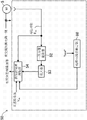
图1是实施方式所涉及的功率转换装置的电路略图。FIG. 1 is a schematic circuit diagram of a power conversion device according to the embodiment.
图2是表示功率转换装置的控制部的具体情况的方框图。FIG. 2 is a block diagram showing details of a control unit of the power conversion device.
图3是表示功率转换装置的转矩控制部的具体情况的方框图。3 is a block diagram showing details of a torque control unit of the power conversion device.
图4是表示在转矩控制工作(转矩控制量=100%)中马达的负载转矩、直流链电压以及马达的输出转矩的波形的曲线图。4 is a graph showing the waveforms of the load torque of the motor, the DC link voltage, and the output torque of the motor in a torque control operation (torque control amount=100%).
图5是表示在转矩控制工作(转矩控制量=150%)中马达的负载转矩、直流链电压以及马达的输出转矩的波形的曲线图,表示的是没用限幅器限制负转矩的状态。Fig. 5 is a graph showing the load torque of the motor, the DC link voltage and the waveform of the output torque of the motor in the torque control operation (torque control amount = 150%), showing that the load torque is not limited by the limiter. state of torque.
图6是表示在转矩控制工作(转矩控制量=150%)中马达的负载转矩、直流链电压以及马达的输出转矩的波形的曲线图,表示的是用限幅器限制了负转矩的状态。Fig. 6 is a graph showing the waveforms of the load torque of the motor, the DC link voltage and the output torque of the motor in the torque control operation (torque control amount = 150%), showing that the load torque of the motor is limited by the limiter. state of torque.
图7是表示在转矩控制工作中马达的负载转矩、直流链电压以及马达的输出转矩的波形的曲线图,表示的是负载转矩的峰值与直流链电压的峰值相一致的状态。7 is a graph showing the waveforms of the load torque of the motor, the DC link voltage, and the output torque of the motor during the torque control operation, showing a state where the peak value of the load torque coincides with the peak value of the DC link voltage.
图8是用以说明在转矩控制工作中峰值保持操作的情况的曲线图。Fig. 8 is a graph for explaining the state of the peak hold operation in the torque control operation.
图9是用以说明马达的负载转矩的峰值与直流链电压的峰值彼此逐渐偏离开的状态的曲线图。9 is a graph for explaining a state where the peak value of the load torque of the motor and the peak value of the DC link voltage gradually deviate from each other.
图10是速度指令补正部的方框图。Fig. 10 is a block diagram of a speed command correction unit.
图11是表示差拍产生的周期与峰值保持操作的判断周期的曲线图,表示的是未在每个判断期间产生差拍的状态。FIG. 11 is a graph showing a cycle of beating generation and a judgment cycle of peak hold operation, showing a state where beating is not generated in each judgment period.
图12是表示速度指令补正部的控制工作情况的流程图。Fig. 12 is a flowchart showing the control operation of the speed command correction unit.
图13是表示差拍产生的周期与峰值保持操作的判断周期的曲线图,表示的是在每个判断期间分别产生差拍的状态。FIG. 13 is a graph showing the cycle of beat generation and the judgment cycle of the peak hold operation, showing the state of beat generation in each judgment period.
图14是表示直流链电压随着电抗器与电容器之间产生的谐振而上升之一例的曲线图。FIG. 14 is a graph showing an example of an increase in DC link voltage due to resonance generated between a reactor and a capacitor.
图15是变形例1所涉及的功率转换装置的电路略图。FIG. 15 is a schematic circuit diagram of a power conversion device according to
图16是变形例2所涉及的功率转换装置的电路图。FIG. 16 is a circuit diagram of a power conversion device according to Modification 2. FIG.
图17是变形例3所涉及的功率转换装置的电路图。FIG. 17 is a circuit diagram of a power conversion device according to Modification 3. FIG.
图18是表示压缩转矩的变动情况之一例的曲线图。FIG. 18 is a graph showing an example of variation in compression torque.
图19是表示本发明第二实施方式所涉及的控制部之结构的方框图。FIG. 19 is a block diagram showing a configuration of a control unit according to a second embodiment of the present invention.
具体实施方式Detailed ways
下面,参照附图对本发明的实施方式进行详细的说明。此外,以下所示的实施方式是本质上优选的示例,并没有意图对本发明、其应用对象或其用途的范围加以限制。Hereinafter, embodiments of the present invention will be described in detail with reference to the drawings. In addition, the embodiment shown below is a preferable example in nature, and it does not intend to limit the scope of this invention, its application object, or its use.
(发明所涉及的第一实施方式)(First Embodiment of the Invention)
本发明所涉及的功率转换装置10与连接在例如空调装置的制冷剂回路中的压缩机的三相交流马达5相连接。压缩机由例如具有一个气缸的旋转式压缩机构成。也就是说,在该压缩机中,当驱动轴旋转一周时,压缩转矩(即,马达5的负载转矩)就产生脉动。马达5是例如4极6槽集中绕组无刷直流马达。如下文所述,在功率转换装置10中构成为:能够进行对该马达5产生的转矩加以控制以抑制马达5振动的转矩控制工作。The
<功率转换装置的整体结构><Overall structure of power conversion device>
如图1所示,功率转换装置10包括:交直流转换电路11、直流链部15、直交流转换电路20以及控制部40。功率转换装置10将由单相交流电源6供给的交流电转换为规定频率的电后供给马达5。As shown in FIG. 1 , the
交直流转换电路11与交流电源6相连接。交直流转换电路11是由多个(在本实施方式中为四个)二极管D1~D4桥式连结而成的、所谓的二极管电桥电路。交直流转换电路11是将交流电源6所输出的交流电经全波整流成直流电的全波整流电路。The AC-
直流链部15与交直流转换电路11的输出一侧并联。电抗器12连接在交直流转换电路11和直流链部15之间。直流链部15具有电容器16。在电容器16的两端产生的直流电压(直流链电压Vdc)与直交流转换电路20的输入节点连接。The DC link
电容器16由例如薄膜电容器构成。电容器16被设定为:该电容器16的静电电容为较小的电容(例如数十μF)。具体而言,电容器16具有:在直交流转换电路20的开关元件Su、Sv、Sw、Sx、Sy、Sz工作时能够对与该开关动作的频率相对应着产生的波纹电压(电压波动)进行平滑的静电电容。另一方面,电容器16具有:无法对已由交直流转换电路11整流过的电压(起因于电源电压的电压波动)进行平滑的静电电容。因此,直流链部15接收交直流转换电路11的输出后,从电容器16的两端输出直流链电压Vdc,该直流链电压Vdc具有频率为交流电源6之电源电压Vin的2倍的脉动。直流链部15输出的直流链电压Vdc具有其最大值在其最小值的2倍以上的较大的脉动。
直交流转换电路20构成转换部,其输入节点与直流链部15的电容器16并联,并经开关切换将直流链部15的输出转换成三相交流电后,供给相连的马达5。本实施方式的直交流转换电路20由多个开关元件桥式连结而成。由于该直交流转换电路20将三相交流电向马达5输出,因而具有六个开关元件Su、Sv、Sw、Sx、Sy、Sz。具体而言,直交流转换电路20包括三个开关桥臂(switching leg),每个开关桥臂由两个开关元件彼此串联而成,在各个开关桥臂中上臂开关元件Su、Sv、Sw与下臂开关元件Sx、Sy、Sz之间的中点分别与马达5的各相中相对应的一相的线圈(省略图示)连接。续流二极管Du、Dv、Dw、Dx、Dy、Dz反并联在各个开关元件Su、Sv、Sw、Sx、Sy、Sz中相对应的一个开关元件上。直交流转换电路20利用这些开关元件Su、Sv、Sw、Sx、Sy、Sz的开关动作,经开关切换将由直流链部15输入的直流链电压Vdc转换成三相交流电压后,供向马达5。The DC-to-
功率转换装置10包括各种检测部。具体而言,功率转换装置10具有:对交流电源6的电源电压Vin进行检测的电源电压检测部25、对交流电源6的电源电压的电源相位θin进行检测的电源相位检测部26以及对交流电源6的电源电压的频率fin进行检测的电源频率检测部27。功率转换装置10还具有对交直流转换电路11的输入电流Iin进行检测的输入电流检测部28、和对直流链部15的直流链电压Vdc进行检测的DC链电压检测部29。进而,功率转换装置10还具有:对流经马达5的电流Idq(具体而言,流经马达5的各相的电流)进行检测的马达电流检测部30、对马达5的相位θm进行检测的马达相位检测部31、以及对马达5的实际旋转速度ωm进行检测的马达转速检测部32。The
控制部40将对直交流转换电路20中的开关(开关动作)进行控制的门信号G向直交流转换电路20输出。本实施方式的控制部40构成为进行下述转矩控制工作,即:使电源电压的脉动分量与马达5的输出转矩合成,并使马达5的输出转矩根据该马达5的负载转矩的变动而产生变动。The
<控制部的具体结构><Specific structure of the control unit>
如图2所示,控制部40包括:速度控制部41、转矩控制部50、转矩控制叠加部42、转矩指令调制部43、二次谐波施加部44、输入电流指令生成部45、放大器46、限幅器60、电流控制部47以及PWM运算部48。As shown in FIG. 2 , the
在减法器34中从马达旋转速度的速度指令ω*中减去马达5的实际旋转速度ωm后得到的差值被输入速度控制部41。速度控制部41通过对实际旋转速度ωm和速度指令ω*之间的差值进行比例积分运算(PI运算),从而算出马达5的负载转矩的平均值(平均转矩)。该平均转矩是以规定周期进行脉动的负载转矩的平均值。速度控制部41将该平均转矩作为指令值(平均转矩指令值Tave *)向转矩控制叠加部42输出。The difference obtained by subtracting the actual rotational speed ω m of the
在转矩控制叠加部42中,平均转矩指令值Tave *与从下文所详细叙述的转矩控制部50中输出的指令值相乘。由此,在转矩控制叠加部42中,就生成了将马达5的负载转矩的脉动分量合成起来的转矩指令值T*。在转矩控制叠加部42中生成的指令值被输入转矩指令调制部43。In the torque control superposition part 42, the average torque command value T ave * is multiplied by the command value output from the
向转矩指令调制部43输入交流电源6的相位角(电源相位θin),该转矩指令调制部43生成正弦值sinθin后,使与该正弦值相对应的调制系数r与转矩指令值T*相乘,并将所得到的结果向二次谐波施加部44输出。二次谐波施加部44对转矩指令调制部43的输出值施加频率为电源频率的2倍的频率分量,使得马达5的输出功率成为正弦波状。所述调制系数r为:例如|sin(θin)|或sin2(θin)。此外,为了使马达5的输出功率接近正弦波,也可以根据电源频率(50Hz或者60Hz)改变调制系数r。还可以根据使相位θin偏移规定量Δ而得到的正弦值sin(θin+Δ)来决定调制系数r,使得马达5的输出功率成为正弦波状。由此,能够获得与施加频率为电源频率的2倍的频率分量几乎相同的效果。The phase angle (power supply phase θ in ) of the
另一方面,输入电流指令生成部45对输入电流Iin进行傅里叶变换,提取出基频分量后,使该基频分量与sin(θin)相乘而生成输入电流的指令值Iin *。在减法器35中,从该指令值Iin *中减去输入电流的绝对值|Iin|后,将所得到的结果向放大器46输出。在放大器46中,相减后所得到的输出值与规定增益相乘。On the other hand, the input
来自二次谐波施加部44的输出值与来自放大器46的输出值在加法器36中相加。相加后所得到的指令值经下文详细叙述的限幅器60加以处理后,输入减法器37。在减法器37中,从由限幅器60一侧输出的指令值中减去实际的马达电流Idq,所得到的值向电流控制部47输出。电流控制部47根据该电流指令值生成电压指令值Vdq *,并将该电压指令值Vdq *向PWM运算部48输出。The output value from the second harmonic applying
PWM运算部48根据电压指令值Vdq *,生成控制各个开关元件Su、Sv、Sw、Sx、Sy、Sz的开关动作的门信号G。由此,各个开关元件Su、Sv、Sw、Sx、Sy、Sz以规定的占空比进行开关动作。The
<转矩控制部的基本结构><Basic structure of the torque control unit>
转矩控制部50用以根据马达5的负载转矩等决定并输出上述转矩指令的控制量。如图3所示,转矩控制部50包括:一次分量提取器52、放大器53、转矩控制量调整部54以及峰值保持部55。The
一次分量提取器52经由傅里叶变换提取出马达5的负载转矩的脉动分量中对马达5的振动产生最大影响的一次分量(基频分量)。放大器53使已由一次分量提取器52提取出的一次分量与规定增益相乘,将相乘所得的结果向转矩控制量调整部54输出。The
转矩控制量调整部54将与上述平均转矩指令值Tave *相乘的指令值作为最终的转矩控制量向所述转矩控制叠加部42输出。为此,从转矩控制叠加部42中输出变动幅度比平均转矩指令值Tave *大的转矩指令值T*。此外,当相乘后所得到的转矩指令值T*的变动幅度与平均转矩指令值Tave *相同时,马达5的输出转矩的变动幅度的大小就相当于负载转矩的平均值(平均转矩),此时输出转矩的变动幅度与平均转矩之比即转矩控制量=100%。在本实施方式中,因为马达5振动的主分量即一次分量大于平均转矩,所以在一般情况下若要进行转矩控制以充分抑制振动的话,转矩控制量就要在100%以上。也就是说,在本实施方式中,当进行转矩控制工作时,马达5的输出转矩被调整为:成为包含比马达5的负载转矩的平均值大的变动幅度之波形。The torque control
图3中所示的峰值保持部55构成:在规定的判断期间保持流经马达5的电流Idq的最大值并导出峰值电流的峰值电流导出部。若该峰值电流超过规定的上限值,转矩控制量调整部54就调整输出指令值以降低转矩控制量。转矩控制量调整部54根据由DC链电压检测部29检测到的直流链电压Vdc对转矩控制量的输出指令值加以限制。The
<关于转矩控制工作的基本工作情况><Basic operation about torque control operation>
对转矩控制工作进行更为具体的说明。上述电流控制部47的输入指令值与用以产生抑制马达5的负载转矩之输出转矩的转矩指令值合成。由此,在进行转矩控制工作时,像例如图4所示的那样对马达5的输出转矩加以控制。此外,图4表示的是在交流电源6的电源频率fin=50Hz、马达5的旋转速度=30rps、转矩控制量=100%的条件下,马达5的负载转矩、从直流链部15输出的直流链电压Vdc以及马达5的输出转矩随时间变化的情况。The torque control operation will be described more concretely. The input command value of the
在本实施方式的功率转换装置10中,直流链电压Vdc以周期Tdc进行脉动,并且马达5的负载转矩以周期Tc进行脉动。为此,输出转矩得到控制,使得交流电源6的电源电压的脉动与负载转矩的脉动合成起来。因此,在例如直流链电压Vdc的峰值与负载转矩的峰值比较接近的时刻,输出转矩也会比较大。由此,因为对马达5的输出转矩进行控制,使得该输出转矩与负载转矩同步,所以马达5的速度变动得到抑制,使得马达5的振动减小。特别是在本实施方式中,因为对马达5的输出转矩进行控制,以抑制成为振动的主要原因之负载转矩的基频分量,所以能够有效地抑制马达5的振动。In the
<关于限幅器><About the limiter>
在上述转矩控制工作中,为了抑制马达5振动的一次分量,转矩控制量要在100%以上。为此,在该转矩控制下,马达5的输出转矩的变动幅度(振幅)很容易变大。因此,若如上所述输出转矩的振幅增大且输出转矩到达负值一侧,马达5就有可能进行再生动作。In the above-mentioned torque control operation, in order to suppress the primary component of vibration of the
具体而言,例如图5所示的示例表示的是在交流电源6的电源频率fin=50Hz、马达5的旋转速度=30rps、转矩控制量=150%的条件下,马达5的负载转矩、从直流链部15输出的直流链电压Vdc以及马达5的输出转矩随时间变化的情况。在该示例中,由于转矩控制量增大而导致输出转矩的变动幅度增大,伴随这一情况,输出转矩就会小于0而变动到负值一侧。其结果是,在图5的用虚线包围起来的区域中,马达5进行再生动作。Specifically, for example, the example shown in FIG. 5 shows the load rotation of the
另一方面,在本实施方式的功率转换装置10中,直流链部15的电容器16的静电电容被设定得极低。为此,若如上所述的那样马达5进行再生动作,则电容器16无法充分地吸收该再生能量而有可能导致直流链部15成为过电压,致使开关元件Su、Sv、Sw、Sx、Sy、Sz等受到损坏。于是,在本实施方式中,如图2所示,通过在控制部40中设置限幅器60,从而对输出转矩成为负转矩加以限制。也就是说,限幅器60根据所输入的指令值生成限制负输出转矩的指令值,以保证马达5的输出转矩不到达负值一侧。由此,例如图6所示,在现有技术下变动到负值一侧的输出转矩(图6中用双点划线所示的输出转矩)维持在处于比负值高的值(例如输出转矩=0)的状态。其结果是,能够可靠地防止马达5的再生动作,从而能够谋求保护开关元件Su、Sv、Sw、Sx、Sy、Sz等。另一方面,在该限幅器60的控制下,对正输出转矩未加任何限制。为此,在转矩控制工作中,能够充分获得马达5的输出转矩,从而能够有效地抑制马达5的振动。On the other hand, in the
此外,在本实施方式中,通过将限幅器60设置在电流控制部47的输入一侧的紧挨着电流控制部47的位置上,从而可靠地防止输出转矩到达负值一侧。然而,只要是将该限幅器60设置在电流控制部47的输入一侧,则也可以将该限幅器60设置在其它位置上。具体而言,还能将该限幅器60设置在转矩控制部50的转矩控制量调整部54的输出一侧。In addition, in the present embodiment, by disposing the
<关于抑制转矩控制工作时马达电流的情况><About suppressing the motor current during torque control operation>
在进行上述转矩控制工作时,由于马达5的输出转矩增大,而导致马达5的电流Idq升高。具体而言,例如图7所示,若马达5的负载转矩的峰值(图7中用双点划线所示的峰值Pl)时刻与直流链电压Vdc的峰值(图7中用白点所示的峰值Pdc)时刻相一致或者近似一致,马达5的输出转矩就会随之变得极大。因此,当上述两者的峰值Pl、Pdc时刻相一致时,马达5的电流就会骤然升高。若如上所述的那样马达5的电流急剧升高,开关元件Su、Sv、Sw、Sx、Sy、Sz的电流值就会超过额定的最大容许电流值,从而会导致开关元件Su、Sv、Sw、Sx、Sy、Sz损坏或者马达5的磁铁退磁。若采用增大器件载流容量的方法作为解决上述问题的对策,就会导致功率转换装置10的成本提高。When the torque control operation described above is performed, the current I dq of the
能够想到的作为解决上述不良现象的对策有:适当地检测马达5的电流值,并对转矩控制量调整部54的转矩控制量加以限制,使得该电流值不超过规定的上限值。然而,在本实施方式中,因为如上所述直流链电压Vdc以规定的频率进行脉动,所以直流链电压Vdc的峰值Pdc时刻与负载转矩的峰值Pl时刻未必相一致(例如参照图4等)。为此,即便在两者的峰值Pdc、Pl偏离开的时刻检测马达5的电流,该电流值也是比较低的值,因而无法检测出所希望的峰值电流。A conceivable solution to the above problem is to appropriately detect the current value of the
因此,在本实施方式的控制部40中设置了上述峰值保持部55,以便能可靠地对马达5的峰值电流进行检测。Therefore, the above-mentioned
峰值保持部55构成为:在每个预先设定好的规定判断期间Td都保持由马达电流检测部30检测到的马达电流(严格来说,是马达5的相电流在每个控制周期的峰值)的最大值。边参照图8,边对这一点进行更为详细的说明。The
向峰值保持部55适当地输入马达电流。峰值保持部55在每个规定的判断期间Td都导出马达电流的最大值(即,峰值电流Ip)。在本实施方式中,在一个判断期间中导出的峰值电流Ip在其之后的那一个判断期间Td中仍得到保持。这样一来,通过在规定的判断期间Td保持峰值电流Ip,从而很容易对在负载转矩的峰值Pl时刻和直流链电压Vdc的峰值Pdc时刻相一致的时刻的马达5的电流进行检测。此外,判断期间Td被设定为能够充分检测到两者峰值Pl、Pdc相一致的时刻的这样一个时间(例如1秒钟)。The motor current is appropriately input to the
如图8所示,若在一个判断期间Td内所检测到的马达电流大于这之前的峰值电流Ip,峰值电流Ip就会被更新。也就是说,在一个判断期间Td内,适当地追踪马达电流的最大值,对峰值电流Ip加以更新。由此,即使在判断期间Td内平均转矩急剧升高的情况下,也能迅速地检测出电流峰值。As shown in FIG. 8 , if the detected motor current in a judging period T d is greater than the previous peak current I p , the peak current I p will be updated. That is to say, within a judging period Td , the maximum value of the motor current is properly tracked, and the peak current Ip is updated. Accordingly, even when the average torque rises sharply during the determination period T d , the current peak value can be quickly detected.
由峰值保持部55检测到的峰值电流Ip向转矩控制量调整部54输出。若该峰值电流Ip超过规定的上限值,转矩控制量调整部54就对转矩控制量加以限制,使马达5的输出转矩减小。其结果是,在转矩控制工作中,能够防止马达电流过大,因而能够避免上述不良现象于未然。此外,峰值电流Ip的上限值被设定为规定值,该规定值小于例如开关元件Su、Sv、Sw、Sx、Sy、Sz的额定最大容许电流值。The peak current I p detected by the
<转矩控制工作时的速度指令补正><Speed command correction during torque control operation>
如上所述,即便由峰值保持部55在每个判断期间Td保持住马达电流的峰值电流Ip,但如果将该判断期间Td设定得太长,转矩控制量的控制性就有可能劣化。具体而言,当在例如判断期间Td内保持了峰值电流Ip,之后在该判断期间Td当中平均转矩下降了的情况下,虽然实际上能够使转矩控制量再增大一些,但如上所述转矩控制量受到限制,从而导致转矩控制性能劣化。As described above, even if the peak current Ip of the motor current is held by the peak
边参照图9,边对这一点进行详细的说明。图9表示的是直流链电压Vdc的波形和马达5的负载转矩的波形之一例。在该示例中,在时间t1,直流链电压Vdc的峰值Pdc的时刻与马达5的负载转矩的峰值Pl的时刻相一致。另一方面,在该示例中,直流链电压的频率fdc与负载转矩的频率(即,马达5的运转频率fc)的整数n倍仅相互偏离开一些。为此,在图9中,当两者的峰值Pl、Pdc相一致以后,直流链电压Vdc的峰值Pdc与负载转矩的峰值Pl就会一点点地偏离开,两者的峰值相偏离的间隔(图9中所示的ΔT)也会逐渐增大。在这样的条件下,因为两者的峰值Pl、Pdc时刻总不相一致,所以很长时间都无法准确地检测出峰值电流Ip。另一方面,若为了能在这样的条件下准确地检测出峰值电流Ip而将判断期间Td设定得较长,则如上所述的那样转矩控制性能就会劣化。This point will be described in detail with reference to FIG. 9 . FIG. 9 shows an example of the waveform of the DC link voltage V dc and the waveform of the load torque of the
因此,在本实施方式的控制部40中,设置了用以即便在上述条件下也能准确检测出峰值电流Ip的速度指令补正部70(参照图10)。速度指令补正部70包括差拍周期运算部71和速度指令调整部72。差拍周期运算部71构成:在转矩控制工作时导出直流链电压Vdc的峰值Pdc与负载转矩的峰值Pl相一致或者近似一致的时刻的周期(在下文中称之为差拍周期Tb)的周期导出部。速度指令调整部72根据已由差拍周期运算部71导出的差拍周期Tb,对马达5的速度指令ω*进行补正,来调整马达5的运转频率fc。Therefore, the
具体而言,在例如转矩控制工作中,如示意图11所示的那样,假设直流链电压Vdc的峰值Pdc与负载转矩的峰值Pl在判断期间Td中不一致,差拍周期Tb比峰值保持部55的判断期间Td长很多。在这样的条件下,即使进行上述峰值保持操作也无法准确地检测出峰值电流Ip。Specifically, in the torque control operation, for example, as shown in the diagram 11, assuming that the peak value P dc of the DC link voltage V dc and the peak value P l of the load torque do not coincide during the judgment period T d , the beat period T b is considerably longer than the determination period T d of the
因此,速度指令补正部70就进行图12所示的控制。在步骤S1中,差拍周期运算部71导出直流链电压Vdc的脉动频率fdc。直流链电压Vdc的脉动频率fdc是按照该脉动频率fdc为已由例如电源频率检测部27检测到的交流电源6之电源电压的脉动频率fin的2倍(fdc=fin×2)的这样一个关系式算出的。Therefore, the speed
接着,在步骤S2中,差拍周期运算部71计算出使直流链电压Vdc的脉动频率fdc与马达5的运转频率fc的整数倍(n倍)最为接近的整数n。例如假设交流电源6的电源电压的频率fin为50.1Hz,直流链电压Vdc的脉动频率fdc为100.2Hz,运转频率fc为25Hz,则该整数n为4。Next, in step S2 , the beat
接着,在步骤S3中,差拍周期运算部71按照下面的式(1)计算出差拍产生的频率(差拍频率fb)。Next, in step S3, the beat
fb=fdc-(fc×n)……式(1)f b =f dc -(f c ×n)...Formula (1)
接着,在步骤S4中,差拍周期运算部71通过求出已计算出的差拍频率fb的倒数的方法算出差拍周期Tb。假设已算出的直流链电压的频率fdc为100.2Hz,马达5的运转频率fc为25Hz,整数n为4,则按照上述式(1),差拍频率fb为100.2Hz-25Hz×4=0.2Hz,差拍周期Tb就为5sec。Next, in step S4, the beat
在步骤S5中,速度指令调整部72将已算出的差拍周期Tb与峰值保持部55所设定的判断期间Td加以比较。例如在差拍周期Tb=5sec,判断期间Td=1sec,差拍周期Tb大于判断期间Td的情况下,在各个判断期间Td,无法可靠地将直流链电压Vdc的峰值Pdc与负载转矩的峰值Pl相一致的时刻的马达电流作为峰值电流Ip检测出来。因此,在步骤S5中,当Tb>Td时就移向步骤S6,对速度指令ω*进行补正以调整马达5的运转频率fc。In step S5 , the speed
具体而言,在步骤S6中,速度指令调整部72根据下面的式(2)算出用以使差拍周期Tb与判断期间Td相等的运转频率fc *。Specifically, in step S6, the speed
fc *=(fdc-(1/Td))/n……式(2)f c * = (f dc - (1/T d ))/n...Formula (2)
例如假设直流链电压Vdc的脉动频率fdc为100.2Hz,判断期间Td为1sec,整数n为4,则根据上述式(2),用以使差拍周期Tb与判断期间Td相等的运转频率fc *就为(100.2Hz-1.0Hz)/4=24.8Hz。于是,速度指令调整部72就对所输入的速度指令ω*进行补正,以将现在的运转频率fc(例如25Hz)补正成计算后所得到的运转频率fc *(例如24.8Hz)。由此,在之后的运转中,因为差拍周期Tb与判断期间Td为相同的周期,所以例如图13所示,在每一个判断期间Td,能够使直流链电压Vdc的峰值Pdc时刻与负载转矩的峰值Pl时刻必有一次相一致或者近似一致,从而导出峰值电流Ip。For example, assuming that the pulsation frequency f dc of the DC link voltage V dc is 100.2 Hz, the judgment period T d is 1 sec, and the integer n is 4, then according to the above formula (2), the beat period T b is equal to the judgment period T d The operating frequency f c * is (100.2Hz-1.0Hz)/4=24.8Hz. Then, the speed
此外,当差拍周期Tb大于判断期间Td时,本实施方式的速度指令调整部72就对马达5的运转频率fc进行补正,以使差拍周期Tb与判断期间Td相等。然而,当差拍周期Tb大于判断期间Td时,速度指令调整部72也可以对运转频率fc进行补正,使差拍周期Tb小于判断期间Td。也就是说,在判断期间Td只要使直流链电压Vdc的峰值Pdc时刻与负载转矩的峰值Pl时刻至少有一次相一致或者近似一致即可。In addition, when the beat period Tb is greater than the determination period Td , the speed
<基于直流链电压的转矩控制量的补正情况><Correction status of torque control value based on DC link voltage>
若处于转矩控制工作时在交流电源6的电源电压Vin较高或者较低的条件下输出转矩过大,就有可能招致不良现象。具体而言,当在电源电压Vin较高,且直流链电压Vdc也随之较高的条件下,转矩控制量比较大时,电抗器12与电容器16之间的谐振就有可能增大,而导致直流链电压Vdc过高(例如参照图14)。当在电源电压Vin较低,且直流链电压Vdc也随之较低的条件下,转矩控制量比较大时,为了获得所希望的输出转矩,PWM运算部48的脉冲信号的占空比就会整体提高。其结果是,有可能造成电流控制的响应延迟而导致转矩控制工作的控制性劣化。If the output torque is too large under the condition that the power supply voltage V in of the
于是,在本实施方式中,转矩控制量调整部54根据直流链电压Vdc在半个电源周期中的峰值对转矩控制量进行补正。具体而言,当例如直流链电压Vdc在半个电源周期中的峰值超过规定的上限值时,转矩控制量调整部54就使转矩控制量减小到不会使直流链部15成为过电压的程度。由此,在转矩控制量调整部54中,转矩控制量的指令值被限制为规定值(不会使直流链电压Vdc成为过电压的指令值)。其结果是,能够抑制上述电抗器12与电容器16之间产生的谐振,并能够抑制如图14所示的直流链电压Vdc的上升。Therefore, in the present embodiment, the torque control
当例如直流链电压Vdc在半个电源周期中的峰值低于规定的下限值时,转矩控制量调整部54也使转矩控制量减小。由此,在转矩控制量调整部54中,转矩控制量的指令值被限制为规定值。其结果是,能够抑制PWM运算部48的脉冲信号的占空比过高,由此能够防止转矩控制工作的控制性劣化。For example, when the peak value of the DC link voltage V dc in half a power supply cycle is lower than a predetermined lower limit value, the torque control
此外,本实施方式的转矩控制量调整部54根据已由DC链电压检测部29检测出的直流链电压Vdc对转矩控制量加以限制。然而,也可以根据例如交流电源6的电源电压Vin以与上述相同的方式对转矩控制量加以限制。In addition, the torque control
-实施方式的效果--Effects of Embodiments-
根据所述实施方式,当进行转矩控制工作时,限幅器60对输出转矩加以限制,以保证马达5的输出转矩不到达负值一侧(参照图6)。为此,能够可靠地防止马达5的再生动作,从而能够可靠地对开关元件Su、Sv、Sw、Sx、Sy、Sz等进行保护。According to the above embodiment, when the torque control operation is performed, the
在本实施方式中,当进行转矩控制工作时,由峰值保持部55保持马达5的电流的最大值,以便导出峰值电流Ip(参照图8)。为此,很容易导出输出转矩的峰值与直流链电压Vdc的峰值相一致时的马达电流值以作为峰值电流Ip。并且,若该峰值电流Ip超过规定值,就减小输出转矩的变动幅度,由此能够可靠地对开关元件Su、Sv、Sw、Sx、Sy、Sz等加以保护。In the present embodiment, when the torque control operation is performed, the peak
进而,在峰值保持部55的判断期间Td,在直流链电压Vdc的峰值Pdc与负载转矩的峰值Pl总是不相一致的条件下,对马达5的运转频率进行调整,使差拍周期Tb与判断期间Td相等。为此,例如图13所示的那样,能在每个判断期间Td都可靠地使两者的峰值Pdc、Pl相一致以导出峰值电流Ip。Furthermore, during the determination period T d of the
在所述实施方式中,当直流链电压Vdc在半个电源周期中的峰值超过规定的上限值时,就将输出转矩的控制量限制为规定值。由此,能够防止由于电抗器12与电容器16之间的谐振而导致直流链电压Vdc上升的情况于未然。当直流链电压Vdc在半个电源周期中的峰值低于规定的下限值时,也将输出转矩的控制量限制为规定值。由此,能够防止由于PWM运算部48中的占空比增大而导致转矩控制工作的控制性劣化。In the above embodiment, when the peak value of the DC link voltage V dc in half a power supply cycle exceeds the specified upper limit, the control amount of the output torque is limited to a specified value. Thereby, it is possible to prevent the DC link voltage V dc from rising due to the resonance between the
(发明所涉及的第二实施方式)(Second Embodiment of the Invention)
图19是表示本发明的第二实施方式所涉及的转矩控制部50之结构的方框图。本实施方式的转矩控制部50包括峰值电流值推定部80,以取代第一实施方式的转矩控制部50中的峰值保持部55。向峰值电流值推定部80输入平均转矩指令值Tave *。转矩控制部50利用峰值电流值推定部80推定所述峰值电流的值,并使所述马达5的输出转矩的变动幅度减小,以保证所推定的峰值电流的值不超过规定的上限值。FIG. 19 is a block diagram showing the configuration of the
在此,将第一实施方式中的二次谐波施加部44的输出值设为Idq1 *,用下面的式子表示平均转矩指令值Tave *、转矩指令值T*以及输出值Idq1 *之间的关系。Here, assuming that the output value of the second harmonic
T*=CT×Tave * T * =CT×T ave *
Idq1 *=CV×T*=CV×CT×Tave * I dq1 * = CV × T * = CV × CT × T ave *
CT是起因于负载转矩变动的变动分量,CV是起因于电压脉动的变动分量。输出值Idq1 *的大小根据上述两个变动分量产生变化。因为输出值Idq1 *表示马达电流的大小,所以如果知道该输出值Idq1 *的峰值,就能够推定出在转矩控制时直交流转换电路20中的峰值电流值。CT is a fluctuation component due to load torque fluctuation, and CV is a fluctuation component due to voltage ripple. The magnitude of the output value I dq1 * changes according to the above two fluctuation components. Since the output value I dq1 * represents the magnitude of the motor current, if the peak value of the output value I dq1 * is known, the peak current value in the DC-
例如,若构成为:For example, if constituted as:
CT=1+kT×sin(θm)CT=1+kT×sin(θ m )
kT:转矩控制量,θm:马达相位(机械角)kT: torque control amount, θ m : motor phase (mechanical angle)
CV=kV×|sin(θin)|CV=kV×|sin(θ in )|
kV:电压脉动分量的变动量,θin:电源电压的相位,kV: Variation of voltage ripple component, θ in : Phase of power supply voltage,
则当相位θm、电源相位θin分别为90°或270°时,输出值Idq1 *为最大值,该最大值为:Then when the phase θ m and the power supply phase θ in are 90° or 270° respectively, the output value I dq1 * is the maximum value, and the maximum value is:
Idq1 *=kV×(1+kT)×Tave。I dq1 * =kV×(1+kT)×T ave .
因此,只要决定了kV、kT、Tave,就能够推定出呈差拍状变动的马达电流的峰值。Therefore, once kV, kT, and T ave are determined, it is possible to estimate the peak value of the motor current fluctuating like a beat.
峰值电流值推定部80根据上述关系式求出峰值电流值。这样一来,若求出峰值电流值,就使马达5的输出转矩的变动幅度减小,使得该峰值电流值不超过规定的上限值,从而能够获得与第一实施方式的示例相同的效果。The peak current value estimating unit 80 obtains the peak current value from the above relational expression. In this way, when the peak current value is obtained, the fluctuation range of the output torque of the
(其它实施方式)(Other implementations)
在所述实施方式中,虽然用单相交流电源6作为电源,但并不局限于此,如图15所示的示例(变形例1)那样,也能用三相交流电源作为电源。图15所示的交直流转换电路11是由六个二极管D1~D6桥式连结而成的二极管电桥电路。In the above-described embodiment, the single-phase
所述实施方式以包含交直流转换电路11和直交流转换电路20的功率转换装置为对象,但并不局限于此,也能以例如图16所示的示例(变形例2)和图17所示的示例(变形例3)那样的矩阵交-交转换器(matrix converter)20为对象。所述矩阵交-交转换器20构成将来自交流电源6的电转换为规定频率的交流电的转换部。能够将晶体管等用作该矩阵交-交转换器20的开关元件Sr、Ss、St、Su、Sv、Sw、Sx、Sy、Sz。The above-described embodiment is aimed at a power conversion device including the AC-
-产业实用性--Industrial Applicability-
综上所述,本发明对于控制马达转矩的功率转换装置很有用。In summary, the present invention is useful for power conversion devices that control motor torque.
-符号说明--Symbol Description-
5 马达5 motors
6 交流电源6 AC power
10 功率转换装置10 power conversion device
11 交直流转换电路11 AC-DC conversion circuit
15 直流链部15 DC link
16 电容器16 capacitors
20 直交流转换电路20 DC to AC conversion circuit
21 电容器21 capacitor
40 控制部40 Control Department
54 转矩控制量调整部54 Torque control volume adjustment unit
55 峰值保持部55 Peak Hold
60 限幅器(限制部)60 limiter (limiter)
71 差拍周期运算部(周期导出部)71 beat period calculation unit (period derivation unit)
72 速度指令调整部72 Speed command adjustment unit
Claims (6)
Applications Claiming Priority (3)
| Application Number | Priority Date | Filing Date | Title |
|---|---|---|---|
| JP2011007775 | 2011-01-18 | ||
| JP2011-007775 | 2011-01-18 | ||
| PCT/JP2011/007364 WO2012098628A1 (en) | 2011-01-18 | 2011-12-28 | Power conversion apparatus |
Publications (2)
| Publication Number | Publication Date |
|---|---|
| CN103299539A true CN103299539A (en) | 2013-09-11 |
| CN103299539B CN103299539B (en) | 2016-05-18 |
Family
ID=46515281
Family Applications (1)
| Application Number | Title | Priority Date | Filing Date |
|---|---|---|---|
| CN201180065062.5A Active CN103299539B (en) | 2011-01-18 | 2011-12-28 | Power conversion device |
Country Status (8)
| Country | Link |
|---|---|
| EP (1) | EP2667501B1 (en) |
| JP (1) | JP5126409B2 (en) |
| KR (1) | KR101528691B1 (en) |
| CN (1) | CN103299539B (en) |
| BR (1) | BR112013017904B1 (en) |
| ES (1) | ES2816386T3 (en) |
| RU (1) | RU2543503C1 (en) |
| WO (1) | WO2012098628A1 (en) |
Cited By (4)
| Publication number | Priority date | Publication date | Assignee | Title |
|---|---|---|---|---|
| CN109995305A (en) * | 2019-04-26 | 2019-07-09 | 深圳和而泰智能控制股份有限公司 | Torque input control method, device, equipment and the refrigerator of compressor |
| CN111149287A (en) * | 2017-09-29 | 2020-05-12 | 大金工业株式会社 | Power conversion device |
| CN111919375A (en) * | 2018-03-29 | 2020-11-10 | 大金工业株式会社 | Power conversion device |
| CN113330680A (en) * | 2019-03-14 | 2021-08-31 | 大金工业株式会社 | Direct power conversion device |
Families Citing this family (13)
| Publication number | Priority date | Publication date | Assignee | Title |
|---|---|---|---|---|
| JP6024262B2 (en) * | 2012-07-27 | 2016-11-16 | ダイキン工業株式会社 | Power converter |
| JP5712987B2 (en) * | 2012-09-27 | 2015-05-07 | ダイキン工業株式会社 | Power converter control method |
| JP6079353B2 (en) * | 2013-03-25 | 2017-02-15 | 株式会社富士通ゼネラル | DC brushless motor control device |
| JP6461874B2 (en) * | 2015-09-14 | 2019-01-30 | ダイキン工業株式会社 | Judgment method of connection order, judgment method of phase loss |
| JP6274287B1 (en) | 2016-09-30 | 2018-02-07 | ダイキン工業株式会社 | Current estimation device |
| JP6343037B1 (en) * | 2017-01-11 | 2018-06-13 | 日立ジョンソンコントロールズ空調株式会社 | Motor drive device and refrigeration equipment |
| US11557996B1 (en) * | 2021-07-08 | 2023-01-17 | Tula eTechnology, Inc. | Methods of reducing vibrations for electric motors |
| US11916498B2 (en) | 2021-09-08 | 2024-02-27 | Tule eTechnology Inc. | Electric machine torque adjustment based on waveform integer multiples |
| WO2023069131A1 (en) | 2021-10-18 | 2023-04-27 | Tula eTechnology, Inc. | Mechanical and electromechanical arrangements for field-weakening of an electric machine that utilizes permanent magnets |
| KR20250034022A (en) | 2022-07-08 | 2025-03-10 | 툴라 이테크놀로지 아이엔씨. | Electromechanical drive calibration, verification and efficiency improvement |
| US11888424B1 (en) | 2022-07-18 | 2024-01-30 | Tula eTechnology, Inc. | Methods for improving rate of rise of torque in electric machines with stator current biasing |
| CN120982009A (en) * | 2023-03-31 | 2025-11-18 | 大金工业株式会社 | Power supply equipment |
| EP4507187A1 (en) * | 2023-08-07 | 2025-02-12 | Thermo King LLC | A method of operating a motor coupled to a mechanical load |
Citations (4)
| Publication number | Priority date | Publication date | Assignee | Title |
|---|---|---|---|---|
| JPH10150777A (en) * | 1996-11-19 | 1998-06-02 | Hitachi Ltd | Inverter control device |
| US20040195995A1 (en) * | 2003-01-20 | 2004-10-07 | Jean Quirion | Method and apparatus for reconstructing motor current from DC bus current |
| JP2007028793A (en) * | 2005-07-15 | 2007-02-01 | Hitachi Ltd | AC motor drive device and control method thereof |
| JP2008061409A (en) * | 2006-08-31 | 2008-03-13 | Daikin Ind Ltd | Motor control device |
Family Cites Families (14)
| Publication number | Priority date | Publication date | Assignee | Title |
|---|---|---|---|---|
| SU1259428A1 (en) * | 1984-12-26 | 1986-09-23 | Криворожский Ордена Трудового Красного Знамени Горнорудный Институт | Rectifier electric motor |
| RU2073759C1 (en) * | 1994-01-26 | 1997-02-20 | Акционерная компания "Туламашзавод" | General-purpose electric drive for sewing machines |
| US5471127A (en) * | 1994-05-04 | 1995-11-28 | Energy Reduction International Ltd. | Induction motor control |
| JP2005046000A (en) | 1996-08-19 | 2005-02-17 | Daikin Ind Ltd | Synchronous motor driving method, compressor driving method, and devices thereof |
| US6525497B2 (en) * | 2000-05-18 | 2003-02-25 | Lg Electronics Inc. | Phase distortion compensating apparatus and method for reducing torque ripple in 3-phase motor |
| JP2002051589A (en) | 2000-07-31 | 2002-02-15 | Isao Takahashi | Controller for inverter for drive of motor |
| JP4065375B2 (en) * | 2001-11-20 | 2008-03-26 | 松下電器産業株式会社 | Motor driving apparatus and motor driving method |
| JP4575704B2 (en) * | 2003-04-22 | 2010-11-04 | パナソニック株式会社 | Motor control device, compressor, air conditioner, and refrigerator |
| JP4552466B2 (en) * | 2004-03-12 | 2010-09-29 | 株式会社日立製作所 | AC motor control device, 2-chip inverter and one-chip inverter. |
| JP2007060866A (en) * | 2005-08-26 | 2007-03-08 | Mitsubishi Electric Corp | In-vehicle motor controller |
| WO2007108185A1 (en) * | 2006-03-15 | 2007-09-27 | Mitsubishi Electric Corporation | Motor drive and compressor drive |
| JP4971750B2 (en) * | 2006-10-31 | 2012-07-11 | 株式会社日立製作所 | Power supply circuit and control circuit used therefor |
| RU2396696C2 (en) * | 2008-07-29 | 2010-08-10 | Государственное образовательное учреждение Высшего профессионального образования Липецкий государственный технический университет (ГОУ ВПО ЛГТУ) | Alternating current drive |
| RU82077U1 (en) * | 2008-12-05 | 2009-04-10 | Открытое Акционерное Общество "Агрегатное Конструкторское Бюро "Якорь" | ELECTRIC DRIVE |
-
2011
- 2011-12-28 KR KR1020137021309A patent/KR101528691B1/en active Active
- 2011-12-28 BR BR112013017904-0A patent/BR112013017904B1/en active IP Right Grant
- 2011-12-28 WO PCT/JP2011/007364 patent/WO2012098628A1/en not_active Ceased
- 2011-12-28 EP EP11856054.9A patent/EP2667501B1/en active Active
- 2011-12-28 ES ES11856054T patent/ES2816386T3/en active Active
- 2011-12-28 JP JP2011289373A patent/JP5126409B2/en active Active
- 2011-12-28 RU RU2013138458/07A patent/RU2543503C1/en active
- 2011-12-28 CN CN201180065062.5A patent/CN103299539B/en active Active
Patent Citations (4)
| Publication number | Priority date | Publication date | Assignee | Title |
|---|---|---|---|---|
| JPH10150777A (en) * | 1996-11-19 | 1998-06-02 | Hitachi Ltd | Inverter control device |
| US20040195995A1 (en) * | 2003-01-20 | 2004-10-07 | Jean Quirion | Method and apparatus for reconstructing motor current from DC bus current |
| JP2007028793A (en) * | 2005-07-15 | 2007-02-01 | Hitachi Ltd | AC motor drive device and control method thereof |
| JP2008061409A (en) * | 2006-08-31 | 2008-03-13 | Daikin Ind Ltd | Motor control device |
Cited By (7)
| Publication number | Priority date | Publication date | Assignee | Title |
|---|---|---|---|---|
| CN111149287A (en) * | 2017-09-29 | 2020-05-12 | 大金工业株式会社 | Power conversion device |
| CN111149287B (en) * | 2017-09-29 | 2020-11-13 | 大金工业株式会社 | Power conversion device |
| CN111919375A (en) * | 2018-03-29 | 2020-11-10 | 大金工业株式会社 | Power conversion device |
| CN111919375B (en) * | 2018-03-29 | 2022-01-18 | 大金工业株式会社 | power conversion device |
| CN113330680A (en) * | 2019-03-14 | 2021-08-31 | 大金工业株式会社 | Direct power conversion device |
| CN113330680B (en) * | 2019-03-14 | 2025-04-18 | 大金工业株式会社 | Direct power conversion device |
| CN109995305A (en) * | 2019-04-26 | 2019-07-09 | 深圳和而泰智能控制股份有限公司 | Torque input control method, device, equipment and the refrigerator of compressor |
Also Published As
| Publication number | Publication date |
|---|---|
| BR112013017904B1 (en) | 2020-12-29 |
| JP5126409B2 (en) | 2013-01-23 |
| WO2012098628A1 (en) | 2012-07-26 |
| KR20130103808A (en) | 2013-09-24 |
| EP2667501A4 (en) | 2017-07-26 |
| KR101528691B1 (en) | 2015-06-12 |
| CN103299539B (en) | 2016-05-18 |
| ES2816386T3 (en) | 2021-04-05 |
| EP2667501A1 (en) | 2013-11-27 |
| BR112013017904A2 (en) | 2016-10-11 |
| EP2667501B1 (en) | 2020-08-05 |
| RU2013138458A (en) | 2015-02-27 |
| JP2012165631A (en) | 2012-08-30 |
| RU2543503C1 (en) | 2015-03-10 |
Similar Documents
| Publication | Publication Date | Title |
|---|---|---|
| CN103299539B (en) | Power conversion device | |
| CN103329413B (en) | Power conversion device | |
| JP3699663B2 (en) | Inverter control method and apparatus | |
| CN111919375B (en) | power conversion device | |
| JP5212491B2 (en) | Power converter | |
| JP6566105B2 (en) | Power converter | |
| WO2018113388A1 (en) | Motor driving protection device, over-voltage protection method and inverter air conditioner | |
| WO2020184285A1 (en) | Direct power conversion device | |
| JP5673118B2 (en) | Power converter | |
| JP5961949B2 (en) | Power converter | |
| JP5741000B2 (en) | Power converter | |
| JP5838554B2 (en) | Power converter | |
| JP6024262B2 (en) | Power converter | |
| KR101911267B1 (en) | Power transforming apparatus and air conditioner including the same | |
| JP2015154633A (en) | Power conversion apparatus |
Legal Events
| Date | Code | Title | Description |
|---|---|---|---|
| C06 | Publication | ||
| PB01 | Publication | ||
| C10 | Entry into substantive examination | ||
| SE01 | Entry into force of request for substantive examination | ||
| C14 | Grant of patent or utility model | ||
| GR01 | Patent grant |