CN103306754A - Exhaust diffuser for a turbine - Google Patents

Exhaust diffuser for a turbine Download PDF

Info

Publication number
CN103306754A
CN103306754A CN2013100811952A CN201310081195A CN103306754A CN 103306754 A CN103306754 A CN 103306754A CN 2013100811952 A CN2013100811952 A CN 2013100811952A CN 201310081195 A CN201310081195 A CN 201310081195A CN 103306754 A CN103306754 A CN 103306754A
Authority
CN
China
Prior art keywords
angle
turbine
exhaust
last stage
diffuser
Prior art date
Legal status (The legal status is an assumption and is not a legal conclusion. Google has not performed a legal analysis and makes no representation as to the accuracy of the status listed.)
Pending
Application number
CN2013100811952A
Other languages
Chinese (zh)
Inventor
P.B.达尔萨尼亚
J.A.科特罗内奥
S.尼利
Current Assignee (The listed assignees may be inaccurate. Google has not performed a legal analysis and makes no representation or warranty as to the accuracy of the list.)
General Electric Co
Original Assignee
General Electric Co
Priority date (The priority date is an assumption and is not a legal conclusion. Google has not performed a legal analysis and makes no representation as to the accuracy of the date listed.)
Filing date
Publication date
Application filed by General Electric Co filed Critical General Electric Co
Publication of CN103306754A publication Critical patent/CN103306754A/en
Pending legal-status Critical Current

Links

Images

Classifications

    • FMECHANICAL ENGINEERING; LIGHTING; HEATING; WEAPONS; BLASTING
    • F01MACHINES OR ENGINES IN GENERAL; ENGINE PLANTS IN GENERAL; STEAM ENGINES
    • F01DNON-POSITIVE DISPLACEMENT MACHINES OR ENGINES, e.g. STEAM TURBINES
    • F01D25/00Component parts, details, or accessories, not provided for in, or of interest apart from, other groups
    • F01D25/30Exhaust heads, chambers, or the like
    • FMECHANICAL ENGINEERING; LIGHTING; HEATING; WEAPONS; BLASTING
    • F01MACHINES OR ENGINES IN GENERAL; ENGINE PLANTS IN GENERAL; STEAM ENGINES
    • F01DNON-POSITIVE DISPLACEMENT MACHINES OR ENGINES, e.g. STEAM TURBINES
    • F01D5/00Blades; Blade-carrying members; Heating, heat-insulating, cooling or antivibration means on the blades or the members
    • F01D5/12Blades
    • F01D5/14Form or construction
    • F01D5/141Shape, i.e. outer, aerodynamic form
    • F01D5/142Shape, i.e. outer, aerodynamic form of the blades of successive rotor or stator blade-rows
    • F01D5/143Contour of the outer or inner working fluid flow path wall, i.e. shroud or hub contour
    • FMECHANICAL ENGINEERING; LIGHTING; HEATING; WEAPONS; BLASTING
    • F01MACHINES OR ENGINES IN GENERAL; ENGINE PLANTS IN GENERAL; STEAM ENGINES
    • F01DNON-POSITIVE DISPLACEMENT MACHINES OR ENGINES, e.g. STEAM TURBINES
    • F01D5/00Blades; Blade-carrying members; Heating, heat-insulating, cooling or antivibration means on the blades or the members
    • F01D5/12Blades
    • F01D5/22Blade-to-blade connections, e.g. for damping vibrations
    • F01D5/225Blade-to-blade connections, e.g. for damping vibrations by shrouding
    • FMECHANICAL ENGINEERING; LIGHTING; HEATING; WEAPONS; BLASTING
    • F01MACHINES OR ENGINES IN GENERAL; ENGINE PLANTS IN GENERAL; STEAM ENGINES
    • F01DNON-POSITIVE DISPLACEMENT MACHINES OR ENGINES, e.g. STEAM TURBINES
    • F01D9/00Stators
    • F01D9/02Nozzles; Nozzle boxes; Stator blades; Guide conduits, e.g. individual nozzles

Landscapes

  • Engineering & Computer Science (AREA)
  • Mechanical Engineering (AREA)
  • General Engineering & Computer Science (AREA)
  • Physics & Mathematics (AREA)
  • Fluid Mechanics (AREA)
  • Turbine Rotor Nozzle Sealing (AREA)
  • Structures Of Non-Positive Displacement Pumps (AREA)

Abstract

本发明涉及用于涡轮的排气扩散器,包括配置成从涡轮的末级动叶接收排气的入口和配置成引导排气的排气引导表面。引导表面的曲率包括相对于涡轮的轴线的第一角度和在约0.45-0.70之间的引导表面的轴向长度相对于末级动叶的有效长度的比率。一种将涡轮的排气扩散的方法,包括以涡轮的末级动叶的过顶部泄漏来加强沿着排气扩散器的弯曲的排气流引导表面的边界层。弯曲的排气流引导表面处于相对于涡轮的轴线的第一角度和在约0.45-0.70之间的引导表面的轴向长度相对于末级动叶的有效长度的比率。

Figure 201310081195

The present invention relates to an exhaust diffuser for a turbine comprising an inlet configured to receive exhaust gas from a last stage bucket of the turbine and an exhaust guiding surface configured to direct the exhaust gas. The curvature of the guide surface includes a first angle relative to the axis of the turbine and a ratio of an axial length of the guide surface to an effective length of the last stage bucket between about 0.45-0.70. A method of dispersing exhaust gas from a turbine comprising enhancing a boundary layer along a curved exhaust flow directing surface of an exhaust diffuser with over-tip leakage of last stage buckets of the turbine. The curved exhaust flow directing surface is at a first angle relative to the axis of the turbine and a ratio of an axial length of the directing surface to an effective length of the last stage bucket is between about 0.45-0.70.

Figure 201310081195

Description

The exhaust diffuser that is used for turbine
Technical field
The present invention relates to the exhaust diffuser for turbine, and relate to utilize be accompanied by turbine have cover and without the last stage movable vane of cover cross tip leakage flow (over tip leakage flow) reduce flow point from method.
Background technique
In the discharging from the waste steam of axial-flow turbine, for example at this waste steam in the discharging of condenser, expectation provides vapor stream as far as possible stably and makes Minimal energy loss from the accumulation of the eddy current in such stream, turbulent flow and nonuniformity.Usually the exhaust from turbine is directed in the exhaust hood, and passes the exhaust openings in the cover and enter in the condenser from this along the direction of the axis that is basically perpendicular to turbine.Expectation realizes being transited into reposefully the radial flow of exhaust hood from the axial flow of the exhaust that is arranged in turbine, and from then on is transited into the stably stream of the exhaust openings that is arranged in this cover and enters condenser.
In the formation of the effective exhaust hood that uses with such axial-flow turbine, expectation is avoided losing for the acceleration in any guiding device at this place, and realize relatively uniformly flow point cloth in the exhaust openings of exhaust hood, with for the conversion of the most efficient energy in the turbine supply with the most effective waste steam to the condenser that exhaust hood was connected.
Also expectation is passed through to realize pressure distribution relatively circumferentially uniform and radially at the pelvic outlet plane of last stage movable vane, thereby before turbine exhaust, in the last stage movable vane realization optimum efficiency of turbine.Normally, attempted reaching these results, used simultaneously the cover with short as far as possible axial length, with the axial dimension of restriction turbine row.
Diffuser generally is used for steamturbine.Effectively diffuser can improve efficient and the output of turbine.Regrettably, be present in the stream form of the complexity in such turbine and the design problem that caused by spatial constraints so that may design hardly fully effectively diffuser.Common result be flow point from, when when increasing flow area and reduce vapor (steam) velocity, this flow point is from the ability of damage spreading device completely or partially and the rising static pressure.For for the downward exhaust hood that axial steamturbine uses, from the loss of the discharging that is disposed to exhaust hood of diffuser from the top to changes in bottom.At the top, a large amount of stream must turn to 180 ° to be located on diffuser and the inner casing, turns to downwards subsequently.Therefore, the pressure that is positioned at the top is higher than the pressure that is positioned at sidepiece, and the pressure that is positioned at sidepiece is higher than the pressure that is positioned at the bottom then.
Summary of the invention
According to an example embodiment, the exhaust diffuser that is used for turbine comprises the entrance and the exhaust guiding surface that is configured to directing exhaust gas that is configured to receive from the last stage movable vane of turbine exhaust.The curvature of guiding surface comprises with respect to the first angle of the axis of turbine with at the axial length of the about guiding surface between 0.45 to 0.70 ratio with respect to the effective length of last stage movable vane.
According to another example embodiment, the method for the exhaust of turbine diffusion comprised with the top of crossing of the last stage movable vane of turbine leak to strengthen along the boundary layer of the exhaust stream guiding surface of the bending of exhaust diffuser.Crooked exhaust stream guiding surface is in respect to the first angle of the axis of turbine with at the axial length of the about guiding surface between 0.45 to 0.70 ratio with respect to the effective length of last stage movable vane.
Description of drawings
Fig. 1 has schematically described to relate to first row airflow diffuser and the second row airflow diffuser of the last stage movable vane of turbine;
Fig. 2 has schematically described to relate to the steam length of lead of second row airflow diffuser of Fig. 1 of last stage movable vane;
Fig. 3 has schematically described the angle of steam guiding surface of the second row airflow diffuser of Fig. 1;
Fig. 4 has schematically described to relate to the angle of the steam guiding surface that tilts to cover; And
Fig. 5 has schematically described last stage movable vane and the cover that tilts.
Embodiment
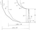
With reference to Fig. 1, the first row airflow diffuser 2 of steamturbine low pressure stage comprises entrance 18, the steam that this entrance 18 receives through the last stage movable vane 14 of turbine.Exhaust stream diffuser 2 also comprises steam guiding surface 4 and diffuser end wall 6, and these steam guiding surface 4 guiding are from the vapor stream of last stage movable vane 14 processes.The axial length L of diffuser (measuring to diffuser end wall 6 according to the center line 16 from last stage movable vane 14) is roughly 2.0 with respect to the ratio of the effective length AL of last stage movable vane 14.The center line 16 of last stage movable vane 14 is the radial line of the center of gravity of the root segment of process movable vane.
Still with reference to Fig. 1, also shown the second diffuser 8 that configuration and diffuser 2 are different.Diffuser 8 has roughly 1.35 axial length L (according to measuring from center line 16 to diffuser end wall 12) with respect to the ratio of the effective length AL of last stage movable vane 14.As shown in Figure 1, the first diffuser 2 has identical diffusion area ratio with the second diffuser 8, and it causes the second diffuser 8 to have the curvature of more precipitous steam guiding surface 10.Because higher curvature, thereby diffusion area ratio may the cause stream identical with the first diffuser of keeping the second diffuser 8 separates from steam guiding surface 10.
Diffuser 8 usefulness leak to strengthen boundary layer along the steam guiding surface 10 of diffuser 8 from the top of crossing of last stage movable vane 14, to reduce or to prevent that steam from separating from steam guiding surface 10.Reduce or prevent that steam from separating from steam guiding surface 10, improved the static pressure recovery.
The top clearance of last stage movable vane 14 can be lowered or minimize, and increases or maximization so that be positioned at the merit of the fluid (for example, steam or hot gas) of the rotation blade of turbine.Can provide the gap of certain tittle to reduce the possibility of the friction between blade and the inner casing.Last stage movable vane 14 can have in the hot radial top gap that for example approximately changes between 125 to 200 mils and for example be approximately 0.5% to 2% the leakage flow rate of circulation rate (annulus flow rate).The top clearance that should realize last stage movable vane 14 can be in addition for example approximately between 50 to 160 mils.
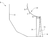
With reference to Fig. 2, the diffuser 8 that has roughly 1.5 L/AL ratio, has roughly 0.45 to 0.70 steam guiding axial length SGL (measuring according to the end from the center line 16 of last stage movable vane 14 to steam guiding surface 10) with respect to the ratio of the effective length AL of last stage movable vane 14, for example, roughly 0.55.With reference to Fig. 3, last stage movable vane 14 for example has approximately 0 ° apex angles A, and the curvature of steam guiding surface 10 can have the first angle B, this first angle B can be corresponding to the excursion of the angle of whole previous 25% warp-wise length (meridional length) of the steam guide portion from slope, movable vane top, be for example 0 ° to 18 °, for example approximately 2 °, 11 ° or 14 °.The the second angle C of curvature that is in the steam guiding surface 10 of 50% warp-wise distance can be for example 14 ° to 32 ° variation, for example approximately 20 °, 22 ° or 28 °.The third angle degree D of curvature that is in the steam guiding surface 10 of 75% warp-wise distance can be for example approximately 16 ° to 32 ° variation, for example approximately 24 °, 26 ° or 28 °.
With reference to Figure 4 and 5, turbine can comprise tilting cover 20.The curvature that last stage movable vane 14 for example has about 25 ° apex angles A and steam guiding surface 10 can have the first angle B, this first angle B can be corresponding to the excursion of the angle of whole previous 25% warp-wise length of the steam guide portion from slope, movable vane top, be for example 0 ° to 18 °, for example approximately 2 °, 11 ° or 14 °.The the second angle C of curvature that is in the steam guiding surface 10 of 50% warp-wise distance can be for example 14 ° to 32 ° variation, for example approximately 20 °, 22 ° or 28 °.The third angle degree D of curvature that is in the steam guiding surface 10 of 75% warp-wise distance can be for example approximately 16 ° to 32 ° variation, for example approximately 24 °, 26 ° or 28 °.
Although described embodiment about steamturbine, should realize diffuser and can use with gas turbine.
Although in conjunction with being considered to the most practical at present and preferred embodiment is described the present invention, but be to be understood that and the invention is not restricted to the disclosed embodiments, on the contrary, be intended to comprise main idea and interior included various modifications and the equivalent arrangements of scope of appended claim.
List of parts
2: the first row airflow diffuser
4: steam guiding surface (first row airflow diffuser)
6: diffuser end wall (first row airflow diffuser)
8: the second row airflow diffuser
10: steam guiding surface (second row airflow diffuser)
12: diffuser end wall (second row airflow diffuser)
14: last stage movable vane
16: the last stage movable vane center line
18: diffusor entry
AL: effective length
L: diffuser length
SGL: steam length of lead

Claims (20)

1. 一种用于涡轮的排气扩散器,包括: 1. An exhaust diffuser for a turbine comprising: 入口,配置成从所述涡轮的末级动叶接收排气;以及 an inlet configured to receive exhaust gas from a last stage bucket of the turbine; and 排气引导表面,配置成引导所述排气,其中,所述引导表面的曲率包括相对于所述涡轮的轴线的第一角度和在约0.45至0.70之间的引导表面的轴向长度相对于所述末级动叶的有效长度的比率。 an exhaust guide surface configured to guide the exhaust gas, wherein the curvature of the guide surface comprises a first angle relative to the axis of the turbine and the axial length of the guide surface is between about 0.45 and 0.70 relative to The ratio of the effective lengths of the final stage buckets. 2. 根据权利要求1所述的排气扩散器,其中,所述引导表面的轴向长度相对于所述有效长度的比率为约0.55。 2. The exhaust diffuser of claim 1, wherein the ratio of the axial length of the guide surface to the effective length is about 0.55. 3. 根据权利要求1所述的排气扩散器,其中,所述排气扩散器的轴向长度相对于所述有效长度的比率在约1.35和2.0之间。 3. The exhaust diffuser of claim 1, wherein the ratio of the axial length to the effective length of the exhaust diffuser is between about 1.35 and 2.0. 4. 根据权利要求1所述的排气扩散器,其中,所述引导表面的曲率包括第二角度和第三角度,且所述第一角度、所述第二角度以及所述第三角度分别对应于处于25%、50%以及75%的经向距离的所述蒸汽引导部的整个先前的25%的经向长度的角度的变化范围。 4. The exhaust diffuser of claim 1 , wherein the curvature of the guide surface includes a second angle and a third angle, and the first angle, the second angle, and the third angle are respectively The range of variation of angles corresponding to the entire previous 25% of the meridional length of the steam guide at 25%, 50% and 75% of the meridional distances. 5. 根据权利要求4所述的排气扩散器,其中,所述第一角度的变化在0°至18°的范围内,所述第二角度的变化在14°至32°的范围内,所述第三角度的变化在16°至32°的范围内。 5. The exhaust diffuser according to claim 4, wherein the variation of the first angle is in the range of 0° to 18°, the variation of the second angle is in the range of 14° to 32°, The variation of the third angle is in the range of 16° to 32°. 6. 根据权利要求4所述的排气扩散器,其中,所述第二角度大于所述第一角度,且所述第三角度大于所述第二角度。 6. The exhaust diffuser of claim 4, wherein the second angle is greater than the first angle, and the third angle is greater than the second angle. 7. 根据权利要求4所述的排气扩散器,其中,所述第二角度和所述第三角度大致相等。 7. The exhaust diffuser of claim 4, wherein the second angle and the third angle are substantially equal. 8. 根据权利要求4所述的排气扩散器,其中,所述第一角度对应于从所述涡轮的所述末级动叶的罩顶部起的25%的经向距离处的角度的变化范围。 8. The exhaust diffuser of claim 4, wherein the first angle corresponds to a change in angle at 25% of the meridional distance from the shroud top of the last stage bucket of the turbine scope. 9. 一种涡轮,包括根据权利要求1所述的扩散器。 9. A turbine comprising a diffuser according to claim 1. 10. 根据权利要求9所述的涡轮,其中,所述末级动叶的顶部和内壳或罩之间的间隙在约50至200密耳之间。 10. The turbine of claim 9, wherein the gap between the tip of the last stage bucket and an inner casing or shroud is between about 50 to 200 mils. 11. 根据权利要求10所述的涡轮,其中,所述间隙在约125至160密耳之间。 11. The turbine of claim 10, wherein the gap is between about 125 to 160 mils. 12. 一种将涡轮的排气扩散的方法,所述方法包括: 12. A method of diffusing exhaust gas from a turbine, the method comprising: 以所述涡轮的末级动叶的过顶部泄漏来加强沿着排气扩散器的弯曲的排气流引导表面的边界层,其中,所述弯曲的排气流引导表面处于相对于所述涡轮的轴线的第一角度,且引导表面的轴向长度相对于所述末级动叶的所述有效长度的比率在约0.45至0.70之间。 Enhancing a boundary layer along a curved exhaust flow directing surface of an exhaust diffuser with over-tip leakage of last stage buckets of the turbine, wherein the curved exhaust flow directing surface is positioned relative to the turbine and the ratio of the axial length of the guide surface relative to the effective length of the last stage bucket is between about 0.45 and 0.70. 13. 根据权利要求12所述的方法,其中,引导表面的轴向长度相对于所述有效长度的比率为约0.55。 13. The method of claim 12, wherein the ratio of the axial length of the guide surface to the effective length is about 0.55. 14. 根据权利要求13所述的方法,其中,所述排气扩散器的轴向长度相对于所述有效长度的比率在约1.35和2.0之间。 14. The method of claim 13, wherein a ratio of an axial length of the exhaust diffuser to the effective length is between about 1.35 and 2.0. 15. 根据权利要求12所述的方法,其中,所述引导表面的曲率包括第二角度和第三角度,且所述第一角度、所述第二角度以及所述第三角度分别对应于处于25%、50%以及75%的经向距离的所述蒸汽引导部的整个先前的25%的经向长度的角度的变化范围。 15. The method of claim 12, wherein the curvature of the guide surface comprises a second angle and a third angle, and the first angle, the second angle and the third angle respectively correspond to Ranges of angular variation over the previous 25% meridional length of the steam guide for 25%, 50% and 75% meridional distances. 16. 根据权利要求15所述的方法,其中,所述第一角度的变化在0°至18°的范围内,所述第二角度的变化在14°至32°的范围内,所述第三角度的变化在16°至32°的范围内。 16. The method according to claim 15 , wherein the variation of the first angle is in the range of 0° to 18°, the variation of the second angle is in the range of 14° to 32°, and the variation of the second angle is in the range of 14° to 32°. The variation of the triangular angle is in the range of 16° to 32°. 17. 根据权利要求15所述的方法,其中,所述第二角度大于所述第一角度,且所述第三角度大于所述第二角度。 17. The method of claim 15, wherein the second angle is greater than the first angle, and the third angle is greater than the second angle. 18. 根据权利要求15所述的方法,其中,所述第二角度和所述第三角度大致相等。 18. The method of claim 15, wherein the second angle and the third angle are approximately equal. 19. 根据权利要求15所述的方法,其中,所述第一角度对应于从所述涡轮的所述末级动叶的罩顶部起的25%的经向距离处的角度的变化范围。 19. The method of claim 15, wherein the first angle corresponds to a range of angles at 25% of the meridional distance from a shroud tip of the last stage bucket of the turbine. 20. 根据权利要求12所述的方法,其中,所述末级动叶的顶部和内壳或罩之间的间隙在约50至200密耳之间。 20. The method of claim 12, wherein the clearance between the tip of the last stage bucket and an inner casing or shroud is between about 50 to 200 mils.
CN2013100811952A 2012-03-14 2013-03-14 Exhaust diffuser for a turbine Pending CN103306754A (en)

Applications Claiming Priority (2)

Application Number Priority Date Filing Date Title
US13/419860 2012-03-14
US13/419,860 US20130243564A1 (en) 2012-03-14 2012-03-14 Exhaust diffuser for turbine

Publications (1)

Publication Number Publication Date
CN103306754A true CN103306754A (en) 2013-09-18

Family

ID=47845843

Family Applications (1)

Application Number Title Priority Date Filing Date
CN2013100811952A Pending CN103306754A (en) 2012-03-14 2013-03-14 Exhaust diffuser for a turbine

Country Status (5)

Country Link
US (1) US20130243564A1 (en)
EP (1) EP2639404A1 (en)
JP (1) JP2013189975A (en)
CN (1) CN103306754A (en)
RU (1) RU2013111162A (en)

Cited By (1)

* Cited by examiner, † Cited by third party
Publication number Priority date Publication date Assignee Title
CN107923247A (en) * 2015-08-12 2018-04-17 通用电气公司 Diffuser and its forming method for turbogenerator

Families Citing this family (4)

* Cited by examiner, † Cited by third party
Publication number Priority date Publication date Assignee Title
US9598981B2 (en) * 2013-11-22 2017-03-21 Siemens Energy, Inc. Industrial gas turbine exhaust system diffuser inlet lip
CN104074554B (en) * 2014-06-13 2016-01-13 东方电气集团东方汽轮机有限公司 Indirect air cooling final stage moving blade
EP3054086B1 (en) * 2015-02-05 2017-09-13 General Electric Technology GmbH Steam turbine diffuser configuration
EP3653850B1 (en) 2018-11-16 2021-09-29 Doosan Skoda Power S.r.o. Exhaust diffuser for a steam turbine and corresponding steam turbine

Citations (7)

* Cited by examiner, † Cited by third party
Publication number Priority date Publication date Assignee Title
US4013378A (en) * 1976-03-26 1977-03-22 General Electric Company Axial flow turbine exhaust hood
US5257906A (en) * 1992-06-30 1993-11-02 Westinghouse Electric Corp. Exhaust system for a turbomachine
US6261055B1 (en) * 1999-08-03 2001-07-17 Jerzy A. Owczarek Exhaust flow diffuser for a steam turbine
US20020018714A1 (en) * 1999-02-15 2002-02-14 Peter Kraus Diffusor without any pulsation of the shock boundary layer, and a method for suppressing the shock boundary layer pulsation in diffusors
US20080063516A1 (en) * 2006-09-08 2008-03-13 Siemens Power Generation, Inc. Adjustable turbine exhaust flow guide and bearing cone assemblies
CN101839148A (en) * 2009-03-16 2010-09-22 株式会社日立制作所 Steam turbine rotor blade and corresponding steam turbine
EP2378077A2 (en) * 2010-04-13 2011-10-19 General Electric Company Shroud vortex remover

Family Cites Families (7)

* Cited by examiner, † Cited by third party
Publication number Priority date Publication date Assignee Title
CH484358A (en) * 1968-02-15 1970-01-15 Escher Wyss Ag Exhaust housing of an axial turbo machine
FR2401311A1 (en) * 1977-08-25 1979-03-23 Europ Turb Vapeur EXHAUST SYSTEM FOR AXIAL CONDENSABLE FLUID TURBINE
US5494405A (en) * 1995-03-20 1996-02-27 Westinghouse Electric Corporation Method of modifying a steam turbine
DE10037684A1 (en) * 2000-07-31 2002-02-14 Alstom Power Nv Low pressure steam turbine with multi-channel diffuser
US8439633B2 (en) * 2010-01-04 2013-05-14 General Electric Company Hollow steam guide diffuser having increased pressure recovery
US9249687B2 (en) * 2010-10-27 2016-02-02 General Electric Company Turbine exhaust diffusion system and method
JP5606473B2 (en) * 2012-02-24 2014-10-15 株式会社東芝 Steam turbine

Patent Citations (7)

* Cited by examiner, † Cited by third party
Publication number Priority date Publication date Assignee Title
US4013378A (en) * 1976-03-26 1977-03-22 General Electric Company Axial flow turbine exhaust hood
US5257906A (en) * 1992-06-30 1993-11-02 Westinghouse Electric Corp. Exhaust system for a turbomachine
US20020018714A1 (en) * 1999-02-15 2002-02-14 Peter Kraus Diffusor without any pulsation of the shock boundary layer, and a method for suppressing the shock boundary layer pulsation in diffusors
US6261055B1 (en) * 1999-08-03 2001-07-17 Jerzy A. Owczarek Exhaust flow diffuser for a steam turbine
US20080063516A1 (en) * 2006-09-08 2008-03-13 Siemens Power Generation, Inc. Adjustable turbine exhaust flow guide and bearing cone assemblies
CN101839148A (en) * 2009-03-16 2010-09-22 株式会社日立制作所 Steam turbine rotor blade and corresponding steam turbine
EP2378077A2 (en) * 2010-04-13 2011-10-19 General Electric Company Shroud vortex remover

Cited By (2)

* Cited by examiner, † Cited by third party
Publication number Priority date Publication date Assignee Title
CN107923247A (en) * 2015-08-12 2018-04-17 通用电气公司 Diffuser and its forming method for turbogenerator
CN107923247B (en) * 2015-08-12 2020-12-25 通用电气公司 Diffuser for a turbine engine and method of forming the same

Also Published As

Publication number Publication date
EP2639404A1 (en) 2013-09-18
JP2013189975A (en) 2013-09-26
RU2013111162A (en) 2014-09-20
US20130243564A1 (en) 2013-09-19

Similar Documents

Publication Publication Date Title
CN103527260B (en) Aerofoil profile
CN103711531B (en) The exhaust gas diffuser of combustion gas turbine
CN103089319B (en) The turbine of turbine and turbine
CN105026697B (en) Radial diffuser gas extraction system
CN103306754A (en) Exhaust diffuser for a turbine
CN102252345A (en) Tangential combustor
JP2012132455A (en) Turbine including exhaust hood
CN103089316A (en) Turbine last stage flow path
JP6018368B2 (en) Tip channel contour
CN107448293A (en) Exhaust diffuser for gas-turbine unit
CN102373960B (en) turbine device
CN103244209A (en) Diffuser end wall of turbine single-side exhaust system
JP4848440B2 (en) Axial flow turbine
US20120121405A1 (en) Low pressure exhaust gas diffuser for a steam turbine
CN105888750A (en) Steam turbine diffuser configuration
US10844731B2 (en) Cantilevered vane and gas turbine including the same
JP2017008756A (en) Axial flow turbine
CN103206273A (en) Diffuser for gas turbine
JP2017089637A (en) System for integrating turbine parts
CN103670526A (en) Method of clocking a turbine by reshaping the turbine's downstream airfoils
CN103511008B (en) Diffuser for turbomachines
CN110199092A (en) Exhaust system for gas-turbine unit
CN105531544A (en) Combustion chamber for a gas turbine, and tool and method for producing cooling ducts in a gas turbine component
JP2014202210A (en) Gas turbine exhaust diffuser
US20180258778A1 (en) Non-axially symmetric transition ducts for combustors

Legal Events

Date Code Title Description
C06 Publication
PB01 Publication
C10 Entry into substantive examination
SE01 Entry into force of request for substantive examination
C02 Deemed withdrawal of patent application after publication (patent law 2001)
WD01 Invention patent application deemed withdrawn after publication

Application publication date: 20130918