CN103402829A - Gas generator - Google Patents

Gas generator Download PDF

Info

Publication number
CN103402829A
CN103402829A CN2012800047399A CN201280004739A CN103402829A CN 103402829 A CN103402829 A CN 103402829A CN 2012800047399 A CN2012800047399 A CN 2012800047399A CN 201280004739 A CN201280004739 A CN 201280004739A CN 103402829 A CN103402829 A CN 103402829A
Authority
CN
China
Prior art keywords
mentioned
gas generator
filter
base plate
gas
Prior art date
Legal status (The legal status is an assumption and is not a legal conclusion. Google has not performed a legal analysis and makes no representation as to the accuracy of the status listed.)
Pending
Application number
CN2012800047399A
Other languages
Chinese (zh)
Inventor
大杉知士
椋木大刚
田中雄佑
Current Assignee (The listed assignees may be inaccurate. Google has not performed a legal analysis and makes no representation or warranty as to the accuracy of the list.)
Nippon Kayaku Co Ltd
Original Assignee
Nippon Kayaku Co Ltd
Priority date (The priority date is an assumption and is not a legal conclusion. Google has not performed a legal analysis and makes no representation as to the accuracy of the date listed.)
Filing date
Publication date
Application filed by Nippon Kayaku Co Ltd filed Critical Nippon Kayaku Co Ltd
Publication of CN103402829A publication Critical patent/CN103402829A/en
Pending legal-status Critical Current

Links

Images

Classifications

    • CCHEMISTRY; METALLURGY
    • C06EXPLOSIVES; MATCHES
    • C06DMEANS FOR GENERATING SMOKE OR MIST; GAS-ATTACK COMPOSITIONS; GENERATION OF GAS FOR BLASTING OR PROPULSION (CHEMICAL PART)
    • C06D5/00Generation of pressure gas, e.g. for blasting cartridges, starting cartridges, rockets
    • BPERFORMING OPERATIONS; TRANSPORTING
    • B60VEHICLES IN GENERAL
    • B60RVEHICLES, VEHICLE FITTINGS, OR VEHICLE PARTS, NOT OTHERWISE PROVIDED FOR
    • B60R21/00Arrangements or fittings on vehicles for protecting or preventing injuries to occupants or pedestrians in case of accidents or other traffic risks
    • B60R21/02Occupant safety arrangements or fittings, e.g. crash pads
    • B60R21/16Inflatable occupant restraints or confinements designed to inflate upon impact or impending impact, e.g. air bags
    • B60R21/26Inflatable occupant restraints or confinements designed to inflate upon impact or impending impact, e.g. air bags characterised by the inflation fluid source or means to control inflation fluid flow
    • B60R21/264Inflatable occupant restraints or confinements designed to inflate upon impact or impending impact, e.g. air bags characterised by the inflation fluid source or means to control inflation fluid flow using instantaneous generation of gas, e.g. pyrotechnic
    • B60R21/2644Inflatable occupant restraints or confinements designed to inflate upon impact or impending impact, e.g. air bags characterised by the inflation fluid source or means to control inflation fluid flow using instantaneous generation of gas, e.g. pyrotechnic using only solid reacting substances, e.g. pellets, powder
    • BPERFORMING OPERATIONS; TRANSPORTING
    • B60VEHICLES IN GENERAL
    • B60RVEHICLES, VEHICLE FITTINGS, OR VEHICLE PARTS, NOT OTHERWISE PROVIDED FOR
    • B60R21/00Arrangements or fittings on vehicles for protecting or preventing injuries to occupants or pedestrians in case of accidents or other traffic risks
    • B60R21/02Occupant safety arrangements or fittings, e.g. crash pads
    • B60R21/16Inflatable occupant restraints or confinements designed to inflate upon impact or impending impact, e.g. air bags
    • B60R21/26Inflatable occupant restraints or confinements designed to inflate upon impact or impending impact, e.g. air bags characterised by the inflation fluid source or means to control inflation fluid flow
    • B60R2021/26011Inflatable occupant restraints or confinements designed to inflate upon impact or impending impact, e.g. air bags characterised by the inflation fluid source or means to control inflation fluid flow using a filter through which the inflation gas passes
    • BPERFORMING OPERATIONS; TRANSPORTING
    • B60VEHICLES IN GENERAL
    • B60RVEHICLES, VEHICLE FITTINGS, OR VEHICLE PARTS, NOT OTHERWISE PROVIDED FOR
    • B60R21/00Arrangements or fittings on vehicles for protecting or preventing injuries to occupants or pedestrians in case of accidents or other traffic risks
    • B60R21/02Occupant safety arrangements or fittings, e.g. crash pads
    • B60R21/16Inflatable occupant restraints or confinements designed to inflate upon impact or impending impact, e.g. air bags
    • B60R21/26Inflatable occupant restraints or confinements designed to inflate upon impact or impending impact, e.g. air bags characterised by the inflation fluid source or means to control inflation fluid flow
    • B60R2021/26076Inflatable occupant restraints or confinements designed to inflate upon impact or impending impact, e.g. air bags characterised by the inflation fluid source or means to control inflation fluid flow characterised by casing
    • B60R2021/26082Material
    • B60R2021/26088Plastic
    • BPERFORMING OPERATIONS; TRANSPORTING
    • B60VEHICLES IN GENERAL
    • B60RVEHICLES, VEHICLE FITTINGS, OR VEHICLE PARTS, NOT OTHERWISE PROVIDED FOR
    • B60R21/00Arrangements or fittings on vehicles for protecting or preventing injuries to occupants or pedestrians in case of accidents or other traffic risks
    • B60R21/02Occupant safety arrangements or fittings, e.g. crash pads
    • B60R21/16Inflatable occupant restraints or confinements designed to inflate upon impact or impending impact, e.g. air bags
    • B60R21/26Inflatable occupant restraints or confinements designed to inflate upon impact or impending impact, e.g. air bags characterised by the inflation fluid source or means to control inflation fluid flow
    • B60R21/264Inflatable occupant restraints or confinements designed to inflate upon impact or impending impact, e.g. air bags characterised by the inflation fluid source or means to control inflation fluid flow using instantaneous generation of gas, e.g. pyrotechnic
    • B60R21/2644Inflatable occupant restraints or confinements designed to inflate upon impact or impending impact, e.g. air bags characterised by the inflation fluid source or means to control inflation fluid flow using instantaneous generation of gas, e.g. pyrotechnic using only solid reacting substances, e.g. pellets, powder
    • B60R2021/2648Inflatable occupant restraints or confinements designed to inflate upon impact or impending impact, e.g. air bags characterised by the inflation fluid source or means to control inflation fluid flow using instantaneous generation of gas, e.g. pyrotechnic using only solid reacting substances, e.g. pellets, powder comprising a plurality of combustion chambers or sub-chambers

Landscapes

  • Chemical & Material Sciences (AREA)
  • Engineering & Computer Science (AREA)
  • Physics & Mathematics (AREA)
  • Fluid Mechanics (AREA)
  • Mechanical Engineering (AREA)
  • Chemical Kinetics & Catalysis (AREA)
  • Combustion & Propulsion (AREA)
  • Organic Chemistry (AREA)
  • Air Bags (AREA)
  • Feeding, Discharge, Calcimining, Fusing, And Gas-Generation Devices (AREA)

Abstract

A gas generator (1A) is provided with a housing that includes a lower-side shell (10) and an upper-side shell (20), an igniter (40), a gas-generating agent (61), and filters (70). The housing includes a bottom plate section (11) to which the igniter (40) is attached, and contains a combustion chamber (60), inside which the gas-generating agent (61) is contained. The filters (70) comprise hollow cylindrical members, and are disposed inside the housing in such a manner as to enclose the ignition chamber (60) in the radial direction of the housing. A fluid resin material is formed on the bottom plate section (11) by attaching the fluid resin material to the inner surface and setting the fluid resin material, thereby providing positioning parts (38) comprising resin moldings fixed to the bottom plate section (11). The positioning parts (38) are in contact with the inner peripheral surface of the axial ends positioned on the bottom plate section (11) side of the filters (70).

Description

气体发生器The gas generator

技术领域 technical field

本发明涉及装入在乘员保护装置中的气体发生器,更特定地讲,涉及装入到气囊装置中的所谓盘型气体发生器,所述气囊装置装备在汽车的方向盘等上。 The present invention relates to a gas generator incorporated in an occupant protection device, and more particularly, to a so-called disc-type gas generator incorporated in an airbag device equipped on a steering wheel or the like of an automobile.

背景技术 Background technique

以往,从汽车等的乘员的保护的观点,作为乘员保护装置的气囊装置已普及。气囊装置是以从在车辆等碰撞时发生的冲击保护乘员的目的装备的,通过在车辆等碰撞时瞬间使气囊膨胀及展开,气囊成为缓冲垫而承接住乘员的身体。气体发生器是下述设备:装入在该气囊装置中,在车辆等碰撞时通过从控制单元的通电而将点火器点火,通过在点火器中产生的火焰使气体发生剂燃烧而瞬间产生大量的气体,由此使气囊膨胀及展开。另外,气囊装置例如装备在汽车的方向盘或仪表板等上。 Conventionally, airbag devices have been widely used as occupant protection devices from the viewpoint of occupant protection of automobiles and the like. The airbag device is equipped for the purpose of protecting the occupant from the impact that occurs when a vehicle or the like collides. When the vehicle or the like collides, the airbag is instantly inflated and deployed, and the airbag acts as a cushion to support the occupant's body. The gas generator is a device that is incorporated in the airbag device, and when a vehicle or the like collides, the igniter is ignited by energization from the control unit, and the gas generating agent is burned by the flame generated in the igniter to generate a large amount of gas in an instant. gas, thereby inflating and deploying the airbag. In addition, the airbag device is equipped, for example, on a steering wheel, an instrument panel, or the like of an automobile.

在气体发生器中存在各种构造的气体发生器,但作为特别适合在驾驶席侧气囊装置中使用的气体发生器,有所谓的盘型气体发生器,所述驾驶席侧气囊装置装备于方向盘等上。一般而言,盘型气体发生器具有轴向的端部被闭塞的短尺寸圆筒状的壳体,在壳体的周壁上设有气体喷出口并在壳体的内部收容有气体发生剂及点火器、过滤器等。 There are gas generators of various structures among gas generators, but as a gas generator that is particularly suitable for use in a driver's side airbag device, there is a so-called disc-type gas generator that is equipped on a steering wheel. wait. In general, a disc-shaped gas generator has a short cylindrical casing with its axial ends closed, a gas outlet is provided on the peripheral wall of the casing, and a gas generating agent and Igniters, filters, etc.

在该盘型气体发生器中,一般过滤器以将收容有气体发生剂的燃烧室包围的方式收容配置在壳体的内部。过滤器作为将在由燃烧室产生的气体中含有的熔渣(残渣)捕集而除去的除去机构发挥功能,并且还作为通过该气体穿过内部而使其温度下降的冷却机构发挥功能。 In this disc-shaped gas generator, generally, the filter is housed and arranged inside the casing so as to surround the combustion chamber in which the gas generating agent is housed. The filter functions as a removal mechanism for trapping and removing slag (residue) contained in the gas generated in the combustion chamber, and also functions as a cooling mechanism for lowering the temperature of the gas as it passes through the inside.

通常,壳体由构成周壁部的一部分及底板部的有底大致圆筒状的下部侧壳、和构成周壁部的剩余一部分及顶板部的有底大致圆筒状的上部侧壳构成的情况较多,在此情况下,上述过滤器通过被这些下部侧壳和上部侧壳夹入而组装在壳体上。 Usually, the casing is composed of a bottomed substantially cylindrical lower side shell constituting a part of the peripheral wall portion and the bottom plate portion, and a bottomed substantially cylindrical upper side shell constituting the remaining portion of the peripheral wall portion and the top plate portion. Many, in this case, the above-mentioned filter is assembled on the housing by being sandwiched by these lower side shells and upper side shells.

此时,在壳体的内部的过滤器的定位中,使用设置在下部侧壳的底板部上的环状的金属制板状部件。该金属制板状部件在其外周缘上具有在组装后抵接在过滤器的内周面上的抵接部,在过滤器的组装时,通过将过滤器外插到该金属制板状部件的抵接部上而进行过滤器的径向上的定位。 At this time, an annular metal plate member provided on the bottom plate portion of the lower case is used for positioning the filter inside the housing. The metal plate-shaped member has a contact portion on its outer peripheral edge that abuts against the inner peripheral surface of the filter after assembly, and when the filter is assembled, the filter is inserted into the metal plate-shaped member The radial positioning of the filter is carried out on the abutting part of the filter.

这里,上述金属制板状部件还具有作为流出防止部件的功能,在组装后沿着规定燃烧室的过滤器的内周面和下部侧壳的内表面配置,所述流出防止部件在气体发生器的动作时,防止气体从过滤器与下部侧壳之间的间隙一部分流出且不经过过滤器的内部被从气体喷出口喷出。 Here, the above-mentioned metal plate-shaped member also functions as an outflow prevention member, and is arranged along the inner peripheral surface of the filter defining the combustion chamber and the inner surface of the lower side casing after assembly. During the operation, the gas is prevented from flowing out from a part of the gap between the filter and the lower side shell and being ejected from the gas outlet without passing through the inside of the filter.

另外,作为采用了上述结构的气体发生器,例如有在特开平10-81190号公报(专利文献1)或特开平11-189126号公报(专利文献2)、特开2007-290620号公报(专利文献3)等中公开的结构。 In addition, as a gas generator adopting the above-mentioned structure, there are, for example, Japanese Unexamined Patent Publication No. 10-81190 (Patent Document 1), Japanese Unexamined Publication No. 11-189126 (Patent Document 2), and Japanese Unexamined Publication No. 2007-290620 (Patent Document 2). The structure disclosed in Document 3) et al.

专利文献1:特开平10-81190号公报 Patent Document 1: Japanese Unexamined Patent Publication No. 10-81190

专利文献2:特开平11-189126号公报 Patent Document 2: Japanese Unexamined Patent Publication No. 11-189126

专利文献3:特开2007-290620号公报。 Patent Document 3: JP-A-2007-290620.

发明内容 Contents of the invention

但是,在采用了上述公报的任一个中公开那样的结构的情况下,有在气体发生剂的填充工序中,发生不良状况的情况。通常,在气体发生剂的填充工序中,在下部侧壳上组装了上述金属制板状部件及过滤器的状态下将规定量的气体发生剂填充到燃烧室中,但此时为了将由成形体构成的气体发生剂紧密地填充到燃烧室中,一般进行对下部侧壳施加振动的操作。 However, when the structure disclosed in any of the above-mentioned publications is adopted, problems may occur in the filling process of the gas generating agent. Usually, in the gas generating agent filling process, a predetermined amount of gas generating agent is filled into the combustion chamber in the state where the above-mentioned metal plate-shaped member and filter are assembled on the lower side shell, but at this time, in order to The constituted gas generating agent is densely filled into the combustion chamber, and the operation of applying vibration to the lower side casing is generally performed.

此时,上述金属制板状部件因振动而晃动,根据情况,有发生通过金属制板状部件浮起而气体发生剂进入到金属制板状部件与下部侧壳之间的不良状况的情况。在发生了该不良状况的情况下,不能进行规定量的气体发生剂的填充,而需要将气体发生剂取出、再次实施填充工序等的作业,有制造工序变复杂的问题。 At this time, the metal plate-like member shakes due to vibration, and depending on the case, the gas generating agent may enter between the metal plate-like member and the lower side shell due to the floating of the metal plate-like member. When this problem occurs, a predetermined amount of the gas generating agent cannot be filled, and it is necessary to take out the gas generating agent and perform operations such as a filling process again, and there is a problem that the manufacturing process becomes complicated.

此外,在采用了上述公报的任一个中公开那样的结构的情况下,需要将上述金属制板状部件配置到下部侧壳上,还有导致伴随着零件件数的增加的组装作业的复杂化的问题、以及通过该金属制板状部件的追加而发生作为气体发生器整体的重量的增加的问题。 In addition, in the case of adopting the structure disclosed in any of the above publications, it is necessary to arrange the above-mentioned metal plate-shaped member on the lower side shell, and there is also the possibility of complicating the assembly work accompanying the increase in the number of parts. Problem, and the problem that the weight of the gas generator as a whole increases due to the addition of the metal plate member.

因而,本发明是为了解决上述问题而做出的,目的是提供一种能够没有不良状况而容易地制造、并且能实现轻量化的气体发生器。 Therefore, the present invention was made to solve the above-mentioned problems, and an object of the present invention is to provide a gas generator that can be easily manufactured without problems and can achieve weight reduction.

基于本发明的第1技术方案的气体发生器具备壳体、点火器、过滤器和定位部。上述壳体由将轴向的端部闭塞的顶板部及底板部、和设有气体喷出口的周壁部构成,由在内部包括收容有气体发生剂的燃烧室的短尺寸筒状的部件构成。上述点火器用来使上述气体发生剂燃烧,组装在上述底板部上。上述过滤器配设在上述壳体的内部,由将上述燃烧室在上述壳体的径向上包围的中空筒状的部件构成。上述壳体至少具有包括上述底板部的下部侧壳、和包括上述顶板部的上部侧壳。上述定位部由树脂成形部构成,通过抵接在上述过滤器的位于上述底板部侧的轴向端部的内周面及外周面中的至少一方上而进行上述过滤器的径向上的定位,所述树脂成形部通过使流动性树脂材料附着在上述下部侧壳的内表面上并使其固化而形成,由此至少其一部分固接在上述下部侧壳上。 A gas generator according to a first aspect of the present invention includes a case, an igniter, a filter, and a positioning unit. The housing is composed of a top plate and a bottom plate that close the ends in the axial direction, and a peripheral wall portion provided with gas injection ports, and is composed of a short cylindrical member including a combustion chamber containing a gas generating agent therein. The igniter is used to ignite the gas generating agent, and is assembled on the bottom plate. The said filter is arrange|positioned inside the said casing, and is comprised by the hollow cylindrical member which surrounds the said combustion chamber in the radial direction of the said casing. The casing includes at least a lower side case including the bottom plate portion, and an upper side case including the top plate portion. The positioning portion is formed of a resin molded portion, and is positioned in the radial direction of the filter by abutting against at least one of an inner peripheral surface and an outer peripheral surface of an axial end portion of the filter on the bottom plate side, The resin molded portion is formed by adhering a fluid resin material to the inner surface of the lower shell and curing it, whereby at least a part thereof is fixed to the lower shell.

基于本发明的第2技术方案的气体发生器具备壳体、点火器、过滤器和保持部。上述壳体由将轴向的端部闭塞的顶板部及底板部、和设有气体喷出口的周壁部构成,由在内部包括收容有气体发生剂的燃烧室的短尺寸筒状的部件构成。上述点火器用来使上述气体发生剂燃烧,组装在上述底板部上。上述过滤器配设在上述壳体的内部,由将上述燃烧室在上述壳体的径向上包围的中空筒状的部件构成。上述保持部设在上述底板部上,保持上述点火器。上述壳体至少具有包括上述底板部的下部侧壳、和包括上述顶板部的上部侧壳。上述下部侧壳包括朝向上述顶板部侧突出设置的突状筒部、和设在上述突状筒部的位于上述顶板部侧的轴向端部上的开口部。上述保持部由树脂成形部构成,所述树脂成形部通过使流动性树脂材料以经由上述开口部至少从上述底板部的内表面的一部分达到上述底板部的外表面的一部分的方式附着在上述底板部上并使其固化而形成,由此至少其一部分固接在上述底板部上,上述保持部包括:保持部主体,保持上述点火器;延伸设置部,从上述保持部主体沿着上述底板部的内表面朝向外侧延伸;和定位部,设在上述延伸设置部上,通过抵接在上述过滤器的位于上述底板部侧的轴向端部的内周面及外周面中的至少一方上,进行上述过滤器的径向上的定位。 A gas generator according to a second aspect of the present invention includes a case, an igniter, a filter, and a holding unit. The housing is composed of a top plate and a bottom plate that close the ends in the axial direction, and a peripheral wall portion provided with gas injection ports, and is composed of a short cylindrical member including a combustion chamber containing a gas generating agent therein. The igniter is used to ignite the gas generating agent, and is assembled on the bottom plate. The said filter is arrange|positioned inside the said casing, and is comprised by the hollow cylindrical member which surrounds the said combustion chamber in the radial direction of the said casing. The holding part is provided on the bottom plate part, and holds the igniter. The casing includes at least a lower side case including the bottom plate portion, and an upper side case including the top plate portion. The lower shell includes a protruding cylindrical portion protruding toward the top plate side, and an opening provided at an axial end portion of the protruding cylindrical portion on the top plate side. The holding portion is formed of a resin molded portion that adheres a fluid resin material to the bottom plate so as to extend from at least a part of the inner surface of the bottom plate portion to a part of the outer surface of the bottom plate portion through the opening. part and solidified, so that at least a part of it is fixed on the above-mentioned bottom plate part, the above-mentioned holding part includes: a holding part main body, holding the above-mentioned igniter; an extending part, from the above-mentioned holding part main body The inner surface of the filter extends toward the outside; and the positioning part is provided on the above-mentioned extending part, and by abutting on at least one of the inner peripheral surface and the outer peripheral surface of the axial end portion of the filter on the side of the bottom plate part, The positioning of the filter in the radial direction is carried out.

在上述基于本发明的第2技术方案的气体发生器中,优选的是,上述延伸设置部固接在上述底板部上。 In the gas generator according to the second aspect of the present invention, preferably, the extended portion is fixedly attached to the bottom plate portion.

在上述基于本发明的第1及第2技术方案的气体发生器中,优选的是,上述定位部具有沿着上述过滤器的周向抵接在上述过滤器上的环状的形状。 In the above gas generators according to the first and second aspects of the present invention, it is preferable that the positioning portion has an annular shape that abuts on the filter along the circumferential direction of the filter.

在上述基于本发明的第1及第2技术方案的气体发生器中,可以是,上述定位部沿着上述过滤器的周向排列配置有多个。 In the above-mentioned gas generators based on the first and second aspects of the present invention, a plurality of the positioning parts may be arranged along the circumferential direction of the filter.

在上述基于本发明的第1及第2技术方案的气体发生器中,优选的是,上述定位部位于面对上述燃烧室的部分的上述底板部上,仅抵接在上述过滤器的位于上述底板部侧的轴向端部的内周面上。 In the above-mentioned gas generators based on the first and second technical solutions of the present invention, it is preferable that the positioning part is located on the bottom plate part of the part facing the combustion chamber, and only abuts against the part of the filter located on the On the inner peripheral surface of the axial end portion on the bottom plate side.

在上述基于本发明的第1及第2技术方案的气体发生器中,优选的是,上述下部侧壳由通过将一片金属制的板状部件进行压力加工而成形的压力成形品构成。 In the above-mentioned gas generators according to the first and second aspects of the present invention, it is preferable that the lower side shell is formed of a press-formed product formed by press-working a single metal plate-shaped member.

根据本发明,能够做成能够没有不良状况而容易地制造、并且能实现轻量化的气体发生器。 According to the present invention, it is possible to provide a gas generator that can be easily manufactured without any inconvenience and can be reduced in weight.

附图说明 Description of drawings

图1是本发明的实施方式1的气体发生器的概略图。 FIG. 1 is a schematic diagram of a gas generator according to Embodiment 1 of the present invention.

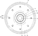
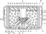
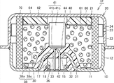
图2是本发明的实施方式1的气体发生器的下部侧壳的俯视图。 Fig. 2 is a plan view of a lower case of the gas generator according to Embodiment 1 of the present invention.

图3表示在本发明的实施方式1的气体发生器的下部侧壳上组装过滤器的状况的概略图。 Fig. 3 is a schematic diagram showing a state in which a filter is assembled to a lower side casing of the gas generator according to Embodiment 1 of the present invention.

图4是基于本发明的实施方式1的变形例的气体发生器的下部侧壳的俯视图。 4 is a plan view of a lower case of a gas generator according to a modified example of Embodiment 1 of the present invention.

图5是本发明的实施方式2的气体发生器的概略图。 Fig. 5 is a schematic diagram of a gas generator according to Embodiment 2 of the present invention.

图6是本发明的实施方式3的气体发生器的概略图。 Fig. 6 is a schematic diagram of a gas generator according to Embodiment 3 of the present invention.

图7是本发明的实施方式4的气体发生器的概略图。 Fig. 7 is a schematic diagram of a gas generator according to Embodiment 4 of the present invention.

图8是本发明的实施方式4的气体发生器的下部侧壳的俯视图。 8 is a plan view of a lower case of a gas generator according to Embodiment 4 of the present invention.

图9是基于本发明的实施方式4的第1变形例的气体发生器的下部侧壳的俯视图。 9 is a plan view of a lower case of a gas generator according to a first modified example of Embodiment 4 of the present invention.

图10是基于本发明的实施方式4的第2变形例的气体发生器的下部侧壳的俯视图。 10 is a plan view of a lower case of a gas generator according to a second modified example of Embodiment 4 of the present invention.

图11是本发明的实施方式5的气体发生器的概略图。 Fig. 11 is a schematic diagram of a gas generator according to Embodiment 5 of the present invention.

图12是本发明的实施方式5的气体发生器的下部侧壳的俯视图。 Fig. 12 is a plan view of a lower case of a gas generator according to Embodiment 5 of the present invention.

图13是本发明的实施方式6的气体发生器的概略图。 Fig. 13 is a schematic diagram of a gas generator according to Embodiment 6 of the present invention.

具体实施方式 Detailed ways

以下,参照附图对本发明的实施方式详细地说明。以下所示的实施方式及其变形例是在装入在气囊装置中的盘型气体发生器中应用了本发明的形态,所述气囊装置装备于汽车的方向盘等上。另外,在以下所示的实施方式及其变形例中,对于相同或共同的部分在图中赋予相同的附图标记而不重复其说明。 Hereinafter, embodiments of the present invention will be described in detail with reference to the drawings. Embodiments and modifications thereof shown below are forms in which the present invention is applied to a disc-shaped gas generator incorporated in an airbag device mounted on a steering wheel or the like of an automobile. In addition, in embodiment and its modification shown below, the same code|symbol is attached|subjected to the same or common part in drawing, and the description is not repeated.

(实施方式1) (implementation mode 1)

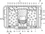
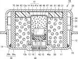
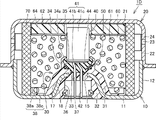
图1是本发明的实施方式1的气体发生器的概略图。此外,图2是图1所示的气体发生器的下部侧壳的俯视图。首先,参照这些图1及图2对本实施方式的气体发生器1A的构造进行说明。 FIG. 1 is a schematic diagram of a gas generator according to Embodiment 1 of the present invention. In addition, FIG. 2 is a plan view of a lower side case of the gas generator shown in FIG. 1 . First, the structure of a gas generator 1A according to the present embodiment will be described with reference to these FIGS. 1 and 2 .

如图1所示,本实施方式的气体发生器1A具有轴向的两端被闭塞的短尺寸圆筒状的壳体,在该壳体的内部收容作为构成零件的点火器40、气体发生剂61、过滤器70等而构成。 As shown in FIG. 1 , a gas generator 1A according to this embodiment has a short cylindrical casing with both ends in the axial direction closed, and accommodates an igniter 40 and a gas generating agent as components inside the casing. 61, filter 70 and so on.

短尺寸圆筒状的壳体包括下部侧壳10和上部侧壳20。下部侧壳10及上部侧壳20分别形成为有底大致圆筒状,通过将这些开口面彼此相向组合并接合,构成壳体的外壳部分。下部侧壳10具有底板部11和周壁部12,上部侧壳20具有顶板部21和周壁部22。 The short cylindrical casing includes a lower side shell 10 and an upper side shell 20 . The lower side shell 10 and the upper side shell 20 are respectively formed in a substantially cylindrical shape with a bottom, and these opening surfaces are combined and joined to face each other to constitute an outer shell portion of the housing. The lower side case 10 has a bottom plate portion 11 and a peripheral wall portion 12 , and the upper side case 20 has a top plate portion 21 and a peripheral wall portion 22 .

下部侧壳10及上部侧壳20都由不锈钢或钢铁、铝合金、不锈钢合金等金属制的部件构成。下部侧壳10从一片块状的金属部件使用金属模等通过锻造加工、拉深加工、压力加工等或它们的组合而形成。上部侧壳20由通过将一片金属制的板状部件压力加工而形成的压力成形品构成。另外,在下部侧壳10与上部侧壳20的接合中,优选的是使用电子束焊接或激光焊接、摩擦压接等。 Both the lower side shell 10 and the upper side shell 20 are made of metal members such as stainless steel, steel, aluminum alloy, and stainless steel alloy. The lower side shell 10 is formed from a block-shaped metal member by forging, drawing, pressing, or the like, or a combination thereof, using a die or the like. The upper side shell 20 is composed of a press-formed product formed by press-working a single metal plate-shaped member. In addition, in joining the lower side shell 10 and the upper side shell 20 , it is preferable to use electron beam welding, laser welding, frictional pressure welding, or the like.

在下部侧壳10的底板部11的大致中央部,形成有安装部13。该安装部13是安装点火器40的部位。具体而言,以在设于安装部13上的开口部15中插通点火器40的端子销42的方式,将点火器40从下部侧壳10的内侧安装到设在安装部13上的收容凹部14中,在此状态下,通过将设在安装部13的前端上的敛缝部13a朝向点火器40侧敛缝,将点火器40敛缝固定在下部侧壳10的安装部13上。 A mounting portion 13 is formed substantially at the center of the bottom plate portion 11 of the lower side case 10 . The mounting portion 13 is a portion where the igniter 40 is mounted. Specifically, the igniter 40 is mounted from the inside of the lower side case 10 to the housing provided on the mounting portion 13 in such a manner that the terminal pin 42 of the igniter 40 is inserted through the opening 15 provided on the mounting portion 13 . In the concave portion 14, in this state, the igniter 40 is fixed to the mounting portion 13 of the lower case 10 by caulking the caulking portion 13a provided on the front end of the mounting portion 13 toward the igniter 40 side.

另外,在底板部11的设有安装部13的部分的外表面上,形成有阴型连接器部16。该阴型连接器部16是用来接纳用来将点火器40与控制单元(未图示)连线的电气配线的阳型连接器(未图示)的部位。点火器40的端子销42的下方端附近的部分露出配置在该阴型连接器部16内。在阴型连接器部16中插入阳型连接器,由此实现电气配线的芯线与端子销42的电气的导通。 In addition, a female connector portion 16 is formed on the outer surface of the portion of the bottom plate portion 11 where the mounting portion 13 is provided. The female connector portion 16 is a portion for receiving a male connector (not shown) of a harness for connecting the igniter 40 and a control unit (not shown). A portion near the lower end of the terminal pin 42 of the igniter 40 is exposed inside the female connector portion 16 . The male connector is inserted into the female connector portion 16 to achieve electrical conduction between the core wire of the harness and the terminal pin 42 .

点火器40是用来产生火焰的点火装置,具备装填有点火药的药剂装填部41、上述一对端子销42、和以将端子销42的一部分覆盖的方式设置的罩部44。药剂装填部41在其内部包括在动作时通过着火燃烧而产生火焰的点火药。为了使点火药着火而在药剂装填部41上连接着一对端子销42。 The igniter 40 is an ignition device for generating a flame, and includes a chemical loading portion 41 filled with an ignition powder, the pair of terminal pins 42 , and a cover portion 44 provided to cover part of the terminal pins 42 . The medicine filling part 41 contains an ignition powder inside which generates a flame by igniting and burning during operation. A pair of terminal pins 42 are connected to the chemical loading part 41 in order to ignite the ignition powder.

更详细地讲,药剂装填部41具备由杯状的部件构成的引爆器杯41a、和将该引爆器杯41a的开口端闭塞、被插通一对端子销42并将其保持的基部41b,具有下述结构:以将插入在引爆器杯41a内的一对端子销42的前端连结的方式安装电阻体(电桥标准导线),以包围该电阻体或接近该电阻体的方式在引爆器杯41a内装填点火药,此外以接触在该点火药上的方式装填传火药。另外,罩部44不仅将上述端子销42的一部分、也将基部41b覆盖。 More specifically, the drug loading part 41 includes a detonator cup 41a formed of a cup-shaped member, and a base part 41b that closes the opening end of the detonator cup 41a and inserts and holds a pair of terminal pins 42, It has the following structure: install a resistor body (bridge standard wire) in such a way that the front ends of a pair of terminal pins 42 inserted in the detonator cup 41a are connected, and surround the resistor body or close to the resistor body in the detonator. Ignition powder is filled in the cup 41a, and a booster powder is charged so as to be in contact with the ignition powder. Moreover, the cover part 44 covers not only a part of the said terminal pin 42 but also the base part 41b.

这里,作为电阻体一般使用镍铬耐热合金线等,作为点火药一般使用ZPP(锆-高氯酸钾)、ZWPP(锆-钨-高氯酸钾)、三硝基间苯二酚铅等。另外,引爆器杯41a及基部41b一般是金属制或塑料制,罩部44一般是塑料制。 Here, nickel-chrome heat-resistant alloy wire or the like is generally used as the resistor, and ZPP (zirconium-potassium perchlorate), ZWPP (zirconium-tungsten-potassium perchlorate), lead trinitroresorcinol, or the like is generally used as the ignition powder. In addition, the detonator cup 41a and the base part 41b are generally made of metal or plastic, and the cover part 44 is generally made of plastic.

在检测到碰撞时,经由端子销42使规定量的电流流到电阻体中。通过在电阻体中流过规定量的电流,在电阻体中产生焦耳热,点火药开始燃烧。通过燃烧产生的高温的火焰使收存有点火药的引爆器杯41a破裂。从电流流到电阻体中到点火器40动作的时间在电阻体使用镍铬耐热合金线的情况下一般是2毫秒以下。 When a collision is detected, a predetermined amount of current flows into the resistor via the terminal pin 42 . When a predetermined amount of current flows through the resistor, Joule heat is generated in the resistor, and the ignition powder starts to burn. The high-temperature flame generated by the combustion ruptures the detonator cup 41a storing the igniting powder. The time from the current flowing into the resistor to the operation of the igniter 40 is generally 2 milliseconds or less when a nichrome wire is used for the resistor.

在点火器40与安装部13之间夹装有密封部件50。密封部件50是用来通过将在点火器40与安装部13之间产生的间隙气密地封闭而将后述的传火室47密闭的,在将点火器40向安装部13敛缝固定时插入到上述间隙中。作为密封部件50,优选的是使用由充分的耐热性及耐久性的材料构成的部件,例如优选地使用作为乙丙橡胶的一种的EPDM树脂制的O形圈等。 A sealing member 50 is interposed between the igniter 40 and the mounting portion 13 . The sealing member 50 is used to airtightly seal the gap between the igniter 40 and the mounting part 13 to seal the flame transfer chamber 47 described later. Insert into the gap above. As the sealing member 50, it is preferable to use a member made of a material having sufficient heat resistance and durability, for example, an O-ring made of EPDM resin which is a kind of ethylene-propylene rubber, or the like is preferably used.

另外,如果预先另外在夹装密封部件50的部分上涂敷液态的密封剂,则能够进一步提高传火室47的密闭性。这里,作为液态的密封剂,优选的是选择使用含有在硬化后耐热性及耐久性、耐腐蚀性等良好的树脂材料的物质,作为上述树脂材料,特别优选的是使用例如氰基丙烯酸酯类树脂或硅类树脂。此外,作为上述树脂材料,除了上述树脂材料以外,还可以使用酚醛类树脂、环氧类树脂、三聚氰胺类树脂、尿素类树脂、聚酯类树脂、醇酸类树脂、聚氨酯类树脂、聚酰亚胺类树脂、聚乙烯类树脂、聚丙烯类树脂、聚氯乙烯类树脂、聚苯乙烯类树脂、聚醋酸乙烯类树脂、聚四氟乙烯类树脂、丙烯腈-丁二烯-苯乙烯类树脂、丙烯腈-苯乙烯类树脂、丙烯类树脂、聚酰胺类树脂、聚缩醛类树脂、聚碳酸酯类树脂、聚苯醚类树脂、聚对苯二甲酸丁二醇酯类树脂、聚对苯二甲酸乙二醇酯类树脂、聚烯烃类树脂、聚苯硫醚类树脂、聚砜类树脂、聚醚砜类树脂、聚芳酯类树脂、聚醚醚酮类树脂、聚酰胺酰亚胺类树脂、液晶聚合物等。 In addition, if a liquid sealant is separately applied in advance to the portion where the sealing member 50 is interposed, the airtightness of the flame transmission chamber 47 can be further improved. Here, as the liquid sealant, it is preferable to select and use a resin material having good heat resistance, durability, corrosion resistance, etc. after curing, and it is particularly preferable to use, for example, cyanoacrylate as the above-mentioned resin material. resin or silicone resin. In addition, as the above-mentioned resin material, in addition to the above-mentioned resin materials, phenolic resins, epoxy resins, melamine-based resins, urea-based resins, polyester-based resins, alkyd-based resins, polyurethane-based resins, polyimide resins, etc. Amine resin, polyethylene resin, polypropylene resin, polyvinyl chloride resin, polystyrene resin, polyvinyl acetate resin, polytetrafluoroethylene resin, acrylonitrile-butadiene-styrene resin , acrylonitrile-styrene resin, acrylic resin, polyamide resin, polyacetal resin, polycarbonate resin, polyphenylene ether resin, polybutylene terephthalate resin, polyparaffin Ethylene phthalate resins, polyolefin resins, polyphenylene sulfide resins, polysulfone resins, polyethersulfone resins, polyarylate resins, polyether ether ketone resins, polyamide imide Amine resins, liquid crystal polymers, etc.

在下部侧壳10的安装部13上,以将点火器40覆盖的方式固定着有底筒状的增强剂杯46。增强剂杯46具有顶壁部及侧壁部,在其内部包括收容有传火药48的传火室47。增强剂杯46以设在其内部的传火室47面对药剂装填部41的方式固定在安装部13上。更详细地讲,在增强剂杯46的开口端侧的端部上,朝向外侧突出而设有凸缘部46a,通过用设在安装部13上的敛缝部13b将增强剂杯46的凸缘部46a敛缝,将增强剂杯46固定在安装部13上。 A bottomed cylindrical enhancer cup 46 is fixed to the mounting portion 13 of the lower side case 10 so as to cover the igniter 40 . The enhancer cup 46 has a top wall portion and a side wall portion, and includes a transfer chamber 47 in which a transfer charge 48 is accommodated. The intensifier cup 46 is fixed to the mounting part 13 so that the fire transfer chamber 47 provided therein faces the chemical filling part 41 . More specifically, a flange portion 46a protruding outward is provided on the end portion of the opening end side of the enhancer cup 46, and the flange portion 46a of the enhancer cup 46 is formed by the caulking portion 13b provided on the mounting portion 13. The edge portion 46a is caulked to fix the enhancer cup 46 on the mounting portion 13 .

增强剂杯46在固定在下部侧壳10的安装部13上的状态下,将设在其内部的传火室47完全密闭。该增强剂杯46在通过点火器40动作而使传火药48着火的情况下随着传火室47内的压力上升及产生的热的传导而破裂或熔融。另外,作为增强剂杯46的材质,优选地使用铝或铝合金、塑料等。 The enhancer cup 46 completely seals the flame transfer chamber 47 provided therein in a state fixed to the mounting portion 13 of the lower side shell 10 . When the igniter 40 operates to ignite the transfer agent 48 , the enhancer cup 46 ruptures or melts as the pressure in the transfer chamber 47 rises and the generated heat is conducted. In addition, aluminum or an aluminum alloy, plastic, or the like is preferably used as a material of the enhancer cup 46 .

填充在传火室47中的传火药48被通过点火器40动作而产生的火焰点火,通过燃烧产生热粒子。作为传火药48,需要是能够使后述的气体发生剂61可靠地开始燃烧的物质,一般使用由以B/KNO3等为代表的金属粉/氧化剂构成的组成物等。传火药48使用粉状的物质、或者通过粘合剂成形为规定的形状的物质等。作为通过粘合剂成形的传火药的形状,例如有颗粒状、圆柱状、片状、球状、单孔圆筒状、多孔圆筒状、药片状等各种形状。 The flame transfer agent 48 filled in the transfer chamber 47 is ignited by the flame generated by the operation of the igniter 40, and thermal particles are generated by combustion. The booster agent 48 needs to be a substance capable of reliably initiating combustion of the gas generating agent 61 described later, and a composition composed of a metal powder/oxidizer represented by B/KNO3 or the like is generally used. A powdery substance, a substance molded into a predetermined shape with a binder, or the like is used for the booster agent 48 . Examples of the shape of the transfer agent molded with a binder include granular, cylindrical, flake, spherical, single-hole cylindrical, porous cylindrical, and tablet shapes.

收容气体发生剂61的燃烧室60位于由下部侧壳10及上部侧壳20构成的壳体的内部的空间中的、围绕配置有上述增强剂杯46的部分的空间中。更具体地讲,上述增强剂杯46突出配置在形成于壳体的内部的燃烧室60内,在面对该增强剂杯46的侧壁部的外表面的部分上设置的空间构成为燃烧室60。 The combustion chamber 60 containing the gas generating agent 61 is located in the space surrounding the portion where the enhancer cup 46 is arranged, among the spaces inside the housing formed by the lower shell 10 and the upper shell 20 . More specifically, the enhancer cup 46 protrudes from the combustion chamber 60 formed inside the housing, and the space provided on the portion facing the outer surface of the side wall portion of the enhancer cup 46 constitutes the combustion chamber. 60.

进而,在将收容有该气体发生剂61的燃烧室60在径向上围绕的空间中,沿着壳体的内周配置有过滤器70。过滤器70具有中空圆筒状的形状,以其中心轴与壳体的轴向实质上一致的方式配置。 Furthermore, a filter 70 is arranged along the inner periphery of the casing in the space surrounding the combustion chamber 60 in which the gas generating agent 61 is accommodated in the radial direction. The filter 70 has a hollow cylindrical shape, and is arranged such that its central axis substantially coincides with the axial direction of the housing.

气体发生剂61是通过由点火器40动作产生的热粒子而着火、燃烧、由此产生气体的药剂。作为气体发生剂61,优选的是使用非叠氮化物类气体发生剂,一般将气体发生剂61形成为含有燃料、氧化剂和添加剂的成形体。作为燃料,使用例如三唑衍生物、四唑衍生物、胍衍生物,偶氮二甲酰胺衍生物、肼衍生物等或它们的组合。具体而言,优选的是使用例如硝基胍或硝酸胍、氰基胍,5-氨基四唑等。此外,作为氧化剂,使用例如碱式硝酸铜等碱式硝酸盐、过氯酸铵、高氯酸钾等过氯酸盐、含有从碱金属、碱土类金属、过渡金属、氨中选择的阳离子的硝酸盐等。作为硝酸盐,优选的是使用例如硝酸钠、硝酸钾等。此外,作为添加剂,可以举出粘合剂或熔渣形成剂、燃烧调整剂等。作为粘合剂,优选的是可以使用例如羧甲基纤维素的金属盐、硬脂酸盐等有机粘合剂、或合成羟基滑块石、酸性白土等无机粘合剂。作为熔渣形成剂,优选的是可以使用氮化硅、硅石、酸性白土等。此外,作为燃烧调整剂,优选的是可以使用金属氧化物、硅铁、活性炭、石墨等。 The gas generating agent 61 is an agent that generates gas by being ignited and burned by thermal particles generated by the operation of the igniter 40 . As the gas generating agent 61, it is preferable to use a non-azide-based gas generating agent, and the gas generating agent 61 is generally formed into a molded body containing a fuel, an oxidizing agent, and an additive. As the fuel, for example, triazole derivatives, tetrazole derivatives, guanidine derivatives, azodicarbonamide derivatives, hydrazine derivatives, etc. or combinations thereof are used. Specifically, it is preferable to use, for example, nitroguanidine or guanidine nitrate, cyanoguanidine, 5-aminotetrazole and the like. In addition, as the oxidizing agent, for example, basic nitrates such as basic copper nitrate, perchlorates such as ammonium perchlorate and potassium perchlorate, nitrates containing cations selected from alkali metals, alkaline earth metals, transition metals, and ammonia are used. wait. As the nitrate, it is preferable to use, for example, sodium nitrate, potassium nitrate or the like. Moreover, as an additive, a binder, a slag forming agent, a combustion regulator, etc. are mentioned. As the binder, for example, organic binders such as metal salts of carboxymethylcellulose and stearates, or inorganic binders such as synthetic hydroxytalcite and acid clay, can be preferably used. As a slag forming agent, silicon nitride, silica, acid clay, etc. can be preferably used. In addition, as the combustion regulator, metal oxides, ferrosilicon, activated carbon, graphite, and the like can be preferably used.

在气体发生剂61的成形体的形状中,有颗粒状、弹丸状、圆柱状等粒状的形状、盘状的形状等各种各样的形状。此外,在圆柱状的形状中,还可使用在成形体内部具有孔的有孔状(例如单孔筒形状或多孔筒形状等)的成形体。这些形状优选的是根据装入气体发生器1A的气囊装置的规格适当选择,例如优选的是选择在气体发生剂61的燃烧时气体的生成速度在时间上变化的形状等,选择对应于规格的最优的形状。此外,优选的是除了气体发生剂61的形状以外还将气体发生剂61的线燃烧速度、压力指数等放入考虑而适当选择成形体的尺寸及填充量。 The shape of the molded body of the gas generating agent 61 includes various shapes such as granular shapes, pellet shapes, and columnar shapes, and disk-like shapes. In addition, in the cylindrical shape, a porous shape (for example, a single-hole cylindrical shape, a porous cylindrical shape, etc.) having a hole inside the molded body can also be used. These shapes are preferably appropriately selected according to the specifications of the airbag device incorporated in the gas generator 1A. For example, it is preferable to select a shape in which the gas generation rate changes with time during the combustion of the gas generating agent 61, etc., and select a shape corresponding to the specifications. optimal shape. In addition, it is preferable to appropriately select the size and filling amount of the molded body in consideration of the linear burning velocity and pressure index of the gas generating agent 61 in addition to the shape of the gas generating agent 61 .

过滤器70使用例如将不锈钢或钢铁等的金属线材卷绕并烧结成的结构、将编入了金属线材的网材通过压力加工而压固的结构、或者将开孔金属板卷绕成的结构等。这里,作为网材,具体而言利用针织编的金属网或平织的金属网、卷织的金属线材的集合体等。此外,作为开孔金属板,例如使用在金属板上以交错状做出切缝并将其压扩形成孔而加工为网眼状的膨胀金属、或在金属板上穿孔并通过将此时在孔的周缘产生的毛刺压扁而将其平坦化的钩金属等。在此情况下,形成的孔的大小及形状可以根据需要而适当变更,也可以在同一金属板上包含不同大小及形状的孔。另外,作为金属板,可以优选地使用例如钢板(低碳钢)或不锈钢板,此外,也可以使用铝、铜、钛、镍或它们的合金等的非铁金属板。 For the filter 70, for example, a structure in which a metal wire such as stainless steel or steel is wound and sintered, a mesh material in which a metal wire is woven is pressed and pressed, or a structure in which a perforated metal plate is wound is used. wait. Here, as the mesh material, specifically, a knitted metal mesh, a flat-woven metal mesh, an aggregate of crimped metal wires, or the like is used. In addition, as the perforated metal plate, for example, an expanded metal processed into a mesh shape by making staggered slits on the metal plate and companding it to form holes, or punching holes in the metal plate and passing the hole through the holes at this time Hook metal, etc. that flatten the burrs generated on the peripheral edge of the In this case, the size and shape of the formed holes may be appropriately changed as needed, and holes of different sizes and shapes may be included in the same metal plate. In addition, as the metal plate, for example, a steel plate (low carbon steel) or a stainless steel plate can be preferably used, and a non-ferrous metal plate such as aluminum, copper, titanium, nickel, or an alloy thereof can also be used.

过滤器70作为在由燃烧室60产生的气体经过该过滤器70中时通过将气体具有的高温的热夺去而将气体冷却的冷却机构发挥功能,并且还作为将气体中含有的熔渣(残渣)通过捕集而除去的除去机构发挥功能。因而,为了将气体充分地冷却并使得熔渣不被释放到外部,需要使得在燃烧室60内产生的气体可靠地经过过滤器70中。 The filter 70 functions as a cooling mechanism that cools the gas by depriving the gas of high-temperature heat when the gas generated in the combustion chamber 60 passes through the filter 70, and also functions as a cooling mechanism that cools the slag ( Residue) functions by a removal mechanism that captures and removes it. Thus, in order to sufficiently cool the gas and prevent the slag from being released to the outside, it is necessary for the gas generated in the combustion chamber 60 to pass through the filter 70 reliably.

过滤器70的外周面与下部侧壳10的周壁部12的内周面及上部侧壳20的周壁部22的内周面以规定的距离离开而取位。在面对过滤器70的部分的上部侧壳20的周壁部22上,设有多个气体喷出口23。该气体喷出口23用来将经过了过滤器70的动作气体向壳体的外部导出。在上部侧壳20的周壁部22的位于过滤器70侧的主面上粘贴有密封部件24,以将上述气体喷出口23闭塞。作为该密封部件24,使用在单面上涂敷有粘附部件的铝箔等。由此,确保了燃烧室60的气密性。 The outer peripheral surface of the filter 70 is positioned at a predetermined distance from the inner peripheral surface of the peripheral wall portion 12 of the lower case 10 and the inner peripheral surface of the peripheral wall portion 22 of the upper case 20 . A plurality of gas ejection ports 23 are provided on the peripheral wall portion 22 of the upper side case 20 facing the filter 70 . The gas discharge port 23 is used to guide the operating gas passing through the filter 70 to the outside of the casing. A sealing member 24 is attached to the main surface of the peripheral wall portion 22 of the upper housing 20 on the side of the filter 70 so as to block the gas discharge port 23 described above. As the sealing member 24, an aluminum foil or the like coated with an adhesive member on one surface is used. Thereby, the airtightness of the combustion chamber 60 is ensured.

在壳体的内部的空间中的、上部侧壳20的顶板部21侧的端部上,配置有用来将过滤器70的位于顶板部21侧的轴向端部固定到壳体上的支承部件62。支承部件62具有抵接到上部侧壳20的顶板部21上的部位、和抵接到过滤器70的位于顶板部21侧的轴向端部的内周面上的部位。 A supporting member for fixing the axial end portion of the filter 70 on the top plate 21 side to the case is disposed on the end portion of the upper case 20 on the top plate 21 side in the space inside the housing. 62. The support member 62 has a portion abutting on the top plate portion 21 of the upper side case 20 and a portion abutting on the inner peripheral surface of the axial end portion of the filter 70 on the top plate portion 21 side.

在该支承部件62的内部,以与收容在燃烧室60内的气体发生剂61接触的方式配置有缓冲垫材64。该缓冲垫材64是以防止由成形体构成的气体发生剂61因振动等而被粉碎的目的设置的,优选的是使用陶瓷纤维的成形体或发泡树脂(例如发泡硅等)。 Inside the support member 62 , a cushion material 64 is arranged so as to be in contact with the gas generating agent 61 accommodated in the combustion chamber 60 . The cushion material 64 is provided for the purpose of preventing the gas generating agent 61 formed of a molded body from being crushed by vibration or the like, and it is preferable to use a molded body of ceramic fiber or a foamed resin (for example, foamed silicon).

另一方面,如图1及图2所示,定位部38位于壳体的内部的空间中的、下部侧壳10的底板部11侧的端部上。该定位部38设在下部侧壳10的底板部11的面对燃烧室60的部分上,具有抵接在过滤器70的位于底板部11侧的轴向端部的内周面上的抵接部38a、和沿着底板部11的内表面固接的固接带38b。该定位部38具有环状的形状,以沿着过滤器70的周向抵接在过滤器70上。 On the other hand, as shown in FIGS. 1 and 2 , the positioning portion 38 is located at the end portion of the lower case 10 on the bottom plate portion 11 side in the space inside the casing. The positioning portion 38 is provided on a portion of the bottom plate portion 11 of the lower case 10 facing the combustion chamber 60 , and has an abutment against the inner peripheral surface of the axial end portion of the filter 70 on the bottom plate portion 11 side. part 38a, and the fixing band 38b fixed along the inner surface of the bottom plate part 11. The positioning portion 38 has an annular shape to abut against the filter 70 along the circumferential direction of the filter 70 .

这里,定位部38是用来在过滤器70的对于下部侧壳10的组装时进行过滤器70的径向上的定位的部位,由通过使流动性树脂材料附着在下部侧壳10的底板部11的内表面上并使其固化而形成的树脂成形部构成。即,定位部38是通过使用模的注射成形(更特定地讲是基体上注塑成形)形成的。 Here, the positioning portion 38 is a portion for positioning the filter 70 in the radial direction when the filter 70 is assembled to the lower case 10 , and is made by attaching a fluid resin material to the bottom plate portion 11 of the lower case 10 . The resin molded part formed on the inner surface and cured. That is, the positioning portion 38 is formed by injection molding (more specifically, injection molding on a substrate) using a mold.

作为通过注射成形形成的定位部38的原料,优选的是选择使用在硬化后耐热性及耐久性、耐腐蚀性等良好的树脂材料。在此情况下,并不限于以环氧树脂等为代表的热硬化性树脂,也可以使用以聚对苯二甲酸丁二醇酯树脂、聚对苯二甲酸乙二醇酯树脂、聚酰胺树脂(例如尼龙6或尼龙66等)、硫化聚丙烯树脂、聚环氧丙烷树脂等为代表的热塑性树脂。 As a raw material of the positioning portion 38 formed by injection molding, it is preferable to select and use a resin material having good heat resistance, durability, corrosion resistance, etc. after curing. In this case, not limited to thermosetting resins represented by epoxy resins, polybutylene terephthalate resins, polyethylene terephthalate resins, polyamide resins, etc. (such as nylon 6 or nylon 66, etc.), vulcanized polypropylene resin, polypropylene oxide resin, etc. are representative thermoplastic resins.

接着,参照图1对本实施方式的气体发生器1A的动作进行说明。 Next, the operation of the gas generator 1A of this embodiment will be described with reference to FIG. 1 .

在搭载有本实施方式的气体发生器1A的车辆碰撞的情况下,通过另外设在车辆上的碰撞检测机构检测碰撞,基于此,通过来自另外设在车辆上的控制单元的通电,点火器40动作。收容在传火室47中的传火药48被通过点火器40动作产生的火焰点火而燃烧,产生大量的热粒子。通过该传火药48的燃烧,增强剂杯46破裂或熔融,上述热粒子向燃烧室60流入。 In the case of a collision of a vehicle equipped with the gas generator 1A of this embodiment, the collision is detected by a collision detection mechanism separately provided on the vehicle, and based on this, the igniter 40 is activated by energization from a control unit separately provided on the vehicle. action. The propagating agent 48 accommodated in the propagating chamber 47 is ignited by the flame generated by the action of the igniter 40 and combusted to generate a large amount of thermal particles. Due to the combustion of the transfer agent 48 , the enhancer cup 46 is broken or melted, and the above-mentioned hot particles flow into the combustion chamber 60 .

通过流入的热粒子,使收容在燃烧室60中的气体发生剂61着火燃烧,产生大量的气体。在燃烧室60中产生的气体经过过滤器70的内部,此时,被过滤器70夺去热而被冷却,并且气体中含有的熔渣被过滤器70除去,向壳体的外周缘部流入。 The gas generating agent 61 housed in the combustion chamber 60 is ignited and combusted by the inflowing thermal particles to generate a large amount of gas. The gas generated in the combustion chamber 60 passes through the inside of the filter 70. At this time, the heat is deprived by the filter 70 to be cooled, and the slag contained in the gas is removed by the filter 70, and flows into the outer peripheral edge of the casing. .

随着壳体的内压的上升,将上部侧壳20的气体喷出口23闭塞的密封部件24的封闭被打破,气体被经由气体喷出口23向壳体的外部喷出。喷出的气体被向相邻于气体发生器1A设置的气囊的内部导入,将气囊膨胀及展开。 As the internal pressure of the housing rises, the seal of the sealing member 24 closing the gas outlet 23 of the upper shell 20 is broken, and the gas is ejected to the outside of the housing through the gas outlet 23 . The ejected gas is introduced into the airbag provided adjacent to the gas generator 1A to inflate and deploy the airbag.

图3是表示在本实施方式的气体发生器的下部侧壳组装过滤器的状况的概略图。接着,参照该图3,对本实施方式的气体发生器1A的过滤器70的组装次序进行说明。 Fig. 3 is a schematic diagram showing a state in which a filter is assembled in a lower case of the gas generator according to the present embodiment. Next, the assembly procedure of the filter 70 of the gas generator 1A of the present embodiment will be described with reference to this FIG. 3 .

如图3所示,在本实施方式的气体发生器1A中,由于在下部侧壳10的底板部11上预先通过注射成形设有由树脂成形部构成的定位部38,所以在过滤器70的组装时,通过将中空圆筒状的过滤器70从下部侧壳10的内侧外插到上述定位部38上来进行。此时,过滤器70被抵接在具有环状的形状的抵接部38a上,过滤器70的位于底板部11侧的轴向端部的内周面接触在该抵接部38a上。由此,将过滤器70组装在下部侧壳10上。 As shown in FIG. 3 , in the gas generator 1A of this embodiment, since the positioning portion 38 made of a resin molded portion is preliminarily provided by injection molding on the bottom plate portion 11 of the lower side case 10 , the filter 70 The assembly is performed by inserting the hollow cylindrical filter 70 onto the positioning portion 38 from the inside of the lower case 10 . At this time, the filter 70 is brought into contact with the ring-shaped contact portion 38a, and the inner peripheral surface of the axial end portion of the filter 70 on the bottom plate portion 11 side is in contact with the contact portion 38a. As a result, the filter 70 is assembled to the lower case 10 .

通过做成以上说明的本实施方式的气体发生器1A,能够得到以下的效果。 With the gas generator 1A of the present embodiment described above, the following effects can be obtained.

第一,由于定位部38通过注射成形以固接在下部侧壳10上的状态形成,所以在将过滤器70组装到下部侧壳10上之后进行的气体发生剂61的填充工序中,即使对下部侧壳10施加振动,该定位部38也不会晃动,不会通过振动而浮起。因此,不会发生气体发生剂61迂回到不希望的部分中等的不良状况,能够将由规定量的成形体构成的气体发生剂61平顺地填充到燃烧室60中。因而,通过采用上述结构,能够将气体发生器没有不良状况而容易地制造。 First, since the positioning portion 38 is formed in a state fixed to the lower case 10 by injection molding, in the filling process of the gas generating agent 61 performed after the filter 70 is assembled to the lower case 10, even Even when vibration is applied to the lower side shell 10, the positioning portion 38 does not vibrate or float due to the vibration. Therefore, the combustion chamber 60 can be smoothly filled with the gas generating agent 61 composed of a predetermined amount of molded body without causing the gas generating agent 61 to detour to an undesired portion. Therefore, by adopting the above-mentioned structure, the gas generator can be easily manufactured without trouble.

第二,由于定位部38由通过注射成形形成的树脂成形部构成,所以与以往使用的金属制板状部件相比是轻量的,作为气体发生器整体的重量不会增加到所需以上。因而,通过采用上述结构,能够做成实现了轻量化的气体发生器。 Second, since the positioning portion 38 is formed of a resin molded portion formed by injection molding, it is lighter than conventionally used metal plate members, and the weight of the gas generator as a whole does not increase more than necessary. Therefore, by adopting the above-mentioned structure, it is possible to realize a gas generator which achieved weight reduction.

第三,由于定位部38具有将过滤器70的位于底板部11侧的轴向端部的内周面遍及整周覆盖的环状的形状,所以该定位部38也作为流出防止部件发挥功能,所述流出防止部件在气体发生器1A的动作时防止气体从过滤器70与下部侧壳10之间的间隙流出一部分、不经过过滤器70的内部而被从气体喷出口23喷出。因而,能够做成能够得到希望的气体输出的高性能的气体发生器,能够作为与使用金属制板状部件作为流出防止部件的以往的气体发生器相比在性能方面不逊色的气体发生器。 Third, since the positioning portion 38 has an annular shape covering the entire circumference of the inner peripheral surface of the axial end portion of the filter 70 on the bottom plate portion 11 side, the positioning portion 38 also functions as an outflow preventing member. The outflow preventing member prevents gas from flowing out of a part of the gap between the filter 70 and the lower case 10 during operation of the gas generator 1A, and being ejected from the gas outlet 23 without passing through the inside of the filter 70 . Therefore, a high-performance gas generator capable of obtaining a desired gas output can be obtained, and it can be used as a gas generator that is not inferior in performance to a conventional gas generator using a metal plate-shaped member as an outflow prevention member.

第四,由于定位部38是与保持部30一体化的结构,所以能够实现组装工序的简略化,结果,能够将制造成本比以往降低,能够便宜地制造气体发生器。 Fourth, since the positioning portion 38 is integrated with the holding portion 30 , the assembling process can be simplified, and as a result, the manufacturing cost can be lowered than before, and the gas generator can be manufactured cheaply.

这样,通过做成本实施方式的气体发生器1A,能够做成能够没有不良状况而容易地制造、并且能实现轻量化的高性能的气体发生器。 Thus, by making the gas generator 1A of this embodiment, it can manufacture easily without trouble, and can realize the high performance gas generator which can reduce weight.

另外,通过做成本实施方式的气体发生器1A,与如以往的气体发生器那样将金属制板状部件配置在燃烧室中的情况相比,还能够使在燃烧室60内定位部38占用的体积减少,所以能够得到能够相应地使气体发生剂61的填充量增加、或能够相应地使气体发生器小型化的效果。 In addition, by making the gas generator 1A of this embodiment, compared with the case where a metal plate-shaped member is arranged in the combustion chamber as in the conventional gas generator, it is also possible to make the space occupied by the positioning part 38 inside the combustion chamber 60 Since the volume is reduced, the filling amount of the gas generating agent 61 can be increased accordingly, or the gas generator can be downsized accordingly.

此外,在本实施方式的气体发生器1A中,由于定位部38由树脂形成,所以通过将由气体发生剂61的燃烧产生的熔渣朝向该定位部38喷吹,能够使其附着而捕获,与如以往的气体发生器那样将金属制板状部件配置在燃烧室中的情况相比能够提高熔渣的捕集能力。 In addition, in the gas generator 1A of the present embodiment, since the positioning portion 38 is formed of resin, by blowing the slag generated by the combustion of the gas generating agent 61 toward the positioning portion 38, it can be adhered and captured. Compared with the case where a metal plate-shaped member is arrange|positioned in a combustion chamber like the conventional gas generator, the slag collection ability can be improved.

图4是基于本实施方式的变形例的气体发生器的下部侧壳的俯视图。接着,参照该图4对基于本实施方式的变形例的气体发生器进行说明。 Fig. 4 is a plan view of a lower case of a gas generator according to a modified example of the present embodiment. Next, a gas generator according to a modified example of the present embodiment will be described with reference to this FIG. 4 .

在上述本实施方式的气体发生器1A中,作为定位部38而使用具有环状的形状的结构,但在本变形例的气体发生器中,如图4所示,作为定位部38而使用沿着过滤器70的周向断续地排列配置有多个的结构。该多个定位部38分别具有向过滤器70抵接的抵接部38a及固接带38b,与上述本实施方式的情况同样,由通过使流动性树脂材料附着在下部侧壳10的底板部11的内表面上并使其固化而形成的树脂成形部构成。 In the above-mentioned gas generator 1A of the present embodiment, a ring-shaped structure is used as the positioning part 38, but in the gas generator of this modified example, as shown in FIG. A plurality of structures are arranged intermittently along the circumferential direction of the filter 70 . The plurality of positioning parts 38 each have a contact part 38a and a fastening belt 38b that contact the filter 70, and are formed by attaching a fluid resin material to the bottom plate part of the lower side case 10, as in the case of the above-mentioned present embodiment. 11 on the inner surface and made to solidify the resin molded part formed.

在这样构成的情况下,也能够得到与做成上述本实施方式的气体发生器1A的情况同样的效果。但是,在本变形例中,由于为过滤器70的位于底板部11侧的轴向端部的内周面一部分没有被定位部38覆盖的结构,所以定位部38不会发挥上述作为流出防止部件的功能。但是,在气体喷出口23设在壳体的周壁部12、22的比较靠上端部的位置上的情况下、或下部侧壳10的机械强度充分大的情况下等,也有原本就没有气体从过滤器70与下部侧壳10之间流出的担心的情况,在此情况下,通过采用本变形例那样的结构,能够减少用来形成定位部38的树脂材料的使用量,能够更便宜且更轻量地制造气体发生器。 Also in the case of such a configuration, the same effect as that of the gas generator 1A of the present embodiment described above can be obtained. However, in this modified example, since a part of the inner peripheral surface of the axial end portion of the filter 70 on the side of the bottom plate 11 is not covered by the positioning portion 38, the positioning portion 38 does not function as an outflow prevention member as described above. function. However, when the gas ejection port 23 is provided at a position relatively close to the upper end of the peripheral wall portions 12, 22 of the housing, or when the mechanical strength of the lower side shell 10 is sufficiently large, there may be no gas from the outside. If there is a fear of leakage between the filter 70 and the lower case 10, in this case, by adopting the structure of this modified example, the amount of resin material used to form the positioning part 38 can be reduced, which can be cheaper and more efficient. Lightweight manufacture of gas generators.

(实施方式2) (Embodiment 2)

图5是本发明的实施方式2的气体发生器的概略图。以下,参照该图5对本实施方式的气体发生器1B进行说明。 Fig. 5 is a schematic diagram of a gas generator according to Embodiment 2 of the present invention. Hereinafter, the gas generator 1B of the present embodiment will be described with reference to this FIG. 5 .

如图5所示,在本实施方式的气体发生器1B中,定位部38没有设在下部侧壳10的底板部11上,而设在位于底板部11与周壁部12之间的弯曲角部19上。定位部38具有向过滤器70的位于底板部11侧的轴向端部的外周面抵接的抵接部38a、和沿着上述弯曲角部19的内表面固接的固接带38b。该定位部38与上述本发明的实施方式1的情况同样,由通过使流动性树脂材料附着在下部侧壳10的内表面上并使其固化而形成的树脂成形部构成。另外,过滤器70的向下部侧壳10的组装通过将中空圆筒状的过滤器70从下部侧壳10的内侧内插到上述定位部38中来进行。 As shown in FIG. 5 , in the gas generator 1B of this embodiment, the positioning portion 38 is not provided on the bottom plate portion 11 of the lower side case 10 , but is provided at a curved corner portion between the bottom plate portion 11 and the peripheral wall portion 12 . 19 on. The positioning portion 38 has an abutment portion 38a abutting against the outer peripheral surface of the axial end portion of the filter 70 on the bottom plate portion 11 side, and a fastening band 38b affixed along the inner surface of the curved corner portion 19 . The positioning portion 38 is constituted by a resin molded portion formed by adhering a fluid resin material to the inner surface of the lower side shell 10 and curing it, as in the first embodiment of the present invention described above. In addition, the filter 70 is assembled to the lower side case 10 by inserting the hollow cylindrical filter 70 into the above-mentioned positioning portion 38 from the inner side of the lower side case 10 .

在做成以上说明的本实施方式的气体发生器1B的情况下,也能够得到与做成上述本发明的实施方式1的气体发生器1A的情况同样的效果。即,由于定位部38通过注射成形以固接在下部侧壳10上的状态形成,所以能够做成能够没有不良状况而容易地制造、并且能实现轻量化的气体发生器。此外,与上述本发明的实施方式1的情况同样,在将定位部38构成为具有环状的形状的情况下,该定位部38还发挥作为流出防止部件的功能,在使定位部38沿着过滤器70的周向断续地排列多个而配置构成的情况下,能够实现进一步的轻量化及低成本化。 Also in the case of the gas generator 1B of the present embodiment described above, the same effect as that of the gas generator 1A of the first embodiment of the present invention described above can be obtained. That is, since the positioning portion 38 is formed by injection molding in a state of being fixed to the lower side shell 10, the gas generator can be easily manufactured without problems and can be reduced in weight. In addition, similarly to the case of Embodiment 1 of the present invention described above, when the positioning portion 38 is configured to have an annular shape, the positioning portion 38 also functions as an outflow preventing member, and when the positioning portion 38 is moved along In the case where a plurality of filters 70 are arranged intermittently in a row in the circumferential direction, further weight reduction and cost reduction can be achieved.

(实施方式3) (Embodiment 3)

图6是本发明的实施方式3的气体发生器的概略图。以下,参照该图6对本实施方式的气体发生器1C进行说明。 Fig. 6 is a schematic diagram of a gas generator according to Embodiment 3 of the present invention. Hereinafter, the gas generator 1C according to this embodiment will be described with reference to this FIG. 6 .

如图6所示,在本实施方式的气体发生器1C中,定位部38以跨越下部侧壳10的底板部11上和上述弯曲角部19上的方式设置。定位部38具有向过滤器70的位于底板部11侧的轴向端部的内周面抵接的抵接部38a1、向过滤器70的位于底板部11侧的轴向端部的外周面抵接的抵接部38a2、和与这些抵接部38a1、38a2连续、固接到下部侧壳10的底板部11的内表面及上述弯曲角部19的内表面上的固接带38b。此外,过滤器70的位于底板部11侧的轴向端部的端面抵接在上述固接带38b上。该定位部38与上述本发明的实施方式1的情况同样,由通过使流动性树脂材料附着在下部侧壳10的内表面上并使其固化而形成的树脂成形部构成。另外,过滤器70的向下部侧壳10的组装通过将中空圆筒状的过滤器70从下部侧壳10的内侧插入到设在上述定位部38上的抵接部38a1、38a2之间来进行。 As shown in FIG. 6 , in the gas generator 1C of the present embodiment, the positioning portion 38 is provided so as to straddle the bottom plate portion 11 of the lower shell 10 and the above-mentioned curved corner portion 19 . The positioning portion 38 has an abutting portion 38a1 abutting against the inner peripheral surface of the axial end portion of the filter 70 on the bottom plate portion 11 side, and an outer peripheral surface abutting against the axial end portion of the filter 70 on the bottom plate portion 11 side. The abutting portion 38a2 and the abutting portion 38a1, 38a2 are continuous and fixed to the inner surface of the bottom plate portion 11 of the lower side shell 10 and the inner surface of the curved corner portion 19. The fastening band 38b. In addition, the end surface of the axial end portion of the filter 70 on the side of the bottom plate portion 11 is in contact with the above-mentioned fastening belt 38b. The positioning portion 38 is constituted by a resin molded portion formed by adhering a fluid resin material to the inner surface of the lower side shell 10 and curing it, as in the first embodiment of the present invention described above. In addition, the assembly of the filter 70 to the lower case 10 is performed by inserting the hollow cylindrical filter 70 from the inside of the lower case 10 between the abutting parts 38a1 and 38a2 provided on the positioning part 38 . .

在做成以上说明的本实施方式的气体发生器1C的情况下,也能够得到与做成上述本发明的实施方式1的气体发生器1A的情况同样的效果。即,由于定位部38通过注射成形以固接在下部侧壳10上的状态形成,所以能够做成能够没有不良状况而容易地制造、并且能实现轻量化的气体发生器。此外,与上述本发明的实施方式1的情况同样,在将定位部38构成为具有环状的形状的情况下,该定位部38还发挥作为流出防止部件的功能,在使定位部38沿着过滤器70的周向断续地排列多个而配置构成的情况下,能够实现进一步的轻量化及低成本化。 Also in the case of the gas generator 1C of the present embodiment described above, the same effect as that of the gas generator 1A of the first embodiment of the present invention described above can be obtained. That is, since the positioning portion 38 is formed by injection molding in a state of being fixed to the lower side shell 10, the gas generator can be easily manufactured without problems and can be reduced in weight. In addition, similarly to the case of Embodiment 1 of the present invention described above, when the positioning portion 38 is configured to have an annular shape, the positioning portion 38 also functions as an outflow preventing member, and when the positioning portion 38 is moved along In the case where a plurality of filters 70 are arranged intermittently in a row in the circumferential direction, further weight reduction and cost reduction can be achieved.

(实施方式4) (Embodiment 4)

图7是本发明的实施方式4的气体发生器的概略图。此外,图8是图7所示的气体发生器的下部侧壳的俯视图。以下,参照这些图7及图8对本实施方式的气体发生器1D进行说明。 Fig. 7 is a schematic diagram of a gas generator according to Embodiment 4 of the present invention. In addition, FIG. 8 is a plan view of a lower side case of the gas generator shown in FIG. 7 . Hereinafter, the gas generator 1D according to this embodiment will be described with reference to these FIGS. 7 and 8 .

如图7及图8所示,本实施方式的气体发生器1D在下部侧壳10的形状及点火器40对于下部侧壳10的组装构造上与上述本发明的实施方式1的气体发生器1A不同。具体而言,在本实施方式的气体发生器1D中,在下部侧壳10上设置由树脂成形部构成的保持部30,通过将点火器40安装到该保持部30上,将点火器40组装到下部侧壳10上。 As shown in FIGS. 7 and 8 , the gas generator 1D according to the present embodiment is similar to the gas generator 1A according to the first embodiment of the present invention in terms of the shape of the lower case 10 and the assembly structure of the igniter 40 to the lower case 10 . different. Specifically, in the gas generator 1D of the present embodiment, the holding part 30 made of a resin molded part is provided on the lower side case 10, and the igniter 40 is assembled by attaching the igniter 40 to the holding part 30. to the lower side shell 10.

更详细地讲,如图7所示,在本实施方式的气体发生器1D中,下部侧壳10由通过将一片金属制的板状部件进行压力加工而形成的压力成形品构成。在下部侧壳10的底板部11的大致中央部,设有朝向顶板部21侧突出的突状筒部17,由此,在下部侧壳10的底板部11的大致中央部形成凹陷部18。突状筒部17是经由保持部30将点火器40固定的部位,凹陷部18是作为用来向保持部30设置阴型连接器部36的空间的部位。这里,突状筒部17形成为有底筒状,随着向顶板部21侧接近而其外径变小那样为尖细形状。此外,在突状筒部17的位于顶板部21侧的轴向端部上设有开口部15。该开口部15是将点火器40的一对端子销42插通的部位。 More specifically, as shown in FIG. 7 , in the gas generator 1D according to this embodiment, the lower shell 10 is constituted by a press-formed product formed by press-working a single metal plate-shaped member. At approximately the center of the bottom plate 11 of the lower case 10 , a protruding cylindrical portion 17 protruding toward the top plate 21 is provided, whereby a recess 18 is formed at approximately the center of the bottom plate 11 of the lower case 10 . The protruding cylindrical portion 17 is a portion where the igniter 40 is fixed via the holding portion 30 , and the recessed portion 18 is a portion serving as a space for installing the female connector portion 36 on the holding portion 30 . Here, the protruding cylindrical portion 17 is formed in a bottomed cylindrical shape, and has a tapered shape such that its outer diameter becomes smaller as it approaches the top plate portion 21 side. In addition, an opening 15 is provided at an axial end portion of the protruding cylindrical portion 17 on the top plate portion 21 side. The opening 15 is a portion through which a pair of terminal pins 42 of the igniter 40 are inserted.

下部侧壳10如上述那样通过将一片金属制的板状部件压力加工而制作。具体而言,下部侧壳10通过使用由上模及下模构成的一对金属模将一片金属制的板状部件从上下方向加压、成形为图示那样的形状由此来制作。 The lower side shell 10 is produced by press-working a single metal plate-shaped member as described above. Specifically, the lower shell 10 is manufactured by pressing a single metal plate-shaped member from the vertical direction using a pair of metal molds consisting of an upper mold and a lower mold, and molding it into a shape as shown in the figure.

这里,作为金属制的板状部件,使用例如压力加工前的板厚大约为1.5mm以上3.0mm以下的由不锈钢或钢铁、铝合金、不锈钢合金等构成的金属板,优选的是使用在被外加440MPa以上780MPa以下的拉伸应力的情况下也不发生断裂等的损坏的所谓的高张力钢板。另外,作为压力加工后的板厚,优选的是使其最薄壁的部分的厚度为大致1.0mm以上。此外,作为压力加工,既可以通过热锻造进行,也可以通过冷锻造进行,但从尺寸精度的提高的观点看,更优选的是通过冷锻造进行。 Here, as the plate-shaped member made of metal, for example, a metal plate made of stainless steel, steel, aluminum alloy, stainless steel alloy, etc., whose plate thickness before press working is about 1.5mm to 3.0mm is used, A so-called high-tensile steel sheet that does not cause damage such as fracture even under a tensile stress of 440 MPa or more and 780 MPa or less. In addition, as the plate thickness after press working, it is preferable to make the thickness of the thinnest part approximately 1.0 mm or more. In addition, press working may be performed by hot forging or cold forging, but it is more preferably performed by cold forging from the viewpoint of improvement in dimensional accuracy.

在设在下部侧壳10的底板部11的大致中央部的突状筒部17的周围设有上述保持部30。保持部30具有将下部侧壳10的底板部11的内表面的一部分覆盖的内侧覆盖部31、将下部侧壳10的底板部11的外表面的一部分覆盖的外侧覆盖部32、和位于设在下部侧壳10的底板部11上的开口部15内且分别与上述内侧覆盖部31及外侧覆盖部32连续的连结部33。 The above-mentioned holding portion 30 is provided around the protruding cylindrical portion 17 provided in the substantially central portion of the bottom plate portion 11 of the lower side case 10 . The holding part 30 has an inner covering part 31 covering a part of the inner surface of the bottom plate part 11 of the lower side case 10, an outer covering part 32 covering a part of the outer surface of the bottom plate part 11 of the lower side case 10, and a The connection part 33 in the opening part 15 in the bottom plate part 11 of the lower side case 10 is continuous with the said inner cover part 31 and the outer cover part 32, respectively.

该保持部30由树脂成形部构成,该树脂成形部通过使绝缘性的流动性树脂材料以经由设在下部侧壳10的底板部11上的开口部15从底板部11的内表面的一部分达到外表面的一部分的方式附着在底板部11上并固化而形成。即,保持部30是通过使用模的注射成形(更特定地讲是基体上注塑成形)形成的。 This holding part 30 is constituted by a resin molding part, and the resin molding part is formed by making an insulating fluid resin material reach from a part of the inner surface of the bottom plate part 11 through the opening part 15 provided on the bottom plate part 11 of the lower side case 10. A part of the outer surface is adhered to the bottom plate portion 11 and solidified. That is, the holding portion 30 is formed by injection molding (more specifically, injection molding on a substrate) using a mold.

作为通过注射成形形成的保持部30的原料,优选的是选择使用在硬化后耐热性及耐久性、耐腐蚀性等良好的树脂材料。在此情况下,并不限定于以环氧树脂等为代表的热硬化性树脂,也可以使用以聚对苯二甲酸丁二醇酯树脂、聚对苯二甲酸乙二醇酯树脂、聚酰胺树脂(例如尼龙6或尼龙66等)、硫化聚丙烯树脂,聚环氧丙烷树脂等为代表的热塑性树脂。在选择这些热塑性树脂作为原材料的情况下,为了在成形后确保保持部30的机械强度,优选的是在这些树脂材料中作为填料而含有玻璃纤维等。但是,在仅通过热塑性树脂就能够确保充分的机械强度的情况下,不需要添加上述那样的填料。 As a raw material of the holding portion 30 formed by injection molding, it is preferable to select and use a resin material having good heat resistance, durability, corrosion resistance, etc. after curing. In this case, it is not limited to thermosetting resins typified by epoxy resins, but polybutylene terephthalate resins, polyethylene terephthalate resins, polyamide resins, etc. Resin (such as nylon 6 or nylon 66, etc.), vulcanized polypropylene resin, polypropylene oxide resin, etc. are representative thermoplastic resins. When these thermoplastic resins are selected as raw materials, in order to ensure the mechanical strength of the holding part 30 after molding, it is preferable to contain glass fiber etc. as a filler in these resin materials. However, when sufficient mechanical strength can be ensured only by the thermoplastic resin, it is not necessary to add the above-mentioned filler.

保持部30在上述内侧覆盖部31、外侧覆盖部32及连结部33的各自的底板部11侧的表面上固接在底板部11上。这里,保持部30以将设在下部侧壳10的底板部11上的突状筒部17完全覆盖的方式设置,由此,突状筒部17处于被保持部30完全掩埋的状态。 The holding portion 30 is fixed to the bottom plate portion 11 on the respective surfaces of the inner cover portion 31 , the outer cover portion 32 , and the connection portion 33 on the bottom plate portion 11 side. Here, the holding portion 30 is provided so as to completely cover the protruding cylindrical portion 17 provided on the bottom plate portion 11 of the lower case 10 , whereby the protruding cylindrical portion 17 is completely buried by the holding portion 30 .

在保持部30的内侧覆盖部31的对置于顶板部21的部分上,朝向顶板部21侧立设有具有环状的形状的保持壁部34,由此,在保持部30中设有收容凹部35。收容凹部35是用来将点火器40的一部分接纳并将其收容的部位。 On the part of the inner side cover part 31 of the holding part 30 facing the top plate part 21, a holding wall part 34 having an annular shape is erected toward the top plate part 21 side, whereby a storage wall part 34 is provided in the holding part 30. Recess 35 . The receiving recess 35 is a part for receiving and storing a part of the igniter 40 .

点火器40是为了使气体发生剂61燃烧而产生火焰及热粒子的点火装置,通过将其一部分收容到上述收容凹部35中而组装在保持部30上。这里,在本实施方式的气体发生器1D中具备的点火器40与上述本发明的实施方式1的点火器不同,是在药剂装填部41中装填有点火药和传火药的称作所谓的发火器的类型的点火器。 The igniter 40 is an igniter for igniting the gas generating agent 61 to generate flames and thermal particles, and is assembled to the holding portion 30 by accommodating a part thereof in the accommodation recess 35 . Here, the igniter 40 included in the gas generator 1D of this embodiment is different from the igniter of Embodiment 1 of the present invention described above, and is called a so-called igniter in which an ignition agent and a heat transfer agent are filled in a chemical filling part 41. type of igniter.

点火器40包括装填有通过燃烧而生成火焰及热粒子的药剂的药剂装填部41和上述一对端子销42。药剂装填部41在其内部包括在动作时通过着火燃烧而产生火焰的点火药、用来使该点火药着火的电阻体、和通过被由点火药燃烧产生的火焰点火而燃烧、产生大量的热粒子的传火药。一对端子销42为了使点火药着火而连接在药剂装填部41上。 The igniter 40 includes a chemical filling part 41 filled with a chemical that generates flames and thermal particles by combustion, and the above-mentioned pair of terminal pins 42 . The chemical filling part 41 includes an igniter that generates a flame by igniting and burning during operation, a resistor for igniting the igniter, and burns by being ignited by the flame generated by the ignition of the igniter to generate a large amount of heat. Particles of powder. A pair of terminal pins 42 are connected to the chemical loading part 41 for igniting the ignition powder.

更详细地讲,点火器40具备由杯状的部件构成的发火器杯41c、将该发火器杯41c的开口端闭塞、被插通一对端子销42并将其保持的基部41b、和以将端子销42的一部分及基部41b覆盖的方式设置的罩部44,具有下述结构:以将插入在发火器杯41c内的一对端子销42的前端连结的方式安装电阻体(电桥标准导线),以包围该电阻体或接近该电阻体的方式在发火器杯41c内装填点火药,此外以接近该点火药上的方式装填传火药。另外,发火器杯41c一般是金属制或塑料制。 More specifically, the igniter 40 includes a igniter cup 41c made of a cup-shaped member, a base 41b that closes the opening end of the igniter cup 41c, and holds a pair of terminal pins 42 inserted therethrough, and The cover portion 44 provided to cover a part of the terminal pin 42 and the base portion 41b has a structure in which a resistor (bridge standard wire), fill the igniter cup 41c in a way that surrounds the resistor body or approach the resistor body, and fill the propellant in a way that is close to the igniter. In addition, the lighter cup 41c is generally made of metal or plastic.

在检测到碰撞时,经由端子销42使规定量的电流流到电阻体中。通过在电阻体中流过规定量的电流,在电阻体中产生焦耳热,点火药开始燃烧。通过燃烧产生的高温的火焰使传火药燃烧,产生大量的热粒子。通过传火药燃烧,发火器杯41c内的压力及温度上升,发火器杯41c破裂或熔融,热粒子被向点火器40的外部释放。 When a collision is detected, a predetermined amount of current flows into the resistor via the terminal pin 42 . When a predetermined amount of current flows through the resistor, Joule heat is generated in the resistor, and the ignition powder starts to burn. The high-temperature flame generated by combustion causes the propellant to burn, producing a large number of hot particles. The pressure and temperature inside the igniter cup 41 c rise due to the combustion of the transfer agent, and the igniter cup 41 c ruptures or melts, and thermal particles are released to the outside of the igniter 40 .

在保持部30的规定收容凹部35的具有环状形状的保持壁部34上,设有以沿着周向排列的方式设在其顶板部21侧的端部上的多个卡止爪部34a,该卡止爪部34a都以其前端朝向内侧的方式形成。这些多个卡止爪部34a相当于用来将点火器40保持在保持部30上的卡止部,是在保持部30的注射成形时与保持部30的其他部位同时一体地设置的部位。因此,该多个卡止爪部34a都能够弹性变形,此外,保持壁部34其自身能够弹性变形。 On the ring-shaped holding wall portion 34 of the predetermined receiving recess 35 of the holding portion 30, a plurality of locking claw portions 34a are provided on the end portion on the top plate portion 21 side in a manner arranged along the circumferential direction. , the locking claws 34a are all formed with their front ends facing inward. These locking claws 34 a correspond to locking parts for holding the igniter 40 on the holding part 30 , and are provided integrally with other parts of the holding part 30 at the time of injection molding of the holding part 30 . Therefore, all of the locking claw portions 34a are elastically deformable, and the holding wall portion 34 itself is elastically deformable.

另一方面,在点火器40的罩部44上,设有其外形形成得比药剂装填部41大的部位(即,朝向径向外侧伸出的部位),该部位相当于用来将点火器40固定到保持部30上的被卡止部。该部位沿着周向以环状延伸,包括倾斜的上表面及下表面、和与这些上表面及下表面连续的周面。 On the other hand, on the cover portion 44 of the igniter 40, there is provided a portion whose outer shape is formed larger than that of the medicine loading portion 41 (that is, a portion protruding outward in the radial direction), and this portion is equivalent to a portion for placing the igniter. 40 is fixed to the locked portion on the holding portion 30 . This portion extends annularly in the circumferential direction, and includes an inclined upper surface and a lower surface, and a peripheral surface continuous with these upper and lower surfaces.

在组装时,预先在下部侧壳10的底板部11上通过注射成形形成作为树脂成形部的保持部30,在将密封部件50收容在该保持部30的收容凹部35内的状态下,从上部侧(即,组装后的顶板部21侧)将点火器40向该收容凹部35插入。此时,点火器40的一对端子销42被插入到设在保持部30的连结部33上的一对插通孔37中。 When assembling, the holding part 30 as a resin molded part is formed by injection molding in advance on the bottom plate part 11 of the lower side case 10, and the seal member 50 is housed in the receiving recess 35 of the holding part 30. The igniter 40 is inserted into the housing recess 35 on the side (that is, the top plate portion 21 side after assembly). At this time, the pair of terminal pins 42 of the igniter 40 are inserted into the pair of insertion holes 37 provided in the connecting portion 33 of the holding portion 30 .

此时,保持部30的卡止爪部34a接触在点火器40的罩部44的倾斜的下表面上,但由于如上述那样,卡止爪部34a及保持壁部34能够弹性变形,所以该卡止爪部34a及保持壁部34向径向外侧后退,能够将点火器40的罩部44插入到收容凹部35内。 At this time, the locking claw portion 34a of the holding portion 30 is in contact with the inclined lower surface of the cover portion 44 of the igniter 40, but since the locking claw portion 34a and the holding wall portion 34 can be elastically deformed as described above, the The locking claw portion 34 a and the holding wall portion 34 retreat radially outward, so that the cover portion 44 of the igniter 40 can be inserted into the accommodation recessed portion 35 .

并且,在点火器40的向保持部30的插入后,通过卡止爪部34a越过罩部44的侧部,卡止爪部34a及保持壁部34恢复为原来的形状,卡止爪部34a卡止到上述罩部44的倾斜的上表面上。由此,点火器40在其罩部44收容在保持部30的收容凹部35中的状态下被嵌入到该收容凹部35中,点火器40被保持部30保持。 And, after the insertion of the igniter 40 to the holding part 30, the locking claw part 34a and the holding wall part 34 return to the original shape by the locking claw part 34a going over the side part of the cover part 44, and the locking claw part 34a It snaps onto the inclined upper surface of the above-mentioned cover portion 44 . Accordingly, the igniter 40 is fitted into the housing recess 35 of the holding portion 30 in a state where the cover portion 44 is housed in the housing recess 35 , and the igniter 40 is held by the holding portion 30 .

在保持部30的外侧覆盖部32的面对外部的部分上,形成有阴型连接器部36。该阴型连接器部36是用来接纳将点火器40与控制单元(未图示)接线用的电线束的阳型连接器(未图示)的部位,位于设在下部侧壳10的底板部11上的凹陷部18内。点火器40的端子销42的下端附近的部分露出配置在该阴型连接器部36内。将阳型连接器插入到阴型连接器部36中,由此实现电线束的芯线与端子销42的电气的导通。 On the portion facing the outside of the outer covering portion 32 of the holding portion 30 , a female connector portion 36 is formed. The female connector part 36 is a part for receiving a male connector (not shown) of a harness for wiring the igniter 40 and a control unit (not shown), and is located on the bottom plate of the lower side case 10. In the recessed part 18 on the part 11. A portion near the lower end of the terminal pin 42 of the igniter 40 is exposed inside the female connector portion 36 . By inserting the male connector into the female connector portion 36 , electrical conduction between the core wire of the wire harness and the terminal pin 42 is achieved.

在保持部30的连结部33上,设有一对插通孔37。该一对插通孔37是将点火器40的一对端子销42插通的部位,其两端分别达到上述收容凹部35及阴型连接器部36。 A pair of insertion holes 37 are provided in the connecting portion 33 of the holding portion 30 . The pair of insertion holes 37 are portions through which the pair of terminal pins 42 of the igniter 40 are inserted, and both ends thereof respectively reach the above-mentioned receiving recessed portion 35 and the female connector portion 36 .

此外,如图7及图8所示,在保持部30上,与由上述内侧覆盖部31、外侧覆盖部32及连结部33构成的保持部主体另外地,设有从该保持部主体沿着底板部11的内表面朝向壳体的径向外侧延伸的延伸设置部38c。该延伸设置部38c达到过滤器70的位于底板部11侧的轴向端部,在该延伸设置部38c的前端上设有作为定位部38的抵接部38a。上述延伸设置部38c具有环状且圆板状的形状,通过固接在底板部11上,也成为定位部38的固接带。 In addition, as shown in FIG. 7 and FIG. 8 , on the holding portion 30 , in addition to the holding portion main body composed of the above-mentioned inner covering portion 31 , outer covering portion 32 and connecting portion 33 , a The inner surface of the bottom plate portion 11 is extended toward an extended portion 38c extending radially outward of the housing. The extended portion 38c reaches the axial end portion of the filter 70 on the bottom plate portion 11 side, and the contact portion 38a serving as the positioning portion 38 is provided at the front end of the extended portion 38c. The extending portion 38 c has an annular and disk-like shape, and is fixed to the bottom plate portion 11 , and also serves as a fastening band of the positioning portion 38 .

定位部38设在下部侧壳10的底板部11的面对燃烧室60的部分上,抵接部38a抵接在过滤器70的位于底板部11侧的轴向端部的内周面上。该定位部38具有环状的形状,以沿着过滤器70的周向抵接在过滤器70上。 The positioning portion 38 is provided on a portion of the bottom plate portion 11 of the lower case 10 facing the combustion chamber 60 , and the abutment portion 38 a abuts on an inner peripheral surface of an axial end portion of the filter 70 on the bottom plate portion 11 side. The positioning portion 38 has an annular shape to abut against the filter 70 along the circumferential direction of the filter 70 .

这里,定位部38与上述本发明的实施方式1的情况同样,是在过滤器70的对下部侧壳10的组装时用来进行过滤器70的径向上的定位的部位,在上述保持部30的保持部主体的注射成形时与该保持部主体一体地形成。因而,定位部38是通过使用模的注射成形(更特定地讲是基体上注塑成形)形成的。 Here, the positioning portion 38 is a portion for positioning the filter 70 in the radial direction when the filter 70 is assembled to the lower case 10 as in the first embodiment of the present invention described above. The holding part main body is integrally formed with the holding part main body during injection molding. Thus, the positioning portion 38 is formed by injection molding (more specifically, injection molding on a substrate) using a mold.

在做成以上说明的本实施方式的气体发生器1D的情况下,也能够得到与做成上述本发明的实施方式1的气体发生器1A的情况大致同样的效果。即,由于定位部38通过注射成形以固接在下部侧壳10上的状态形成,所以能够做成能够没有不良状况而容易地制造、并且能实现轻量化的气体发生器。此外,与上述本发明的实施方式1的情况同样,由于将定位部38构成为具有环状的形状,所以该定位部38还发挥作为流出防止部件的功能,能够作为与使用金属制板状部件作为流出防止部件的以往的气体发生器相比在性能方面不逊色的气体发生器。 Also in the case of the gas generator 1D of the present embodiment described above, substantially the same effect as that of the gas generator 1A of the first embodiment of the present invention described above can be obtained. That is, since the positioning portion 38 is formed by injection molding in a state of being fixed to the lower side shell 10, the gas generator can be easily manufactured without problems and can be reduced in weight. In addition, as in the case of Embodiment 1 of the present invention described above, since the positioning portion 38 is configured to have an annular shape, the positioning portion 38 also functions as an outflow preventing member, and can be used as a metal plate-shaped member. A gas generator that is not inferior in performance to a conventional gas generator as an outflow prevention member.

此外,通过做成本实施方式的气体发生器1D,由于是将定位部38与保持部30一体化的结构,所以不再需要以往需要的作为独立的零件的金属制板状部件,能够削减零件件数并实现组装工序的简略化,结果,能够将制造成本比以往降低,能够便宜地制造气体发生器。 In addition, since the gas generator 1D according to this embodiment has a structure in which the positioning portion 38 and the holding portion 30 are integrated, a metal plate-shaped member as an independent part that was conventionally required is no longer required, and the number of parts can be reduced. Furthermore, simplification of the assembly process can be achieved, and as a result, the manufacturing cost can be reduced compared to conventional ones, and the gas generator can be manufactured at low cost.

进而,通过做成本实施方式的气体发生器1D,由于能够将定位部38与用来保持点火器40的保持部30的保持部主体一体地设置,所以不需要另外通过注射成形仅形成定位部38,也能够使制造工序简略化。 Furthermore, by making the gas generator 1D of this embodiment, since the positioning part 38 can be provided integrally with the holding part main body of the holding part 30 for holding the igniter 40, it is not necessary to separately form only the positioning part 38 by injection molding. , and the manufacturing process can also be simplified.

图9是基于本实施方式的第1变形例的气体发生器的下部侧壳的俯视图。接着,参照该图9对基于本实施方式的第1变形例的气体发生器进行说明。 Fig. 9 is a plan view of a lower case of a gas generator according to a first modified example of the present embodiment. Next, a gas generator according to a first modified example of the present embodiment will be described with reference to this FIG. 9 .

在上述本实施方式的气体发生器1D中,将延伸设置部38c用环状且圆板状的形状的部位构成,但在本变形例的气体发生器中,如图9所示,由从保持部主体以放射状延伸的多个长尺寸平板状的形状的部位构成延伸设置部38c。并且,做成在位于这些多个延伸设置部38c的径向外侧的前端部上设有与该前端部连续而具有环状的形状的抵接部38a的结构,通过这些多个延伸设置部38c和具有环状的形状的抵接部38a构成定位部38。 In the above-mentioned gas generator 1D of the present embodiment, the extended portion 38c is constituted by an annular and disk-shaped portion, but in the gas generator of this modified example, as shown in FIG. A plurality of elongated flat plate-shaped portions where the main body of the portion extends radially constitutes the extended portion 38c. In addition, a contact portion 38a having an annular shape continuous with the front end portion is provided on the radially outer front end portion of the plurality of extension portions 38c, and the plurality of extension portions 38c The positioning part 38 is constituted with the abutting part 38 a having an annular shape.

在这样构成的情况下,也能够得到与做成上述本实施方式的气体发生器1D的情况同样的效果,并且能够减少用来形成延伸设置部38c的树脂材料的使用量,能够更便宜且更轻量地制造气体发生器。 Even in the case of such a configuration, the same effect as that of the gas generator 1D of the present embodiment described above can be obtained, and the amount of resin material used to form the extended portion 38c can be reduced, making it cheaper and more efficient. Lightweight manufacture of gas generators.

此外,在采用了上述结构的情况下,与做成上述本实施方式的气体发生器1D的情况相比,在燃烧室60内不再配置定位部38,所以还能够得到能够相应地使气体发生剂61的填充量增加、或能够相应地使气体发生器小型化等的效果。 In addition, in the case of adopting the above-mentioned structure, compared with the case of making the gas generator 1D of the above-mentioned embodiment, the positioning part 38 is no longer arranged in the combustion chamber 60, so it is also possible to obtain a gas generator that can generate gas accordingly. The filling amount of the agent 61 can be increased, or the gas generator can be downsized accordingly.

图10是基于本实施方式的第2变形例的气体发生器的下部侧壳的俯视图。接着,参照该图10对基于本实施方式的第2变形例的气体发生器进行说明。 Fig. 10 is a plan view of a lower case of a gas generator according to a second modified example of the present embodiment. Next, a gas generator according to a second modified example of the present embodiment will be described with reference to this FIG. 10 .

在上述本实施方式的气体发生器1D中,将延伸设置部38c用环状且圆板状的形状的部位构成、并将抵接部38a用环状的形状的部位构成,但在本变形例的气体发生器中,如图10所示,由从保持部主体以放射状延伸的多个长尺寸平板状的形状的部位构成延伸设置部38c,并且在该多个延伸设置部38c的位于径向外侧的前端部上,与该前端部连续而单独地设置抵接部38a。由此,成为沿着过滤器70的周向断续地排列多个而配置抵接部38a的结构,由这些多个延伸设置部38c和多个抵接部38a构成定位部38。 In the above-mentioned gas generator 1D of the present embodiment, the extending portion 38c is configured as an annular and disk-shaped portion, and the abutting portion 38a is configured as an annular portion. In the gas generator of , as shown in FIG. 10 , the extended portion 38c is constituted by a plurality of elongated flat plate-shaped portions radially extending from the main body of the holding portion, and the extended portion 38c is located in the radial direction. The contact part 38a is provided independently continuously with this front-end|tip part at the front-end|tip part of an outer side. Thereby, a plurality of abutting portions 38 a are arranged intermittently along the circumferential direction of the filter 70 , and the positioning portion 38 is constituted by the plurality of extending portions 38 c and the plurality of abutting portions 38 a.

在这样构成的情况下,也能够得到与做成上述本实施方式的气体发生器1D的情况同样的效果。但是,在本变形例中,由于为过滤器70的位于底板部11侧的轴向端部的内周面一部分没有被定位部38覆盖的结构,所以定位部38不会发挥上述作为流出防止部件的功能。但是,在气体喷出口23设在壳体的周壁部12、22的比较靠上端部的位置上的情况下、或下部侧壳10的机械强度充分大的情况下等,也有原本就没有气体从过滤器70与下部侧壳10之间流出的担心的情况,在此情况下,通过采用本变形例那样的结构,能够减少用来形成定位部38的树脂材料的使用量,能够更便宜且更轻量地制造气体发生器。 Also in the case of such a configuration, the same effect as that of the gas generator 1D of the present embodiment described above can be obtained. However, in this modified example, since a part of the inner peripheral surface of the axial end portion of the filter 70 on the side of the bottom plate 11 is not covered by the positioning portion 38, the positioning portion 38 does not function as an outflow prevention member as described above. function. However, when the gas ejection port 23 is provided at a position relatively close to the upper end of the peripheral wall portions 12, 22 of the housing, or when the mechanical strength of the lower side shell 10 is sufficiently large, there may be no gas from the outside. If there is a fear of leakage between the filter 70 and the lower case 10, in this case, by adopting the structure of this modified example, the amount of resin material used to form the positioning part 38 can be reduced, which can be cheaper and more efficient. Lightweight manufacture of gas generators.

此外,在采用了上述结构的情况下,与做成上述本实施方式的气体发生器1D的情况相比,由于在燃烧室60内不再配置定位部38,所以还能得到能够相应地使气体发生剂61的填充量增加、或能够相应地使气体发生器小型化等的效果。 In addition, in the case of adopting the above-mentioned structure, compared with the case of making the gas generator 1D of the above-mentioned embodiment, since the positioning part 38 is no longer arranged in the combustion chamber 60, it is also possible to obtain a gas that can be adjusted accordingly. The filling amount of the generating agent 61 is increased, and the gas generator can be miniaturized accordingly.

(实施方式5) (implementation mode 5)

图11是本发明的实施方式5的气体发生器的概略图。此外,图12是图11所示的气体发生器的下部侧壳的俯视图。以下,参照这些图11及图12对本实施方式的气体发生器1E进行说明。 Fig. 11 is a schematic diagram of a gas generator according to Embodiment 5 of the present invention. In addition, FIG. 12 is a plan view of a lower side case of the gas generator shown in FIG. 11 . Hereinafter, the gas generator 1E according to this embodiment will be described with reference to these FIGS. 11 and 12 .

如图11及图12所示,本实施方式的气体发生器1E在定位部38的形状上与上述本发明的实施方式4的气体发生器1D不同。具体而言,在本实施方式的气体发生器1E中,定位部38除了上述抵接部38a及延伸设置部38c以外,还具有延伸设置突部38d,所述延伸设置突部38d与延伸设置部38c的位于径向外侧的前端部连续,再沿着底板部11的内表面朝向壳体的径向外侧突出而延伸。该延伸设置突部38d抵接在过滤器70的位于底板部11侧的轴向端部的端面上,被过滤器70和底板部11夹入。另外,延伸设置突部38d具有环状且圆板状的形状,以沿着过滤器70的周向抵接在过滤器70上。 As shown in FIGS. 11 and 12 , the gas generator 1E of this embodiment differs from the gas generator 1D of Embodiment 4 of the present invention described above in the shape of the positioning portion 38 . Specifically, in the gas generator 1E of the present embodiment, the positioning portion 38 has, in addition to the above-mentioned abutting portion 38a and the extending portion 38c, an extending protrusion 38d which is connected to the extending portion. The radially outer front end portion of 38c is continuous, and then protrudes and extends radially outward of the housing along the inner surface of the bottom plate portion 11 . The extending protrusion 38 d abuts on the end surface of the axial end portion of the filter 70 on the bottom plate 11 side, and is sandwiched between the filter 70 and the bottom plate 11 . In addition, the extending protrusion 38 d has an annular and disk-like shape so as to abut against the filter 70 along the circumferential direction of the filter 70 .

在做成了以上说明的本实施方式的气体发生器1E的情况下,也能够得到与做成上述本发明的实施方式4的气体发生器1D的情况同样的效果。即,由于定位部38通过注射成形以固接在下部侧壳10上的状态形成,所以能够做成能够没有不良状况而容易地制造、并且能实现轻量化的气体发生器。此外,与上述本发明的实施方式4的情况同样,由于将定位部38构成为具有环状的形状,所以该定位部38还发挥作为流出防止部件的功能,能够作为与使用金属制板状部件作为流出防止部件的以往的气体发生器相比在性能方面不逊色的气体发生器。此外,与上述本发明的实施方式4的情况同样,由于是将定位部38与保持部30一体化的结构,所以不再需要以往需要的作为独立的零件的金属制板状部件,能够削减零件件数并实现组装工序的简略化,结果,能够将制造成本比以往降低,能够便宜地制造气体发生器。进而,与上述本发明的实施方式4的情况同样,由于能够将定位部38与用来保持点火器40的保持部30的保持部主体一体地设置,所以不需要另外通过注射成形仅形成定位部38,也能够使制造工序简略化。 Also in the case of the gas generator 1E of the present embodiment described above, the same effect as that of the gas generator 1D of the fourth embodiment of the present invention described above can be obtained. That is, since the positioning portion 38 is formed by injection molding in a state of being fixed to the lower side shell 10, the gas generator can be easily manufactured without problems and can be reduced in weight. In addition, as in the case of Embodiment 4 of the present invention described above, since the positioning portion 38 is configured to have an annular shape, the positioning portion 38 also functions as an outflow prevention member, and can be used as a metal plate-shaped member. A gas generator that is not inferior in performance to a conventional gas generator as an outflow prevention member. In addition, as in the case of Embodiment 4 of the present invention described above, since the positioning portion 38 and the holding portion 30 are integrated, it is no longer necessary to use a metal plate-shaped member as an independent part that was conventionally required, and the number of parts can be reduced. As a result, the manufacturing cost can be lowered than before, and the gas generator can be manufactured cheaply. Furthermore, as in the case of Embodiment 4 of the present invention described above, since the positioning portion 38 can be provided integrally with the holding portion main body of the holding portion 30 for holding the igniter 40, it is not necessary to separately form only the positioning portion by injection molding. 38, the manufacturing process can also be simplified.

除此以外,通过做成本实施方式的气体发生器1E,能够进一步提高位于壳体的内部的燃烧室60的气密性。即,在本实施方式的气体发生器1E中,做成了下述结构:使延伸设置部38c为环状且圆板状的形状,并且将位于该延伸设置部38c的径向外侧、具有环状且圆板状的形状的延伸设置突部38d用过滤器70和下部侧壳10的底板部11遍及周向的整周夹入。因此,不仅将经由位于下部侧壳10与保持部30之间的界面部分的燃烧室60与外部的空间之间的距离确保得较长,而且通过上述夹入,设置延伸设置突部38d的部分处的保持部30与下部侧壳10的紧贴性提高,该部位处的密封性飞跃性地提高。因而,能够防止气体发生剂61吸湿等的不良状况的发生,能够做成高可靠性的气体发生器。 In addition, by making the gas generator 1E of this embodiment, the airtightness of the combustion chamber 60 located inside a casing can be further improved. That is, in the gas generator 1E of the present embodiment, the extended portion 38c is formed into a ring-shaped and disk-shaped shape, and the ring-shaped portion located radially outside the extended portion 38c is formed. The extension protrusion 38 d having a disk-like shape is sandwiched between the filter 70 and the bottom plate portion 11 of the lower case 10 over the entire circumference in the circumferential direction. Therefore, not only the distance between the combustion chamber 60 and the external space via the interface portion between the lower side shell 10 and the holding portion 30 is ensured to be long, but also the portion where the protruding portion 38d is extended is provided by the above-mentioned sandwiching. The adhesiveness between the holding portion 30 and the lower side shell 10 at the location is improved, and the sealing performance at this location is dramatically improved. Therefore, it is possible to prevent occurrence of troubles such as moisture absorption of the gas generating agent 61 , and it is possible to provide a highly reliable gas generator.

(实施方式6) (Embodiment 6)

图13是本发明的实施方式6的气体发生器的概略图。以下,参照该图13对本实施方式的气体发生器1F进行说明。 Fig. 13 is a schematic diagram of a gas generator according to Embodiment 6 of the present invention. Hereinafter, the gas generator 1F according to this embodiment will be described with reference to this FIG. 13 .

如图13所示,本实施方式的气体发生器1F在点火器40的对下部侧壳10的组装构造上与上述本发明的实施方式4的气体发生器1D不同。具体而言,在本实施方式的气体发生器1F中,是在设在下部侧壳10上的由树脂成形部构成的保持部30的注射成形时将点火器40一体地组装到保持部30上的结构。即,在本实施方式中,点火器40通过镶嵌成形组装在下部侧壳10上,保持部30的一部分固接在点火器40的表面上。另外,定位部38与上述本发明的实施方式4的气体发生器1D的情况同样,在上述保持部30的保持部主体的注射成形时与该保持部主体一体地形成。 As shown in FIG. 13 , the gas generator 1F according to this embodiment differs from the gas generator 1D according to Embodiment 4 of the present invention described above in the assembly structure of the igniter 40 with respect to the lower case 10 . Specifically, in the gas generator 1F of the present embodiment, the igniter 40 is integrally assembled to the holding portion 30 at the time of injection molding of the holding portion 30 formed of a resin molded portion provided on the lower case 10 . Structure. That is, in this embodiment, the igniter 40 is assembled to the lower side case 10 by insert molding, and a part of the holding part 30 is fixedly bonded to the surface of the igniter 40 . In addition, the positioning portion 38 is integrally formed with the holding portion main body of the holding portion 30 at the time of injection molding of the holding portion main body, as in the case of the gas generator 1D according to Embodiment 4 of the present invention described above.

在做成以上说明的本实施方式的气体发生器1F的情况下,也能够得到与做成上述本发明的实施方式4的气体发生器1D的情况同样的效果。即,由于定位部38通过注射成形以固接在下部侧壳10上的状态形成,所以能够做成能够没有不良状况而容易地制造、并且能实现轻量化的气体发生器。此外,与上述本发明的实施方式4的情况同样,由于将定位部38构成为具有环状的形状,所以该定位部38还发挥作为流出防止部件的功能,能够作为与使用金属制板状部件作为流出防止部件的以往的气体发生器相比在性能方面不逊色的气体发生器。此外,与上述本发明的实施方式4的情况同样,由于是将定位部38与保持部30一体化的结构,所以不再需要以往需要的作为独立的零件的金属制板状部件,能够削减零件件数并实现组装工序的简略化,结果,能够将制造成本比以往降低,能够便宜地制造气体发生器。进而,与上述本发明的实施方式4的情况同样,由于能够将定位部38与用来保持点火器40的保持部30的保持部主体一体地设置,所以不需要另外通过注射成形仅形成定位部38,也能够使制造工序简略化。 Also in the case of the gas generator 1F of the present embodiment described above, the same effect as that of the gas generator 1D of the fourth embodiment of the present invention described above can be obtained. That is, since the positioning portion 38 is formed by injection molding in a state of being fixed to the lower side shell 10, the gas generator can be easily manufactured without problems and can be reduced in weight. In addition, as in the case of Embodiment 4 of the present invention described above, since the positioning portion 38 is configured to have an annular shape, the positioning portion 38 also functions as an outflow prevention member, and can be used as a metal plate-shaped member. A gas generator that is not inferior in performance to a conventional gas generator as an outflow prevention member. In addition, as in the case of Embodiment 4 of the present invention described above, since the positioning portion 38 and the holding portion 30 are integrated, it is no longer necessary to use a metal plate-shaped member as an independent part that was conventionally required, and the number of parts can be reduced. As a result, the manufacturing cost can be lowered than before, and the gas generator can be manufactured cheaply. Furthermore, as in the case of Embodiment 4 of the present invention described above, since the positioning portion 38 can be provided integrally with the holding portion main body of the holding portion 30 for holding the igniter 40, it is not necessary to separately form only the positioning portion by injection molding. 38, the manufacturing process can also be simplified.

上述说明的本发明的实施方式1至6及其变形例的气体发生器的特征性的结构按照本发明的主旨在容许的范围内当然能够相互组合。此外,关于设在上述下部侧壳上的定位部的具体的形状、数量、大小等,也当然能够适当进行其变更。 The characteristic configurations of the gas generators according to Embodiments 1 to 6 of the present invention and their modifications described above can of course be combined with each other within an allowable range in accordance with the gist of the present invention. In addition, it is needless to say that specific shapes, numbers, sizes, and the like of the positioning portions provided on the lower shell can be appropriately changed.

这样,此次公开的上述各实施方式及其变形例在所有的点上都是例示而不是限制性的。本发明的技术范围由权利要求书划定,此外还包括与权利要求书的记载等价的意义及范围内的全部变更。 In this way, the above-mentioned embodiments disclosed this time and their modifications are illustrative and not restrictive in any respect. The technical scope of the present invention is defined by the claims, and all modifications within the meaning and range equivalent to the descriptions in the claims are included.

附图标记说明 Explanation of reference signs

1A~1F 气体发生器,10 下部侧壳,11 底板部,12 周壁部,13安装部,13a、13b 敛缝部,14 收容凹部,15 开口部,16 阴型连接器部,17 突状筒部,18 凹陷部,19 弯曲角部,20 上部侧壳,21 顶板部,22 周壁部,23 气体喷出口,24 密封部件,30 保持部,31 内侧覆盖部,32 外侧覆盖部,33 连结部,34 保持壁部,34a 卡止爪部,35 收容凹部,36 阴型连接器部,37 插通孔,38 定位部,38a、38a1、38a2 抵接部,38b 固接带,38c 延伸设置部,38d 延伸设置突部,40 点火器,41 药剂装填部,41a 引爆器杯,41b 基部,41c 发火器杯,42 端子销,44 罩部,46 增强剂杯,46a 凸缘部,47 传火室,48 传火药,50 密封部件,60 燃烧室,61 气体发生剂,62 支承部件,64 缓冲垫材,70 过滤器。 1A~1F Gas generator, 10 Lower side shell, 11 Bottom plate, 12 Surrounding wall, 13 Mounting part, 13a, 13b Caulking part, 14 Recessed part, 15 Opening part, 16 Female connector part, 17 Protruding tube Part, 18 Recessed part, 19 Curved corner part, 20 Upper side shell, 21 Top plate part, 22 Peripheral wall part, 23 Gas discharge port, 24 Seal member, 30 Holding part, 31 Inner cover part, 32 Outer cover part, 33 Connection part , 34 retaining wall, 34a locking claw, 35 receiving recess, 36 female connector, 37 insertion hole, 38 positioning part, 38a, 38a1, 38a2 abutting part, 38b fixing belt, 38c extension setting part , 38d extended setting protrusion, 40 igniter, 41 medicament filling part, 41a detonator cup, 41b base, 41c igniter cup, 42 terminal pin, 44 cover part, 46 enhancer cup, 46a flange part, 47 fire transmission Chamber, 48 transfer powder, 50 sealing parts, 60 combustion chamber, 61 gas generating agent, 62 supporting parts, 64 cushion material, 70 filter.

Claims (9)

1. a gas generator, is characterized in that,
Possess:
The housing of short size tubular, consist of top plate portion (21) and the base plate (11) of the end obturation by axial and the surrounding wall portion (12,22) that is provided with gas vent (23), in inside, comprises the combustion chamber (60) that contains gas generant (61);
Firing unit (40), be assembled in above-mentioned base plate (11) upper, is used for making above-mentioned gas propellant (61) burning;
The filter of hollow tube-shape (70), be provided in the inside of above-mentioned housing, and the footpath of above-mentioned combustion chamber (60) at above-mentioned housing upwards surrounded;
Above-mentioned housing has the lower side shell (10) that comprises above-mentioned base plate (11) and the upper side shell (20) that comprises above-mentioned top plate portion (21) at least;
Also possesses location division (38), described location division (38) consists of resin formation part, the location that the upper footpath of carrying out above-mentioned filter (70) of the inner peripheral surface of the axial end portion that is arranged in above-mentioned base plate (11) side by being connected to above-mentioned filter (70) and at least one party of outer peripheral face makes progress, described resin formation part is by making the liquid resin material be attached on the inside face of above-mentioned lower side shell (10) and it is solidified to form, and its part is fixed on above-mentioned lower side shell (10) at least thus.
2. gas generator as claimed in claim 1, is characterized in that,
Above-mentioned location division (38) has the shape that circumferentially is connected to the ring-type on above-mentioned filter (70) along above-mentioned filter (70).
3. gas generator as claimed in claim 1, is characterized in that,
Above-mentioned location division (38) disposes a plurality of along the circumferential array of above-mentioned filter (70).
4. gas generator as claimed in claim 1, is characterized in that,
Above-mentioned location division (38) is positioned in the face of the above-mentioned base plate (11) of the part of above-mentioned combustion chamber (60) upper, only is connected on the inner peripheral surface of the axial end portion that is positioned at above-mentioned base plate (11) side of above-mentioned filter (70).
5. a gas generator, is characterized in that,
Possess:
The housing of short size tubular, consist of top plate portion (21) and the base plate (11) of the end obturation by axial and the surrounding wall portion (12,22) that is provided with gas vent (23), in inside, comprises the combustion chamber (60) that contains gas generant (61);
Firing unit (40), be assembled in above-mentioned base plate (11) upper, is used for making above-mentioned gas propellant (61) burning;
The filter of hollow tube-shape (70), be provided in the inside of above-mentioned housing, and the footpath of above-mentioned combustion chamber (60) at above-mentioned housing upwards surrounded;
Maintaining part (30), be located at above-mentioned base plate (11) upper, keeps above-mentioned firing unit (40);
Above-mentioned housing has the lower side shell (10) that comprises above-mentioned base plate (11) and the upper side shell (20) that comprises above-mentioned top plate portion (21) at least;
Above-mentioned lower side shell (10) comprises towards the prominent shape cylinder section (17) of the side-prominent setting of above-mentioned top plate portion (21) and is located at the peristome (15) on the axial end portion that is positioned at above-mentioned top plate portion (21) side of above-mentioned prominent shape cylinder section (17);
Above-mentioned maintaining part (30) consists of resin formation part, described resin formation part goes up and makes it to be solidified to form by making the liquid resin material be attached to above-mentioned base plate (11) in the mode of a part that reaches the outside face of above-mentioned base plate (11) from the part of the inside face of above-mentioned base plate (11) at least via above-mentioned peristome (15), at least its part is fixed on above-mentioned base plate (11) thus, above-mentioned maintaining part (30) comprising: the maintaining part main body keeps above-mentioned firing unit (40); Extend setting unit, the inside face from above-mentioned maintaining part main body along above-mentioned base plate (11) extends toward the outer side; And location division (38), be located on above-mentioned extension setting unit, the inner peripheral surface of the axial end portion that is arranged in above-mentioned base plate (11) side by being connected to above-mentioned filter (70) and at least one party of outer peripheral face are upper, carry out the location that the footpath of above-mentioned filter (70) makes progress.
6. gas generator as claimed in claim 5, is characterized in that,
Above-mentioned extension setting unit is fixed on above-mentioned base plate (11).
7. gas generator as claimed in claim 5, is characterized in that,
Above-mentioned location division (38) has the shape that circumferentially is connected to the ring-type on above-mentioned filter (70) along above-mentioned filter (70).
8. gas generator as claimed in claim 5, is characterized in that,
Above-mentioned location division (38) disposes a plurality of along the circumferential array of above-mentioned filter (70).
9. gas generator as claimed in claim 5, is characterized in that,
Above-mentioned location division (38) is positioned in the face of the above-mentioned base plate (11) of the part of above-mentioned combustion chamber (60) upper, only is connected on the inner peripheral surface of the axial end portion that is positioned at above-mentioned base plate (11) side of above-mentioned filter (70).
CN2012800047399A 2011-01-07 2012-01-04 Gas generator Pending CN103402829A (en)

Applications Claiming Priority (3)

Application Number Priority Date Filing Date Title
JP2011001941A JP5638963B2 (en) 2011-01-07 2011-01-07 Gas generator
JP2011-001941 2011-01-07
PCT/JP2012/050027 WO2012093672A1 (en) 2011-01-07 2012-01-04 Gas generator

Publications (1)

Publication Number Publication Date
CN103402829A true CN103402829A (en) 2013-11-20

Family

ID=46457523

Family Applications (1)

Application Number Title Priority Date Filing Date
CN2012800047399A Pending CN103402829A (en) 2011-01-07 2012-01-04 Gas generator

Country Status (5)

Country Link
US (1) US20130276662A1 (en)
EP (1) EP2662248A4 (en)
JP (1) JP5638963B2 (en)
CN (1) CN103402829A (en)
WO (1) WO2012093672A1 (en)

Cited By (5)

* Cited by examiner, † Cited by third party
Publication number Priority date Publication date Assignee Title
CN106072901A (en) * 2016-08-16 2016-11-09 刘子俊 Inflated type protective garment
CN106458139A (en) * 2014-04-25 2017-02-22 日本化药株式会社 Gas generator
CN107206959A (en) * 2015-02-09 2017-09-26 株式会社大赛璐 Gas generator
CN110799384A (en) * 2017-04-28 2020-02-14 日本化药株式会社 Gas generator
CN115697784A (en) * 2020-06-02 2023-02-03 株式会社大赛璐 Gas generator and manufacturing method thereof

Families Citing this family (12)

* Cited by examiner, † Cited by third party
Publication number Priority date Publication date Assignee Title
CN103338981A (en) * 2011-01-07 2013-10-02 日本化药株式会社 Gas generator
US9073512B1 (en) * 2012-07-23 2015-07-07 Tk Holdings Inc. Gas generating system with gas generant cushion
US9688235B2 (en) * 2013-03-18 2017-06-27 Hitachi Systems, Ltd. Igniter, igniter assembly, and detection system and detection method therefor
JPWO2017130735A1 (en) * 2016-01-26 2018-11-15 株式会社ダイセル Gas generator
DE112017000743B4 (en) * 2016-02-10 2023-12-14 Nippon Kayaku Kabushiki Kaisha Gas generator with mounting section for an igniter
JP6742218B2 (en) * 2016-05-23 2020-08-19 日本化薬株式会社 Method of manufacturing igniter assembly
DE102017109209A1 (en) * 2017-04-28 2018-10-31 Trw Airbag Systems Gmbh LIGHTER SUPPORT, ASSEMBLY, GAS GENERATOR AND METHOD FOR PRODUCING A GAS GENERATOR
JP7486320B2 (en) * 2020-01-30 2024-05-17 株式会社ダイセル Gas generator and method for assembling gas generator
JP7553375B2 (en) * 2021-02-04 2024-09-18 株式会社ダイセル Igniter assembly and gas generator
JP7587443B2 (en) * 2021-03-02 2024-11-20 日本化薬株式会社 Igniters and gas generators
JP2024064044A (en) * 2022-10-27 2024-05-14 日本化薬株式会社 Gas generator
CN116353538A (en) * 2023-03-29 2023-06-30 集度科技(武汉)有限公司 Jack, vehicle bonnet assembly and vehicle

Family Cites Families (6)

* Cited by examiner, † Cited by third party
Publication number Priority date Publication date Assignee Title
JP3677949B2 (en) * 1996-07-17 2005-08-03 日本化薬株式会社 Gas generator for airbag
JP3267546B2 (en) * 1997-12-26 2002-03-18 ダイセル化学工業株式会社 Gas generator and airbag device for airbag
JP3218213B2 (en) * 1997-12-26 2001-10-15 ダイセル化学工業株式会社 Gas generator for airbag and airbag device
KR20030074681A (en) * 2000-12-26 2003-09-19 니뽄 가야쿠 가부시키가이샤 Gas generator
JP4804216B2 (en) * 2006-04-26 2011-11-02 日本化薬株式会社 Gas generator
JP5638811B2 (en) * 2010-01-28 2014-12-10 株式会社ダイセル Gas generator

Cited By (5)

* Cited by examiner, † Cited by third party
Publication number Priority date Publication date Assignee Title
CN106458139A (en) * 2014-04-25 2017-02-22 日本化药株式会社 Gas generator
CN107206959A (en) * 2015-02-09 2017-09-26 株式会社大赛璐 Gas generator
CN106072901A (en) * 2016-08-16 2016-11-09 刘子俊 Inflated type protective garment
CN110799384A (en) * 2017-04-28 2020-02-14 日本化药株式会社 Gas generator
CN115697784A (en) * 2020-06-02 2023-02-03 株式会社大赛璐 Gas generator and manufacturing method thereof

Also Published As

Publication number Publication date
US20130276662A1 (en) 2013-10-24
EP2662248A4 (en) 2014-04-23
JP5638963B2 (en) 2014-12-10
EP2662248A1 (en) 2013-11-13
JP2012144073A (en) 2012-08-02
WO2012093672A1 (en) 2012-07-12

Similar Documents

Publication Publication Date Title
CN103402829A (en) Gas generator
CN104768806B (en) Gas generator
JP6758329B2 (en) Gas generator
CN103338981A (en) Gas generator
CN102271973B (en) Gas generator
CN103402830A (en) Gas generator
CN108290542B (en) Gas generator
JP2009137402A (en) Gas producer
JP2010173559A (en) Gas generator
JP6250434B2 (en) Gas generator
JP2015009625A (en) Gas generator
JP2010143270A (en) Gas generator
JP2013166496A (en) Gas generator
US12365304B2 (en) Igniter and gas generator
JP7784911B2 (en) Wirewound Filter
WO2025173694A1 (en) Gas generator and method for manufacturing gas generator
JP2025186888A (en) Gas generator
JP2024143882A (en) Gas generator
JP2025186886A (en) Gas generator
JP2016203840A (en) Gas generator
JP2025125503A (en) Gas generator and method for manufacturing gas generator
WO2025243749A1 (en) Gas generator
JP2017056901A (en) Gas generator
JP2021138173A (en) Gas generator
JP2014000856A (en) Gas generator

Legal Events

Date Code Title Description
C06 Publication
PB01 Publication
C02 Deemed withdrawal of patent application after publication (patent law 2001)
WD01 Invention patent application deemed withdrawn after publication

Application publication date: 20131120