CN1034485C - Multi-tyre on single wheel - Google Patents
Multi-tyre on single wheel Download PDFInfo
- Publication number
- CN1034485C CN1034485C CN 92104539 CN92104539A CN1034485C CN 1034485 C CN1034485 C CN 1034485C CN 92104539 CN92104539 CN 92104539 CN 92104539 A CN92104539 A CN 92104539A CN 1034485 C CN1034485 C CN 1034485C
- Authority
- CN
- China
- Prior art keywords
- tire
- tires
- wheel
- spool
- control cock
- Prior art date
- Legal status (The legal status is an assumption and is not a legal conclusion. Google has not performed a legal analysis and makes no representation as to the accuracy of the status listed.)
- Expired - Fee Related
Links
- 239000004020 conductor Substances 0.000 claims description 6
- 239000011810 insulating material Substances 0.000 claims description 2
- 230000003247 decreasing effect Effects 0.000 abstract 1
- 230000000694 effects Effects 0.000 description 4
- 230000001105 regulatory effect Effects 0.000 description 4
- 238000005516 engineering process Methods 0.000 description 2
- 238000010943 off-gassing Methods 0.000 description 2
- 239000010453 quartz Substances 0.000 description 2
- VYPSYNLAJGMNEJ-UHFFFAOYSA-N silicon dioxide Inorganic materials O=[Si]=O VYPSYNLAJGMNEJ-UHFFFAOYSA-N 0.000 description 2
- 230000003321 amplification Effects 0.000 description 1
- 239000003086 colorant Substances 0.000 description 1
- 238000004891 communication Methods 0.000 description 1
- 238000010586 diagram Methods 0.000 description 1
- 239000000428 dust Substances 0.000 description 1
- 238000012423 maintenance Methods 0.000 description 1
- 239000000463 material Substances 0.000 description 1
- 238000000034 method Methods 0.000 description 1
- 238000012986 modification Methods 0.000 description 1
- 230000004048 modification Effects 0.000 description 1
- 238000003199 nucleic acid amplification method Methods 0.000 description 1
- 239000011347 resin Substances 0.000 description 1
- 229920005989 resin Polymers 0.000 description 1
- 238000012546 transfer Methods 0.000 description 1
- 238000013022 venting Methods 0.000 description 1
Images




Landscapes
- Tires In General (AREA)
- Weight Measurement For Supplying Or Discharging Of Specified Amounts Of Material (AREA)
Abstract
This invention relates to a combination of multiple tires disposed adjacently parallel to each other on a single wheel, respective inner spaces of the multiple tires being communicated with each other by way of an airflow piping. The airflow piping comprises a pneumatic pressure control valve which can be opened or closed due to an air-leaking condition of the multiple tires. When one of the multiple tires leaks air rapidly, the pneumatic pressure of the other normal tire is also decreased, thereby allowing the driver to notice the puncture. If the former leaks air slowly, its air is supplied by the latter, respective pneumatic pressures are going to become equal, thereby the driver can drive for a certain time and be free from any serious accident that may occur when he is unaware of the puncture.
Description
The present invention relates to a kind of wheel that is set in parallel in the many tires on the wheel rim that is equipped with, relate in particular to a kind of wheel that many tires of the gas flow tube intercommunication by inserting each inside tires are housed with tight security and operability.In addition, gas flow tube has a pneumatic control valve, and this pneumatic control valve can open or close effectively according to the gas leakage situation of many tires.
Figure 12 is the cutaway view that is used for the wheel of the single pneumatic tyre 3 of being equipped with of a kind of vehicle, and this single pneumatic tyre 3 is installed on the wheel rim 2 of wheel 1.Figure 13 is the two steamboat edge 2a that are installed in parallel in single-wheel 1, the cutaway view of two tires 3,3 on the 2b.This technology is open in the patent announcement of 60-12303 in Japanese publication number.This technology is in particular racing car and grows up, in order to overcome the bigger shortcoming of single tire width.Twin tire has drainage performance preferably in motion, less and ground area of contact and vibrations, and advantages of higher stability.In addition, even a tyre break, also available another normal tire steering vehicle of driver, and needn't stop.
But when a tire leaked gas gradually, the driver but can not perceive.Especially, automobile almost still can cruising when straight-line travelling.And, even if inner tube of a tyre gas leakage also is difficult to observe out its situation from the outside.Yet, when driver's at high speed travels when causing a tire flat as curve, just may major accident take place because of the centre-of-gravity disturbance of automobile.The technological thought of many tires is very interesting, but owing to safety factor is not found broad application.
In the US Patent 4124051 of Huo Dun, disclosed a kind of wheel that the twin tire that is connected by passage is housed, when one of them tire produces the crack or is pierced, gas is just very fast to be leaked away from this tire, the release of gas makes tire flat down, therefore reduce effective supporting radius of tire, another tire is supporting car at short notice, and air communication is crossed passage and flow regulating valve flows to flat and outflow from seam from it; Be provided with a flow regulating valve on passage, its effect provides needed outgassing rate, and this twin tire also flows out from seam; Be provided with a flow regulating valve on passage, its effect provides needed outgassing rate, and this twin tire just can make the effective radius flip-flop of wheel before tire surface contact road surface, thereby has influence on safety traffic.
Therefore main purpose of the present invention provides a kind of wheel that a plurality of tires are installed, and makes the driver can easily perceive a tire gas leakage and so safety traffic of slowing down take place.
For achieving the above object, a kind of wheel that a plurality of tires are installed of the present invention, it comprises: a plurality of wheel rims and a plurality of tires that are arranged on each corresponding wheel rim, the inner space of its each adjacent tires interconnects by a gas flow tube, described gas flow tube comprises a pneumatic control valve, when the air pressure of each tire in described many tires equates, described control cock is closed, when the draught head between each tire of many tires surpasses a predetermined value, described control cock is opened, when described draught head increased, up to reaching certain predetermined value, described control cock was closed; It is characterized in that described control valve comprises:
One in cylinder shape valve spool in axial sliding;
A pair ofly be used for left-hand, dextrad push away described spool with the pressure that equates spring;
Described two springs have two elongated rods that stretched out by the spool two ends, and described elongated rods has a flange in its termination; And
Described flange matches with the projection that forms at described valve interior wall, in order to stop up the air by-pass passage of described gas flow tube.
Adopt the advantage of such scheme to be: when a tire flat, because air flows to the gas leakage tire by normal tire, the air pressure of another tire can reduce, and the driver just can easily perceive gas leakage like this.When the gas leakage tire slowly leaks gas, provide air by another normal tire to it, thereby two tires air pressure separately will be tending towards equal.Like this, the driver just can be lowered the speed of a motor vehicle to a certain extent and travelled and needn't stop fully.Because the pneumatic control valve that opens or closes because of gas leakage in many tires is arranged, in the gas flow tube so the present invention has significant advantage and facility.
Above-mentioned and other purpose of the present invention, characteristic and advantage are by hereinafter in conjunction with the accompanying drawings introduction will be clearer.
Fig. 1 is the cutaway view of an embodiment of the wheel that a plurality of tires are housed of the present invention.
Fig. 2 is the amplification view of pneumatic control valve in the foregoing description.
Fig. 3 is the transparent view that is used for the spool of pneumatic control valve.
Fig. 4 and Fig. 5 are respectively the cutaway views that is used to describe the pneumatic control valve service condition.
Fig. 6 is the view that is contained in the pneumatic control valve top connection.
Fig. 7 is a tire of the traditional many tires scheme drawing that air reduces when breaking.
The scheme drawing that air reduced when Fig. 8 was many rupture ofs tire of the present invention.
The scheme drawing that air reduced when Fig. 9 was many rupture ofs tire of the present invention.
Figure 10 is the cutaway view of the further enforcement of pneumatic control valve.
Figure 11 is the circuit diagram that is used for the foregoing description.
Figure 12 is the cutaway view that the wheel of common single tire is housed.
Figure 13 be equipped with traditional many tire wheels cutaway view.
At first relate to Fig. 1, the first wheel rim 2a intactly forms parallel configuration with the second wheel rim 2b on the outer rim of single-wheel 1.Two tires, promptly the first tire 3a and the second tire 3b lay respectively on the first wheel rim 2a and the second wheel rim 2b.Gas flow tube 8 is crooked shape, and with first and second tire 3a, 3b inner space separately links to each other.There are two independently joints 5,5 at its two ends, and the two ends adjacent has two independently to take over 6,6, between the adapter 6,6 pneumatic control valve are arranged.
As shown in Figure 2, pneumatic control valve 7 comprise a cylinder valve 9, can be in valve body 9 inside spool 10 in axial sliding, a pair of spring 11,12 that is used for left and pushes away spool 10 to the right with the pressure that equates.A pair of elongated rods 13,14 with flange 15,16 is stretched out at the two ends, the left and right sides of spool 10.Two flanges 15,16 can match with the projection 17,18 from valve body 9 inwalls protuberance.In addition, at valve body 9 with between taking over 6,6 a pair of filter 19,19 is arranged, in order to prevent many tires 3a, the dust among the 3b enters valve body 9 inside.
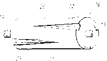
As shown in Figure 3, the spool 10 that is arranged in control cock 7 has six roads at spool 10 surperficial axially extended cone tanks 20,21,22,23.Twice groove (not shown) is positioned at the back side of spool 10 in addition.Last groove 20 stretches out from valve body 10 left sides, but does not extend to the right side.Following groove 21 stretches out from valve body 10 right sides, but does not extend to the left side.Groove 22 is forming with the same mode of groove 21, but its width narrows down gradually and shoals when groove 22 extends left.In addition, groove 23 forms in the mode identical with groove 20, but its width narrows down gradually and shoals when groove 23 extends to the right.
Introduce the effect of pneumatic control valve 7 now.
When left tire 3a and right tire 3b leaked gas, the air pressure of two tires was identical.Therefore, as shown in Figure 2, spool 10 is positioned at the central part of valve body 9, because its left and right sides pressurized equates.In this case, spool 10 is lip-deep to comprise that 20 to 23 six road grooves do not extend the space 9a in the valve body 9,9b, thereby two tire 3a, and the passage between the 3b has just been stopped up effectively.
But when tire 3b began to leak gas, as shown in Figure 4, spool 10 was pushed from right to left, because the air pressure among the normal tire 3a is than the height among the gas leakage tire 3b.In this case, groove 21,22 and the in addition a groove that is positioned at spool 10 back sides are forced to be communicated with the left part space 9b of valve body 9, thereby the air among the right tire 3a flows into left tire 3b gradually, and two tire 3a, and 3b is recessed flat.Like this, the driver just can easily perceive gas leakage.
When tire 3b breaks rapidly and recessed flat when going down, two tire 3a, the draught head among the 3b increase causes spool 10 to move significantly left, as shown in Figure 5.In this case, the flange 16 on the right-hand member elongated rods 14 combines with projection 17, thus enclosure space 9a.Then, the air pressure among the normal tire 3a slightly reduces, and the driver just can perceive tire and split generation.Because the gas leakage of tire 3a is slight, so car still can travel.
As shown in Figure 6, joint 5 comprises two separate piece, i.e. main part 30 and annex 31, and they can be the two ends of pneumatic control valve 7 and two tire 3a, and the internal connection of 3b gets up.Be fixed on cover 32 on the main part 31 by slip, main part 30 can be connected to each other or separate with annex 31, shown in arrow among Fig. 6.Therefore, just can remove long and short dash line part among Fig. 2 with finger manipulation cover 32 simply, promptly gas flow tube 8.When it was removed, the passage of main part 30 just had been disconnected, thereby right tire 3a and left tire 3b just are not connected each other.If the driver is because tire 3a, the air pressure among the 3b reduces and discovers and gas leakage, and he or she just can stop immediately, and removes gas flow tube 8 by operating joint 5,5.So just can prevent normal tire 3a gas leakage, replace gas leakage tire 3b with a new tyre then.
According to the present invention, two tire 3a, the air-flow between the 3b are pre certain suitable amount, and this will be described herein-after.
For example, if tire 3b breaks, suppose two tire 3a, 3b has been full of the air of 10 units, and the air among the gas leakage tire 3b is just with the per hour speed leakage of 2 units.Traditional many tires according to not intercommunication, shown in the air-flow scheme drawing, the air among the tire 3b is just with the per hour speed leakage of 2 units, but tire 3a is still normally, be not subjected to the influence of tire 3b, so the driver can continue to drive and not perceive the gas leakage of tire 3b at all.Yet, when driver's at high speed crosses bend, still have the danger that major accident takes place.
In order to solve this danger, the invention provides and a kind ofly can make two tire 3a, the gas flow tube 8 of air in certain amount circulation is arranged between the 3b, when tire 3b broke, the air among the normal tire 3a was supplied with gas leakage tire 3b, thus two tire 3a, amount of air among the 3b reduces with the identical speed of cardinal principle, as shown in Figure 8.In other words, two tires are all equally recessed flat, just look like to be one to have a flat tire the same.Therefore, the driver can avoid above-mentioned danger by Reduced Speed Now a period of time.Yet the driver still is difficult for having discovered which rupture of tire.When the tire 3b that breaks is changed by a new tyre, still there is a problem, promptly tire 3a also needs inflation.
In order to overcome this problem, preferably predetermined than the little of tire 3b of breaking the air leakage of tire 3a, thus a tire is slow after making the recessed flat advance ratio of previous tire.Fig. 9 is the scheme drawing that leaks gas gradually.Like this, as shown in this figure, the driver is by the normal tire 3a longer relatively stretch that can travel.In this case, tire 3a is recessed gradually flat, thereby makes the driver just perceive gas leakage before the major accident of above being discussed takes place.
In order to learn gas leakage gradually as shown in Figure 9, two tire 3a, the rate of air flow between the 3b preferably are predefined in per minute 0.01 and rise between 12 liters of the per minutes.Certainly, above-mentioned predetermined value can be regulated according to parts 5,6,7 diameter and groove 20 to 23 shape or the degree of depth separately separately of spool 10.
In order to allow the driver perceive two tire 3a at once, which has broken among the 3b, and the lamp 40,41 of two different colours of describing as long and short dash line can be installed at the outside face of wheel 1.For example, when tire 3b broke or leaks gas, first lamp 40 (such as taking on a red color) just lighted, and when tire 3a broke or leaks gas, second lamp 41 (such as being green) just lighted, and like this, which rupture of tire the driver just can easily perceive with naked eyes.Lamp 40,41 can be connected by the transfer device in the spool 10 that is contained in control cock 7.
More precisely, there are a plurality of electrodes 45 to 48 at the two ends of the inner edge 7a of control cock 7, and spool 10 can slide on this inner edge.In addition, two ring-type electric conductors 49,50 are arranged on the surface of spool 10.In this case, control cock 7 and spool 10 should be made by insulating material, as resin or materials similar.As two tire 3a, when some difference took place the air pressure between the 3b, spool 10 moved to the left or to the right, thereby electrode 45,46 just connects with conductor 49 or electrode 47,48 is connected with conductor 50.Then, a light-emitting diode that is arranged in the lamp 40,41 on Figure 11 circuit just has been switched on.After that, even the still scheduled maintenance of the lamp of this light yellow ON state has been moved in the position of spool 10.Numeral 52 is represented a battery, and numeral 53 is represented regularly quartz conductor, and numeral 54,55 representatives are used for keeping the quartz conductor of certain state.
Certainly, the present invention is not limited to the single-wheel twins, and can promote the use of three or more tires, and they can reach same purpose and effect.
As discussed above, when breaking rapidly for one in two or more tires, the air pressure of another tire is owing to the venting process of the tire that breaks also can reduce.Therefore, the driver can perceive gas leakage in the general-utility car with one group of single tire.
When two or more tires slowly leak gas, provide air by another normal tire, the air pressure of each tire will be tending towards identical thus.Like this, just can do low speed driving to a certain degree.Therefore, the driver just can avoid also needn't stopping owing to not perceiving any major accident that tire flat takes place fully.In addition, because of a plurality of tires are arranged, the driver can enjoy pulsation-free and drive, and good drainage performance.Also have, because pneumatic control valve is according to the gas leakage situation or open or close, so many tires can obtain safe protection.
The contrast accompanying drawing has been introduced most preferred embodiment of the present invention above, but should be pointed out that the present invention is not limited only to these specific embodiments, and those skilled in the art can carry out various changes and modification in the scope of claim of the present invention or spirit.
Claims (6)
1. wheel that a plurality of tires can be installed, it comprises: a plurality of wheel rims and a plurality of tires that have control cock that are arranged on each corresponding wheel rim, the inner space of its each adjacent tires interconnects by a gas flow tube, described gas flow tube comprises a pneumatic control valve, when the air pressure of each tire in described many tires equates, described control cock is closed, when the draught head between each tire of many tires surpasses a predetermined value, described control cock is opened, when described draught head increases, until reaching certain predetermined value, described control cock is closed; It is characterized in that described control cock comprises:
One in cylinder valve spool in axial sliding;
A pair ofly be used for left-hand, dextrad push away described spool with the pressure that equates spring;
Described two springs have two elongated rods that stretched out by valve swallow two ends, and described elongated rods has a flange in its termination; And
Described flange matches with the projection that forms at described valve interior wall, in order to stop up the air by-pass passage of described gas flow tube.
2. the wheel that a plurality of tires are installed as claimed in claim 1 is characterized in that, described gas flow tube can be pulled down from each tire.
3. the wheel that a plurality of tires are installed as claimed in claim 1 is characterized in that, one group of electric light is equipped with in the outside of described single-wheel, and lamp is just lighted when described control cock is turned on.
4. the wheel that a plurality of tires are installed as claimed in claim 1, it is characterized in that, described spool is cylindrical and have multiple tracks cone tank separated by a distance at described cylinder valve wicking surface, and the per pass groove extends to the other end by an end of described spool, but does not arrive the other end.
5. the wheel that a plurality of tires are installed as claimed in claim 1 is characterized in that described pneumatic control valve and spool are made by insulating material.
6. the wheel that a plurality of tires are installed as claimed in claim 1 is characterized in that, has a plurality of electrodes to be positioned at the two ends of described control cock inner edge, and on spool one edge a pair of ring-shaped conductor is arranged.
Applications Claiming Priority (3)
| Application Number | Priority Date | Filing Date | Title |
|---|---|---|---|
| JP17430891A JPH0579894A (en) | 1991-06-18 | 1991-06-18 | Measuring apparatus and measuring method |
| JP174308/91 | 1991-06-18 | ||
| JP174303/91 | 1991-06-18 |
Publications (2)
| Publication Number | Publication Date |
|---|---|
| CN1073140A CN1073140A (en) | 1993-06-16 |
| CN1034485C true CN1034485C (en) | 1997-04-09 |
Family
ID=15976388
Family Applications (1)
| Application Number | Title | Priority Date | Filing Date |
|---|---|---|---|
| CN 92104539 Expired - Fee Related CN1034485C (en) | 1991-06-18 | 1992-06-08 | Multi-tyre on single wheel |
Country Status (2)
| Country | Link |
|---|---|
| JP (1) | JPH0579894A (en) |
| CN (1) | CN1034485C (en) |
Families Citing this family (3)
| Publication number | Priority date | Publication date | Assignee | Title |
|---|---|---|---|---|
| CN104070922A (en) * | 2014-06-27 | 2014-10-01 | 曾海 | Automobile wheel |
| CN104527338B (en) * | 2014-12-25 | 2018-03-09 | 许鑫新 | It is easy to the tire construction and Self-Balancing vehicle turned |
| CN106183638A (en) * | 2016-07-07 | 2016-12-07 | 郭晓宇 | A kind of vehicle explosion-proof balance tire |
-
1991
- 1991-06-18 JP JP17430891A patent/JPH0579894A/en active Pending
-
1992
- 1992-06-08 CN CN 92104539 patent/CN1034485C/en not_active Expired - Fee Related
Also Published As
| Publication number | Publication date |
|---|---|
| CN1073140A (en) | 1993-06-16 |
| JPH0579894A (en) | 1993-03-30 |
Similar Documents
| Publication | Publication Date | Title |
|---|---|---|
| CN1034485C (en) | Multi-tyre on single wheel | |
| US5244026A (en) | Multiple tires on a single wheel | |
| EP0081468A2 (en) | Safety inner tube for motor vehicles | |
| CN103112322B (en) | For the device of self-equalizing tire pressure in vehicle traveling process | |
| CN105082872A (en) | Novel wheel | |
| CN2892529Y (en) | Four tyre heel double-chamber tyre | |
| CN2880551Y (en) | Multiple air cavity tyre | |
| CN106739815A (en) | A kind of trouble-proof tire | |
| CN106183638A (en) | A kind of vehicle explosion-proof balance tire | |
| CN2389078Y (en) | Multi-inner tube type explosion free tyre | |
| CN100389972C (en) | Four-bead heel double-cavity tyre | |
| CN2678933Y (en) | Anti-prizing and anti-breaking inner tube of motor vehicle | |
| CN2399237Y (en) | Safety wheel of motor vehicle | |
| CN2789059Y (en) | Tyre with double-inner tube | |
| CN2561612Y (en) | Safety tyre with multiple air cavities | |
| CN204526657U (en) | Double-tube tire | |
| CN1309036A (en) | Mutual spare inflatable tyre and its rim | |
| KR940019504A (en) | Passenger car tires with high speed performance | |
| RU2086420C1 (en) | Tyre for vehicle running gear | |
| CN108638760B (en) | Traction steel rope type anti-tire-burst rollover-prevention tire structure | |
| CN2415950Y (en) | Mutual spare inflatable tyre and its rim | |
| CN208602243U (en) | Explosion-proof anti-tie air leak preventing tyre | |
| CN207000062U (en) | A kind of trouble-proof tire | |
| US20070240802A1 (en) | Run-flat tire having multiple chambers | |
| CN2376392Y (en) | Multi-chamber type inflated inner tube |
Legal Events
| Date | Code | Title | Description |
|---|---|---|---|
| C06 | Publication | ||
| PB01 | Publication | ||
| C10 | Entry into substantive examination | ||
| SE01 | Entry into force of request for substantive examination | ||
| C14 | Grant of patent or utility model | ||
| GR01 | Patent grant | ||
| C15 | Extension of patent right duration from 15 to 20 years for appl. with date before 31.12.1992 and still valid on 11.12.2001 (patent law change 1993) | ||
| OR01 | Other related matters | ||
| C19 | Lapse of patent right due to non-payment of the annual fee | ||
| CF01 | Termination of patent right due to non-payment of annual fee |