CN103473757A - Object tracking method in disparity map and system thereof - Google Patents
Object tracking method in disparity map and system thereof Download PDFInfo
- Publication number
- CN103473757A CN103473757A CN2012101886612A CN201210188661A CN103473757A CN 103473757 A CN103473757 A CN 103473757A CN 2012101886612 A CN2012101886612 A CN 2012101886612A CN 201210188661 A CN201210188661 A CN 201210188661A CN 103473757 A CN103473757 A CN 103473757A
- Authority
- CN
- China
- Prior art keywords
- detected object
- detected
- disparity map
- estimating
- frame
- Prior art date
- Legal status (The legal status is an assumption and is not a legal conclusion. Google has not performed a legal analysis and makes no representation as to the accuracy of the status listed.)
- Granted
Links
- 238000000034 method Methods 0.000 title claims abstract description 72
- 238000001514 detection method Methods 0.000 claims abstract description 50
- 230000008878 coupling Effects 0.000 claims description 35
- 238000010168 coupling process Methods 0.000 claims description 35
- 238000005859 coupling reaction Methods 0.000 claims description 35
- 230000008569 process Effects 0.000 claims description 12
- 238000006243 chemical reaction Methods 0.000 claims description 7
- 238000010586 diagram Methods 0.000 description 19
- 238000006073 displacement reaction Methods 0.000 description 16
- 238000005516 engineering process Methods 0.000 description 7
- 239000011295 pitch Substances 0.000 description 7
- 230000000295 complement effect Effects 0.000 description 5
- 230000001915 proofreading effect Effects 0.000 description 5
- 230000000007 visual effect Effects 0.000 description 4
- 238000003745 diagnosis Methods 0.000 description 3
- 238000012544 monitoring process Methods 0.000 description 3
- 238000004458 analytical method Methods 0.000 description 2
- 230000008901 benefit Effects 0.000 description 2
- 230000008859 change Effects 0.000 description 2
- 238000012937 correction Methods 0.000 description 2
- 230000000694 effects Effects 0.000 description 2
- 238000003384 imaging method Methods 0.000 description 2
- 238000012986 modification Methods 0.000 description 2
- 230000004048 modification Effects 0.000 description 2
- 238000012545 processing Methods 0.000 description 2
- 238000011160 research Methods 0.000 description 2
- 239000007787 solid Substances 0.000 description 2
- 241000931705 Cicada Species 0.000 description 1
- 239000000654 additive Substances 0.000 description 1
- 230000000996 additive effect Effects 0.000 description 1
- 230000015572 biosynthetic process Effects 0.000 description 1
- 238000012512 characterization method Methods 0.000 description 1
- 230000001186 cumulative effect Effects 0.000 description 1
- 238000013461 design Methods 0.000 description 1
- 238000011161 development Methods 0.000 description 1
- 238000005259 measurement Methods 0.000 description 1
- 230000008447 perception Effects 0.000 description 1
- 230000003068 static effect Effects 0.000 description 1
Images






Landscapes
- Image Analysis (AREA)
- Traffic Control Systems (AREA)
Abstract
An object tracking method and a system thereof are provided. The method comprises the following steps that a first detection object in a first disparity map is detected and a position of the first detection object is obtained; the position of the first detection object is converted into a first-detection relative position based on a coordinate of a first predetermined reference point in the first disparity map; based on the first-detection relative position, and a predetermined motion direction and a predetermined motion speed of the first detection object, an estimation position of a first estimation object corresponding to the first detection object in a second disparity map is estimated; a second detection object in the second disparity map is detected and a position of the second detection object is acquired; the position of the second detection object is converted into a second-detection relative position based on a coordinate of a second predetermined reference point in the second disparity map; based on the estimation position of the first estimation object and the second-detection relative position of the second detection object, a tracking and matching relation between the first detection object and the second detection object is determined.
Description
Technical field
The present invention relates to image processing field, and more specifically, relate to a kind of method for tracing object and system in disparity map.
Background technology
Now, the stereo-picture technology is an important branch of computer vision, it can obtain neatly the Stereo Vision of scenery, especially binocular vision information under multiple condition, monocular image has incomparable advantage relatively, is the forward position research direction of image processing and computer vision field.Particularly, for example, by steric information, such as disparity map, (carry out object, car on road, people etc.) follow the tracks of, also traffic monitoring, the auxiliary driving, the automobile detection and tracking, there are very important practical value and vast potential for future development in the fields such as alarm drive system, robot visual guidance, industrial products detection, medical diagnosis, virtual reality.
The ultimate principle of stereoscopic vision is to observe same scenery from two (or a plurality of) viewpoints, to obtain the perceptual image under different visual angles, obtain the 3 D stereo information of scenery by the position deviation between principle of triangulation computed image pixel (parallax (disparity)).The three-dimensional perception of this process and human vision is similar.Usually, for example with two of left and right video camera, carry out the 3 D stereo information of any point in measurement environment or an object, thereby obtain disparity map.
Disparity map is for example, image to the difference formation of the horizontal ordinate of the corresponding point of (image that the image that, left video camera is taken and right video camera are taken) with the left and right image.Certainly, in this area, there are many additive methods to obtain disparity map, are not repeated herein.Range information because disparity map has comprised scene, therefore carry out a series of application, particularly carry out image tracing based on disparity map, is field the most active in binocular vision research always.
In prior art, proposed to utilize disparity map to carry out the certain methods of tracing object.
For example, on September 22nd, 2011 disclosed U.S. Patent application US 2011228100 A1(be entitled as " Object Tracking Device and Method of Controlling Operation of the Same ") in a kind of object tracking technique is disclosed.Generate the disparity map of the parallax of each pixel that shows this object in the three dimensional object image that its two imaging devices installing from for example vehicle are taken, determine sensing range, in order to eliminate on depth direction other objects in tracing object, for example pedestrian front from the disparity map generated, then detect tracing object, for example pedestrian in definite sensing range, like this, can prevent from detecting the people by bike who is positioned at tracing object, for example pedestrian front.But, this technology has only been considered the sensing range (be the scope of distance object and imaging device between) of how to confirm tracing object on depth direction, but this technology is not considered to take when the left and right vehicle wheel of disparity map is turned or vehicle pitches the impact on tracing object.
In addition, the U.S. Pat 7974442B2(on July 5th, 2011 bulletin is entitled as " Vehicular Vision System ") in a kind of vehicle vision system near the object (target) identification and classifying vehicle is disclosed.This system comprises and producing in order to generate near the sensor array of the image of the depth map of scene vehicle, process this depth map and by its with vehicle near the template presented in advance of the destination object that may occur compare, be complementary to produce object listing by template and this depth map that will present in advance, this system is processed this object listing and is produced target sizes and classification assessment, then, when this vehicle mobile of this gtoal setting, follow the tracks of this target, and the position of definite target, classification and speed.This patent is only come to compare with depth map by the template that presents in advance, when the left and right vehicle wheel of also not considering to take disparity map is turned or vehicle pitches on the impact of tracing object.
Yet, in the Vehicle Driving Cycle process of taking disparity map, always may produce some problems affects the shooting of disparity map and the tracking of object.For example, at the turn inside diameter that loads binocular camera or produces because road surface is uneven while jolting, even this object with respect to the invariant position of this vehicle, the picture position of the object showed in captured disparity map is also possible, and great changes will take place.In this case, the technology proposed in prior art can not be followed the tracks of this object more accurately.
Therefore, need to a kind ofly based on disparity map, carry out the method and system of tracing object exactly.
Summary of the invention
In order to address the above problem, according to an aspect of the present invention, a kind of method for tracing object in disparity map is provided, comprises the following steps: the first detecting step, detect one or more the first detected objects in the first disparity map and obtain the position of each the first detected object; The first switch process, each of coordinate that the position of each the first detected object is converted to the first predetermined reference point based in the first disparity map first detects relative position; Estimate step, based on each the first pre-motion orientation and predetermined movement velocity that detects relative position and each the first detected object, estimate in the second disparity map each first position of estimating of estimating object corresponding to each the first detected object; The second detecting step, detect one or more the second detected objects in the second disparity map and obtain the position of each the second detected object; The second switch process, each of coordinate that the position of each the second detected object is converted to the second predetermined reference point based in the second disparity map second detects relative position; Determining step, detect relative position based on each first second of position and described each second detected object of estimating of estimating object, determine with each and first estimate each first detected object that object is corresponding and the tracking and matching relation between each the second detected object.
Preferably, the coordinate of described the first predetermined reference point can be included in the horizontal ordinate of end point of the road in the first disparity map and at least one in ordinate, and the coordinate of described the second predetermined reference point is included in the horizontal ordinate of end point of the same road in the second disparity map and at least one in ordinate.
Preferably, described the first detecting step can also obtain the size of each the first detected object, and wherein, the size of each the first detected object is as each the first size of estimating object, and the second detecting step also obtains the size of each the second detected object.
Preferably, described determining step can detect relative position and size based on each the first second of position and size and each the second detected object of estimating of estimating object, and determines the tracking and matching relation between each first detected object and each the second detected object.
Preferably, described determining step can comprise the following steps: based on each first second of position and size and described each second detected object of estimating of estimating object, detect relative position and size, first estimate object for each, calculate each and first estimate object and each the second detected object overlapping area on surface level; If one first is estimated one of object and second detected object overlapping area maximum on described surface level, determine with this and first estimate one of the first detected object that object is corresponding and described second detected object and mate.
Preferably, described determining step can also comprise the following steps: if one first estimate object and more than two the second detected object overlapping area on described surface level all maximum, calculate this and first estimate object and the second detected object overlapping area on depth plane more than two; If this first estimates object and described one of second detected object overlapping area maximum on depth plane more than two, determine with this first estimate the first detected object that object is corresponding and described more than two one of second detected object mate.
Preferably, described determining step can also comprise the following steps: each described first minor increment of estimating between the second detection relative position of estimating position and each the second detected object of coupling not of object of calculating coupling not; If the minor increment of this calculating is less than predetermined threshold, determines with this first the second detected object of estimating the first detected object that object is corresponding and thering is minor increment and mate.
Preferably, described predetermined threshold can be based on and determine with the described first maximum movement speed of estimating the first detected object that object is corresponding.
Preferably, described determining step can also comprise the following steps: if first detected object does not mate with any the second detected object, determine that this first detected object disappears in the second disparity map, if and second detected object with any the first detected object coupling, determine that this second detected object is new object in the second disparity map.
Preferably, in the method, after the tracking and matching relation of determining between each first detected object and each the second detected object, first-phase that can be based on each the first detected object to detection position and with the second-phase of each the second detected object of its coupling to detection position, proofread and correct pre-motion orientation and the predetermined movement velocity of each the first detected object, as pre-motion orientation and the predetermined movement velocity of each the second detected object with its coupling.
According to a further aspect in the invention, provide a kind of object-tracking systems in disparity map, comprising: the first pick-up unit, detect one or more the first detected objects in the first disparity map and obtain the position of each the first detected object; The first conversion equipment, each of coordinate that the position of each the first detected object is converted to the first predetermined reference point based in the first disparity map first detects relative position; Estimating device, based on each the first pre-motion orientation and predetermined movement velocity that detects relative position and each the first detected object, estimate in the second disparity map each first position of estimating of estimating object corresponding to each the first detected object; Second detection device, detect one or more the second detected objects in the second disparity map and obtain the position of each the second detected object; The second conversion equipment, each of coordinate that the position of each the second detected object is converted to the second predetermined reference point based in the second disparity map second detects relative position; Determine device, detect relative position based on each first second of position and described each second detected object of estimating of estimating object, determine with each and first estimate each first detected object that object is corresponding and the tracking and matching relation between each the second detected object.
By technical scheme of the present disclosure, can carry out tracing object more accurately based on disparity map.
The accompanying drawing explanation
Only by example, describe the preferred embodiments of the present invention referring now to accompanying drawing, above-mentioned and other purpose of the present disclosure, Characteristics and advantages will become more obvious, in the accompanying drawings:
Fig. 1 exemplarily illustrates the schematic diagram of putting into practice example vehicle system of the present invention;
Fig. 2 is the schematic diagram of variation that exemplarily is illustrated in turn inside diameter or produces the picture position of the object showed in the captured disparity map obtained while jolting because road surface is uneven;
Fig. 3 is the process flow diagram that the method for tracing object in disparity map according to an embodiment of the invention exemplarily is shown;
Fig. 4 is the block scheme that the object-tracking systems in disparity map according to another embodiment of the invention exemplarily is shown;
Fig. 5 (a)-5 (c) exemplarily shows respectively binocular camera and takes at t-1 frame, t frame, t+1 frame disparity map and the gray-scale map obtained respectively;
Fig. 6 (a)-6 (d) exemplarily shows the schematic diagram that in the t-1 frame, the subject area detected is converted to the subject area based on the road end point;
Fig. 7 exemplarily illustrates the subject area based on the road end point in the t frame of estimating according to the subject area based on the road end point in the t-1 frame;
Fig. 8 (a)-(d) exemplarily shows the schematic diagram that in the t frame, the subject area detected is converted to the subject area based on the road end point;
Fig. 9 (a) and (b) be the schematic diagram that exemplarily is illustrated in two methods using when the tracking and matching of determining between each object detected in each object of detecting in the t-1 frame and t frame concerns;
Figure 10 (a)-(c) is the schematic diagram of the other method when exemplarily being illustrated in the tracking and matching of determining between each object detected in each object of detecting in the t-1 frame and t frame and concerning;
Figure 11 (a)-(b) is the schematic diagram in zone that exemplarily is illustrated in the object of the coupling of determining that the tracking and matching relation between each object detected in each object of detecting in the t-1 frame and t frame obtains afterwards;
Figure 12 exemplarily illustrates the preset movement distance of proofreading and correct each object detected in the t-1 frame, as the preset movement distance of each object detected in the t frame with its coupling; And
Figure 13 (a)-(e) exemplarily illustrates the preset distance utilized after proofreading and correct the t+1 frame to be determined to the schematic diagram of tracking and matching relation.
Embodiment
Preferred implementation of the present disclosure is described below with reference to accompanying drawings in more detail.Although shown preferred implementation of the present disclosure in accompanying drawing, yet should be appreciated that, can realize the disclosure and the embodiment that should do not set forth limits here with various forms.On the contrary, it is in order to make the disclosure more thorough and complete that these embodiments are provided, and those skilled in the art can having read the disclosure after, know the disclosure in not description other embodiments also within the scope of the present disclosure.
Fig. 1 exemplarily illustrates the schematic diagram of putting into practice example vehicle system of the present invention.
In Fig. 1, for example on vehicle, binocular camera is being installed, in order to take (example as shown in Figure 1) left image and right image in the Vehicle Driving Cycle process.Generate disparity map from captured left image and right image.At this, the mode that generates disparity map from captured left image and right image is well known to a person skilled in the art, does not therefore repeat.Thereby, the interval schedule time is (for example, in the situation that 25 frames/second, 1/25 second, interval) carry out this shooting, make in two or more disparity map input processors that will generate, determine for example, the tracking and matching relations during this schedule time (1/25 second) of object such as pedestrian on road or vehicle, determine whether the objects such as pedestrian on road or vehicle for example, still can trace into afterwards in this schedule time (1/25 second).
Certainly, on vehicle, application method for tracing object of the present invention and system are only examples of example, based on actual demand, for example traffic monitoring, robot visual guidance, industrial products detection, medical diagnosis, virtual reality etc., can also on other objects, apply method for tracing object of the present invention and system to reach the purpose to image tracing and location.
Fig. 2 is the schematic diagram of variation that exemplarily is illustrated in turn inside diameter or produces the picture position of the object showed in the captured disparity map obtained while jolting because road surface is uneven.
As what set forth in background technology, in reality, such a case may occur: great variety can occur in the picture position that produces the object showed in the captured disparity map obtained while jolting at turn inside diameter or because road surface is uneven.As shown in Figure 2, the top of Fig. 2 shows the disparity map of present frame, suppose to follow the tracks of to as if the part that circle enclosed of upper left-hand.When vehicle bends to right, see the bottom of Fig. 2, can see, the object of tracking has been offset certain distance left.In this case, in prior art, proposition utilizes the technology of the degree of depth of object can not follow the tracks of exactly this object.
Embodiment of the present disclosure also can realize good object tracking effect in these cases.
Fig. 3 is the process flow diagram that the method for tracing object 300 in disparity map according to an embodiment of the invention exemplarily is shown.
This method for tracing object 300 comprises: the first detecting step (S301), detect one or more the first detected objects in the first disparity map and obtain the position of each the first detected object; The first switch process (S302), each of coordinate that the position of each the first detected object is converted to the first predetermined reference point based in the first disparity map first detects relative position; Estimate step (S303), based on each the first pre-motion orientation and predetermined movement velocity that detects relative position and each the first detected object, estimate in the second disparity map each first position of estimating of estimating object corresponding to each the first detected object; The second detecting step (S304), detect one or more the second detected objects in the second disparity map and obtain the position of each the second detected object; The second switch process (S305), each of coordinate that the position of each the second detected object is converted to the second predetermined reference point based in the second disparity map second detects relative position; Determining step (S306), detect relative position based on each first second of position and described each second detected object of estimating of estimating object, determine with each and first estimate each first detected object that object is corresponding and the tracking and matching relation between each the second detected object.
In one embodiment, described determining step can also comprise the following steps: each described first minor increment of estimating between the second detection relative position of estimating position and each the second detected object of coupling not of object of calculating coupling not; If the minor increment of this calculating is less than predetermined threshold, determines with this first the second detected object of estimating the first detected object that object is corresponding and thering is minor increment and mate.
For example, usually suppose that for example tracing object for example is 60km/h(to the maximum with the relative travel speed of the vehicle that binocular camera for example is installed, in indicating the track of 60-120km/h), for example, in predetermined time interval (1/25 second), be multiplied by the time interval by maximal rate, can obtain the ultimate range that tracing object advances with respect to vehicle during this period and be about 6 meters.In this case, can be set to 6 meters by above-mentioned predetermined threshold.So, if the distance of estimating between object and detected object is greater than 6 meters, the probability of estimating object and detected object and be the tracing object mated is just minimum, can think that both are unmatched.If, and the distance of estimating between object and detected object is less than 6 meters, can think that both mate.
Certainly, above-mentioned predetermined threshold is not limited to by maximal phase, travel speed be arranged, and it also can arrange by empirical value, also can arrange by statistics, etc., the disclosure is not limited to this.
The first predetermined reference point and the second predetermined reference point in the second disparity map in above-mentioned the first disparity map can be interrelated, and can indicate the Same Physical implication.For example, this first predetermined reference point and the second predetermined reference point can be but be not limited to the end point of road, and it can also be other points with same physical implication, such as point of the sun etc.
In one embodiment, the coordinate of described the first predetermined reference point can be included in the horizontal ordinate of end point of the road in the first disparity map and at least one in ordinate, and the coordinate of described the second predetermined reference point is included in the horizontal ordinate of end point of the same road in the second disparity map and at least one in ordinate.
That is to say, while considering this first predetermined reference point or the second predetermined reference point, having more than is the complete exact position of considering them.For example, in the situation that mainly consider that for example turn in the left and right of vehicle, the horizontal ordinate of the position of these predetermined reference point is by even more important, and can only use the horizontal ordinate of the position of these predetermined reference point, and in like manner, in the situation that mainly consider for example pitching of vehicle, the ordinate of the position of these predetermined reference point is by even more important, and can only use the ordinate of the position of these predetermined reference point, in like manner, in the situation that consider to turn and to pitch etc. such as the left and right of vehicle, both can use horizontal ordinate and the ordinate of the position of these predetermined reference point simultaneously.
Be converted to respectively the disparity map based on these two predetermined reference point taking the name a person for a particular job disparity map of twice shooting of two predetermined reference in the residing situation of disparity map based on be separated by certain hour interval and twice, make when definite object tracking relationship, can eliminate the left and right turning of vehicle and/or the bias effect that pitches the disparity map of taking is caused.
In one embodiment, described the first detecting step can also obtain the size of each the first detected object, wherein, the size of each the first detected object is as each the first size of estimating object, and the second detecting step also obtains the size of each the second detected object.
For example, such size can comprise wide, high, the degree of depth of object, indicates three-dimensional size.
In one embodiment, described determining step can detect relative position and size based on each the first second of position and size and each the second detected object of estimating of estimating object, and determines the tracking and matching relation between each first detected object and each the second detected object.
If the size of object, also as a condition determining object tracking and matching relation, can be determined to whether object mates more accurately.
In one embodiment, described determining step can comprise the following steps: based on each first second of position and size and described each second detected object of estimating of estimating object, detect relative position and size, first estimate object for each, calculate each and first estimate object and each the second detected object overlapping area on surface level; If one first is estimated one of object and second detected object overlapping area maximum on described surface level, determine with this and first estimate one of the first detected object that object is corresponding and described second detected object and mate.
Calculate each and first estimate object and each the second detected object overlapping area on surface level and can mean width and the degree of depth of only considering each object, and do not consider the height of object.
In one embodiment, described determining step can also comprise the following steps: if one first estimate object and more than two the second detected object overlapping area on described surface level all maximum, calculate this and first estimate object and the second detected object overlapping area on depth plane more than two; If this first estimates object and described one of second detected object overlapping area maximum on depth plane more than two, determine with this first estimate the first detected object that object is corresponding and described more than two one of second detected object mate.
Calculate each and first estimate object and each the second detected object overlapping area on depth plane and can mean width and the height of only considering each object, and do not consider the degree of depth of object.
In one embodiment, described determining step can also comprise the following steps: each described first minor increment of estimating between the second detection relative position of estimating position and each the second detected object of coupling not of object of calculating coupling not; If the minor increment of this calculating is less than predetermined threshold, determines with this first the second detected object of estimating the first detected object that object is corresponding and thering is minor increment and mate.
Now, can, in the situation that the overlapping area of calculated level face and depth plane does not still find match objects after determining the step of object matching, carry out following steps.
For example, usually suppose that for example tracing object for example is 60km/h(to the maximum with the relative travel speed of the vehicle that binocular camera for example is installed, in indicating the track of 60-120km/h), for example, in predetermined time interval (1/25 second), be multiplied by the time interval by maximal rate, can obtain the ultimate range that tracing object advances with respect to vehicle during this period and be about 6 meters.In this case, can be set to 6 meters by above-mentioned predetermined threshold.So, if the distance of estimating between object and detected object is greater than 6 meters, the probability of estimating object and detected object and be the tracing object mated is just minimum, can think that both are unmatched.If, and the distance of estimating between object and detected object is less than 6 meters, can think that both mate.
That is to say, in one embodiment, described predetermined threshold can be based on to be determined with the described first maximum movement speed of estimating the first detected object that object is corresponding.
At this, movement velocity, direction of motion, displacement that it is pointed out that the object of mentioning herein etc. is all for example, speed of related movement, direction of motion, displacement with respect to the object for taking disparity map (binocular camera).
In one embodiment, described determining step can also comprise the following steps: if first detected object does not mate with any the second detected object, determine that this first detected object disappears in the second disparity map, if and second detected object with any the first detected object coupling, determine that this second detected object is new object in the second disparity map.
Like this, can show that the existing object in the first disparity map of which object matching in the second disparity map has traced into existing object in the first disparity map in the second disparity map; Which object in the second disparity map does not mate existing object in the first disparity map, and these are to liking emerging object in the second disparity map; In the first disparity map, existing which object does not mate in the second disparity map, and these objects have disappeared in the second disparity map.
In one embodiment, in the method, after the tracking and matching relation of determining between each first detected object and each the second detected object, first-phase that can be based on each the first detected object to detection position and with the second-phase of each the second detected object of its coupling to detection position, proofread and correct pre-motion orientation and the predetermined movement velocity of each the first detected object, as pre-motion orientation and the predetermined movement velocity of each the second detected object with its coupling.
Like this, by each object in cicada the first disparity map and the matching relationship of each object in the second disparity map, the object that can learn each coupling during this predetermined time interval with respect to the vehicle that binocular camera for example is installed and mobile distance, can proofread and correct direction of motion and the movement velocity of the object of each coupling, so that direction of motion and movement velocity with this correction during next predetermined time interval are calculated the displacement of each object with respect to this vehicle, to estimate after next predetermined time interval each object with respect to the position of vehicle.So, can continue to follow the tracks of circularly each object during next predetermined time interval.
So, according to embodiments of the invention, can carry out image tracing exactly.
Fig. 4 is the block scheme that the object-tracking systems in disparity map 400 according to another embodiment of the invention exemplarily is shown.
This object-tracking systems 400 comprises: the first pick-up unit (401), detect one or more the first detected objects in the first disparity map and obtain the position of each the first detected object; The first conversion equipment (402), each of coordinate that the position of each the first detected object is converted to the first predetermined reference point based in the first disparity map first detects relative position; Estimating device (403), based on each the first pre-motion orientation and predetermined movement velocity that detects relative position and each the first detected object, estimate in the second disparity map each first position of estimating of estimating object corresponding to each the first detected object; Second detection device (404), detect one or more the second detected objects in the second disparity map and obtain the position of each the second detected object; The second conversion equipment (405), each of coordinate that the position of each the second detected object is converted to the second predetermined reference point based in the second disparity map second detects relative position; Determine device (406), detect relative position based on each first second of position and described each second detected object of estimating of estimating object, determine with each and first estimate each first detected object that object is corresponding and the tracking and matching relation between each the second detected object.
Certainly, this object-tracking systems 400 can also comprise with each other steps of above-mentioned method for tracing object 300 and installing one to one, is not repeated herein.
So, according to embodiments of the invention, can carry out image tracing exactly.
Illustrate in greater detail each step of method for tracing object of the present invention below with reference to an object lesson.
Fig. 5 (a)-5 (c) exemplarily shows respectively binocular camera and takes at t-1 frame, t frame, t+1 frame (the figure left side) disparity map and (the figure right side) gray-scale map obtained respectively.
The binocular camera of supposing to be arranged on vehicle for example, has been taken three frames, i.e. t-1 frame, t frame, t+1 frame continuously with predetermined time interval (1/25 second).Certainly, also can be taken by the different time intervals, the present invention does not limit this predetermined time interval, this predetermined time interval also can change, but for simplified characterization, suppose that this predetermined time interval fixes in the disclosure, therefore utilize the speed of related movement of object, the relative movement distance that direction can calculate object, with for estimate the position of object in next time interval, as described in detail later.
Next will describe in detail and how to mate and tracing object between t-1 frame, t frame, t+1 frame.
Fig. 6 (a)-6 (d) exemplarily shows the schematic diagram that in the t-1 frame, the subject area detected is converted to the subject area based on the road end point.
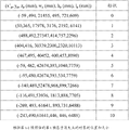
At first, Fig. 6 (a) exemplarily shows the subject area detected in the t-1 frame, sees the square frame sign in Fig. 6 (a).Identify respectively 11 objects of this detection with sign 1-10.
Herein, in the current unexposed patented claim that is entitled as " road method for checking object and system " that the application number that a kind of method in detected object zone can be submitted on November 18th, 2011 to Patent Office of the People's Republic of China in same Applicant in disparity map is 201110369183.0, find.At this, this patented claim is quoted and invested this.Certainly, those skilled in the art also can carry out detected object in the t-1 frame by the method for other or the following detected object that may occur.
Fig. 6 (b) exemplarily shows particular location and the size (x (pixel) in the zone of these 11 objects that detect in the t-1 frame, y (pixel), z (mm), w (mm), h (mm), l (mm)), wherein x, y represent horizontal ordinate and the ordinate of top left corner apex in the image of taking of this object, z represents the degree of depth of this object, the for example distance between binocular camera that this object and shooting are used, and w represents the width of this object, the height that h represents this object, l represents the degree of depth of this object itself.So, this x, y, z can represent the particular location of this object, and this w, h, l can represent the size of this object.
Note, in the present invention, can only with the particular location of object, be followed the tracks of, also can with particular location and the size both followed the tracks of (will specifically describe after a while), and be only for convenience of description in Fig. 6 (b) and understand, show particular location and both examples of size in the zone of these objects, but the invention is not restricted to this.
Particularly, for example the zone of object 0 is (391,494,21455,495,721,609), also just mean, the position of the top left corner apex of this object 0 is (x=391 (pixel), y=494 (pixel), z=21455 (mm)), and the size of this object is (w=495 (mm), h=721 (mm), l=609 (mm)).Certainly, only provided the position of top left corner apex of object in accompanying drawing of the present disclosure as the position of object, certainly, it may occur to persons skilled in the art that the central point that utilizes object, the position of other points of summit, the lower right corner etc. is also possible as the position of object.In addition, each particular location of object 1, object 2, object 3, object 4, object 5, object 6, object 7, object 8, object 9, object 10 and size, as shown in Fig. 6 (b), are not described one by one at this.
Fig. 6 (c) exemplarily shows the road end point in the t-1 frame.
As before described, be applied to not necessarily road end point of predetermined reference point in method of the present invention, and can be the point with other physical meaning, for example as a reference point etc. with the sun.
At this, the current unexposed patented claim that is entitled as " the road partage detection method based on parallax information " that to obtain application number that the method for road end point can submit on Dec 09th, 2011 to Patent Office of the People's Republic of China in same Applicant be 201110409269.1, and the Zhencheng Hu delivered on June 8th, 2005, Francisco Lamosa, being entitled as of Keiichi Uchimura " U-V-disparity:an efficient algorithm for stereovision based scene analysis " found in (ISBN:0-7695-2327-7), at this, these reference citations are invested to this.Certainly, those skilled in the art also can obtain by other or the following method that obtains the road end point that may occur horizontal ordinate or the ordinate of the road end point in the t-1 frame.
Fig. 6 (d) exemplarily shows the subject area will detected in the t-1 frame and is converted to the subject area based on this road end point.
As described above, in the situation that mainly consider that for example turn in the left and right of vehicle, the horizontal ordinate of the position of these predetermined reference point is by even more important, and can only use the horizontal ordinate of the position of these predetermined reference point, and in like manner, in the situation that mainly consider for example pitching of vehicle, the ordinate of the position of these predetermined reference point is by even more important, and can only use the ordinate of the position of these predetermined reference point, in like manner, in the situation that consider to turn and to pitch etc. such as the left and right of vehicle, both can use horizontal ordinate and the ordinate of the position of these predetermined reference point simultaneously.
Therefore, illustratively, at this, because the left and right turning phenomenon of vehicle is comparatively common and object offset distance that cause is larger, therefore in the disclosure, exemplarily only consider the horizontal ordinate of road end point.At this, the horizontal ordinate of the road end point that the patented claim that the application number that utilization is quoted is 201110409269.1 obtains is x
v=450 (pixel).(certainly, also can by the V-disparity map, (along the V coordinate direction in image coordinate system, obtain meaning the y coordinate of road end point, the value of the y that on the V-disparity map, Road is 0 o'clock in parallax value, be the ordinate of road end point.At this, the disclosure is only set forth as an example with the horizontal ordinate that obtains the road end point, but the disclosure is not limited to this.)
Can find out that from Fig. 6 (d) the horizontal ordinate x of each subject area by the detection by obtaining in Fig. 6 (b) deducts the horizontal ordinate x of road end point
v=450 (pixel) obtain each subject area based on this road end point (x ', y, z, w, h, l)=(x-x
v, y, z, w, h, l).Particularly, for example, for object 0, (391,494,21455,495,721,609) are deducted to x
v=450 (pixel) obtain (59,494,21455,495,721,609).
Certainly, in another embodiment, the invention is not restricted to only to consider that the horizontal ordinate of road end point eliminates the left and right skew of binocular camera, also can only consider that the ordinate of road end point eliminates the skew up and down of binocular camera, perhaps consider the horizontal ordinate of road end point and left and right skew and skew up and down that ordinate is eliminated binocular camera, those skilled in the art are the very clear ordinate considering the road end point also, perhaps consider in the situation of the horizontal ordinate of road end point and ordinate, how to obtain each subject area based on this road end point, be not repeated herein.
By being converted to the subject area based on the road end point, turning and/or pitch etc. the impact of the position of detected object in captured image in the left and right that can eliminate the vehicle that binocular camera is installed, thereby can contribute to determine more accurately object tracking and matching relation.
Fig. 7 exemplarily illustrates the subject area based on the road end point in the t frame of estimating according to the subject area based on the road end point in the t-1 frame.
If be scheduled to direction of motion and the movement velocity of each object in the t-1 frame, can extrapolate the displacement separately (Δ x, Δ y, Δ z) of each object on the x, y, z direction by the time interval of being separated by between t-1 frame and t frame.Wherein, this Δ x, Δ y, the arbitrary value in Δ z, for example Δ x get on the occasion of, the positive dirction that the direction of motion corresponding to object on the x axle is the x axle, and for example Δ x gets the negative value negative direction that the direction of motion on the x axle is the x axle corresponding to object.The direction of motion of these each objects and movement velocity can preset, and also can calculate by known manner, predict etc., are not repeated herein.In addition, at this, only described by predetermined direction of motion and movement velocity and calculated displacement, but also can be directly preset movement distance in an embodiment.In the disclosure, movement velocity and direction of motion can be used interchangeably with (get on the occasion of or negative value) displacement.
And, suppose that the size of the object based on the road end point in the t-1 frame is identical with the size of the object based on the road end point in the t frame of estimating, i.e. w
p=w, h
p=h, and l
p=l.
Therefore, the subject area based on the road end point in the t frame of estimating according to the subject area based on the road end point in the t-1 frame for (x '
p, y
p, z
p, w
p, h
p, l
p)=(x '+Δ x, y+ Δ y, z+ Δ z, w, h, l).
In the disclosure, to calculate and clearly set forth principle of the present invention in order to simplify, in the t-1 frame, pre-motion orientation and the movement velocity of each object are initialized as to (0,0,0), suppose when initial each to as if static with respect to binocular camera.
Therefore, the subject area based on the road end point in the t frame of estimating according to the subject area based on the road end point in the t-1 frame for (x '
p, y
p, z
p, w
p, h
p, l
p)=(x '+0, y+0, z+0, w, h, l), as can be seen from Figure 7, the subject area based on the road end point in the t frame of estimating is identical with the subject area of Fig. 6 (d).
Fig. 8 (a)-(d) exemplarily shows the schematic diagram that in the t frame, the subject area detected is converted to the subject area based on the road end point.
Fig. 8 (a) exemplarily illustrates the subject area detected in the t frame, sees the square frame sign in Fig. 8 (a).Identify respectively 5 objects of this detection with sign A, B, C, D, E.
As previously mentioned, herein, in the current unexposed patented claim that is entitled as " road method for checking object and system " that the application number that a kind of method in detected object zone can be submitted on November 18th, 2011 to Patent Office of the People's Republic of China in same Applicant in disparity map is 201110369183.0, find.At this, this patented claim is quoted and invested this.Certainly, those skilled in the art also can carry out detected object in the t frame by the method for other or the following detected object that may occur.
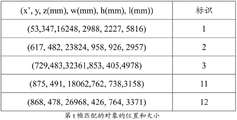
Fig. 8 (b) exemplarily shows particular location and the size (x (pixel) in the zone of these 5 objects that detect in the t frame, y (pixel), z (mm), w (mm), h (mm), l (mm)), wherein as previously mentioned, x, y represent horizontal ordinate and the ordinate of top left corner apex in the image of taking of this object, z represents the degree of depth of this object, the for example distance between binocular camera that this object and shooting are used, and w represents the width of this object, the height that h represents this object, l represents the degree of depth of this object itself.So, this x, y, z can represent the particular location of this object, and this w, h, l can represent the size of this object.
Note, in the present invention, can only with the particular location of object, be followed the tracks of, also can with particular location and the size both followed the tracks of, and be only for convenience of description in Fig. 8 (b) and understand, show particular location and both examples of size in the zone of these objects, but the invention is not restricted to this.
Fig. 8 (c) exemplarily shows the road end point in the t frame.
As before described, be applied to not necessarily road end point of predetermined reference point in method of the present invention, and can be the point with other physical meaning, for example as a reference point etc. with the sun.
As previously mentioned, the current unexposed patented claim that is entitled as " the road partage detection method based on parallax information " that to obtain application number that the method for road end point can submit on Dec 09th, 2011 to Patent Office of the People's Republic of China in same Applicant be 201110409269.1, and the Zhencheng Hu delivered on June 8th, 2005, Francisco Lamosa, being entitled as of Keiichi Uchimura " U-V-disparity:an efficient algorithm for stereovision based scene analysis " found in (ISBN:0-7695-2327-7), at this, these reference citations are invested to this.Certainly, those skilled in the art also can obtain by other or the following method that obtains the road end point that may occur horizontal ordinate or the ordinate of the road end point in the t frame.
Fig. 8 (d) exemplarily shows the subject area will detected in the t frame and is converted to the subject area based on this road end point.
As described above, in the situation that mainly consider that for example turn in the left and right of vehicle, the horizontal ordinate of the position of these predetermined reference point is by even more important, and can only use the horizontal ordinate of the position of these predetermined reference point, and in like manner, in the situation that mainly consider for example pitching of vehicle, the ordinate of the position of these predetermined reference point is by even more important, and can only use the ordinate of the position of these predetermined reference point, in like manner, in the situation that consider to turn and to pitch etc. such as the left and right of vehicle, both can use horizontal ordinate and the ordinate of the position of these predetermined reference point simultaneously.
Therefore, illustratively, at this, because the left and right turning phenomenon of vehicle is comparatively common and object offset distance that cause is larger, therefore in the disclosure, first only consider the horizontal ordinate of road end point.At this, the horizontal ordinate of the road end point that the patented claim that the application number that utilization is quoted is 201110409269.1 obtains is x
v=287 (pixel).(certainly, also can pass through the V-disparity map (along the V coordinate direction in image coordinate system (ordinate direction), scanning from top to bottom, the cumulative number with pixel of same disparity value, and the V-disparity map of setting up) obtain meaning the y coordinate of road end point, be the value of the y that on the V-disparity map, Road is 0 o'clock in parallax value, be the ordinate of road end point.At this, the disclosure is only set forth as an example with the horizontal ordinate that obtains the road end point, but the disclosure is not limited to this.)
Can find out that from Fig. 8 (d) the horizontal ordinate x of each subject area by the detection by obtaining in Fig. 8 (b) deducts the horizontal ordinate x of road end point
v=287 (pixel) obtain each subject area based on this road end point (x ', y, z, w, h, l)=(x-x
v, y, z, w, h, l).Particularly, for example, for object B, (340,347,16248,2988,2227,5816) are deducted to x
v=287 (pixel) obtain (53,347,16248,2988,2227,5816).
Certainly, in another embodiment, the invention is not restricted to only consider the horizontal ordinate of road end point, also can only consider the ordinate of road end point or horizontal ordinate and the ordinate of consideration road end point, those skilled in the art are also very clear in the situation that consider the ordinate of road end point or horizontal ordinate and the ordinate of consideration road end point, how to obtain each subject area based on this road end point, be not repeated herein.
Fig. 9 (a) and (b) be the schematic diagram that exemplarily is illustrated in two methods using when the tracking and matching of determining between each object detected in each object of detecting in the t-1 frame and t frame concerns.
At first with reference to figure 9 (a), according to the subject area based on the road end point of the t frame of the actual detection shown in Fig. 8 (d) (x ', y, z, w, h, l) (for example subject area 1), can obtain the cube of Fig. 9 (a) upper left, wherein the coordinate of top left corner apex be (x ', y, z), and the cubical wide of this object is w(mm), height is h(mm), and the degree of depth is l(mm).
According to the subject area based on the road end point of the t frame of estimating according to the t-1 frame shown in Fig. 7 (x '
p, y
p, z
p, w
p, h
p, l
p) (for example subject area B), can obtain the cube of Fig. 9 (a) bottom right, wherein the coordinate of top left corner apex be (x '
p, y
p, z
p), and the cubical wide of this object is w
p(mm), height is h
p(mm), and the degree of depth be l
p(mm).
If do not consider object size, do not consider (w, h, l) and (w
p, h
p, l
p) and only consider the position of object, only consider the object top left corner apex position (x ', y, z) and (x '
p, y
p, z
p) situation under, the method can comprise the object that calculates each t frame of estimating based on the t-1 frame position (x '
p, y
p, z
p) with each t frame in minor increment between the position (x ', y, z) of the actual object detected; If the minor increment of this calculating is less than predetermined threshold, determine with the t-1 frame in detect in this object of detecting and t frame should to as if mate.
That is to say, particularly, for example, by
 calculate the
 object 1 of the t frame of estimating based on the t-1 frame a position (x '
p, y
p, z
p) with each t frame between the position (x ', y, z) of actual each object B detected, C, E, A, D apart from d.Then, obtain these apart from the minor increment d in d
min(for example, suppose, the top left corner apex of object 1 and object B apart from the d minimum), and by the minor increment d in these distances
minwith predetermined threshold, compare, if this minor increment d
minbe less than predetermined threshold, this object 1 of determining the t-1 frame and this t frame there is minor increment d
minobject (for example for object B) be complementary.
Certainly the mode of calculating the distance between two objects is not limited to this, also can calculate by the distance between other points except top left corner apex, is not repeated herein.
That is to say, only consider the position of object, also can carry out the method for tracing object of disclosure enforcement.
Fig. 9 (b) show the position of not only considering the object top left corner apex (x ', y, z) and (x '
p, y
p, z
p), also consider size (w, h, l) and (w of object
p, h
p, l
p) situation under calculate the schematic diagram of the distance of two objects.
With reference to figure 9 (b), according to the subject area based on the road end point of the t frame of the actual detection shown in Fig. 8 (d) (x ', y, z, w, h, l) (for example subject area 1), can obtain the cube of Fig. 9 (b) upper left, wherein the coordinate of top left corner apex be (x ', y, z), and the cubical wide of this object is w(mm), height is h(mm), and the degree of depth is l(mm).The central point of the subject area of the t frame of this actual detection is c.
According to the subject area based on the road end point of the t frame of estimating according to the t-1 frame shown in Fig. 7 (x '
p, y
p, z
p, w
p, h
p, l
p) (for example subject area B), can obtain the cube of Fig. 9 (b) bottom right, wherein the coordinate of top left corner apex be (x '
p, y
p, z
p), and the cubical wide of this object is w
p(mm), height is h
p(mm), and the degree of depth be l
p(mm).The central point of the subject area of the t frame that this is estimated is c
p.
For example,, in order to calculate c and c
pbetween distance, pass through formula
Certainly the mode of calculating the distance between two objects is not limited to this, also can calculate by the distance between other points except Stereocenter point, is not repeated herein.
Determining all objects 1,2 of estimating ... 10 with detected object A, B ... after matching relationship between E, if estimate object and do not mate with any detected object for one, determine that estimate with this detected object that object is corresponding disappears in the t frame, if and detected object not with any object matching of estimating, determine that this detected object is new object in the t frame.
Like this, can determine more accurately the distance of two objects in solid space than the method shown in Fig. 9 (a), further to determine the tracking and matching relation.
Above, can obtain the tracking and matching relation between the object estimated in the t frame and the actual object detected with the calculating of simplifying, the tracking and matching relation in the actual detected object as the object with estimating in the t frame in corresponding t-1 frame and t frame between the object of reality detection.
Below, introduce the another kind of method that obtains more accurately the tracking and matching relation between the object of actual detection in actual detected object in the t-1 frame and t frame with complicated a little calculating.
Figure 10 (a)-(c) is the schematic diagram of the another kind of method when exemplarily being illustrated in the tracking and matching of determining between each object detected in each object of detecting in the t-1 frame and t frame and concerning.
The subject area based on the road end point of the t frame that obtains the actual detection as shown in Fig. 9 (b) (x ', y, z, w, h, l) (for example subject area 1), wherein the coordinate of top left corner apex be (x ', y, z), and the cubical wide of this object is w(mm), height is h(mm), and the degree of depth is l(mm), and the subject area based on the road end point of the t frame of estimating according to the t-1 frame (x '
p, y
p, z
p, w
p, h
p, l
p) (for example subject area B), wherein the coordinate of top left corner apex be (x '
p, y
p, z
p), and the cubical wide of this object is w
p(mm), height is h
p(mm), and the degree of depth be l
p(mm).
For example, for example, for the tracking and matching relation between the subject area based on the road end point (object B) of the subject area based on the road end point (object 1) of determining the actual t frame detected and the t frame estimated according to the t-1 frame, can pass through respectively following steps (can certainly be only through one of following steps, the order of these steps does not limit yet):
That based on each, estimates object estimates position (x ' for example
p, y
p, z
p) and size (w for example
p, h
p, l
p) and the relative position of described each detected object (x ' for example, y, z) and size (w for example, h, l), (for example, object 0,1,2 to estimate object for each ... 10), calculate each and estimate object and each detected object (for example object B, C, E, A, D) at the upper overlapping area of U-disparity map (that is, surface level).
Wherein, the U-disparity map means on surface level, and the appearance of each object of looking from top to bottom, as shown in Figure 10 (a), looks as seen from top to bottom, on surface level, only considers wide w and the w of object
pand the degree of depth l of object and l
p, and can't see, also not consider height h and the h of object
p.
Then, for example, for example, for example, if one is estimated one of object (object 1) and detected object (object B, C, E, A, D) (object B) overlapping area maximum on the U-disparity map, determine that estimating one of for example, detected object (for example remaining object 1) in the t-1 frame that object (object 1) is corresponding and the detected object in the t frame (for example object B) with this mates.
Particularly, with reference to Figure 10 (a), calculated example as object 1 and object B for example on the U-disparity map during overlapping area (area of dash area in as Figure 10 (a)), can pass through formula S u=(x '+w – x '
p) * (z
p+ l
p-z) calculate.Having calculated respectively object 1 and object B, object 1 and object C, object 1 and object E, object 1 and object A, object 1 is all with object D's) on the U-disparity map after overlapping area, the object (for example object B) of determining area maximum overlapping on the U-disparity map is as the object be complementary with object 1.
So, only utilize the calculating of the overlapping area on the U-disparity map can determine whether to have mated these objects.This U-disparity map is due to the appearance of the object of only considering to look from the top down, therefore can suitably eliminate being offset up and down of binocular camera and the error that causes.And, in the situation that the error that before combining, the conversion based on the road end point has caused to have eliminated the skew of binocular camera left and right, this embodiment can eliminate the skew up and down of binocular camera and the impact that the left and right skew causes simultaneously.
But, sometimes, overlapping area on the U-disparity map so not necessarily only has a maximal value, if one to estimate object and two above detected objects overlapping area on described U-disparity map all maximum, can calculate this and estimate object and go up overlapping area with two above detected objects at X-Y-disparity map (being depth plane).Wherein the X-Y-disparity map means on depth plane, and the appearance of each object of looking from front to back, as shown in Figure 10 (b), as seen from looking from front to back, on depth plane, is only considered wide w and the w of object
pand height h and the h of object
p, and can't see, also not consider degree of depth l and the l of object
p.
If this estimates one of object and described two above detected objects overlapping area maximum on the X-Y-disparity map, determine that estimating one of detected object in the t-1 frame that object is corresponding and described two the above detected objects in the t frame with this mates.
Particularly, with reference to Figure 10 (b), estimate object and detected object in calculating and during overlapping area (area of dash area in as Figure 10 (b)), can pass through formula S on the X-Y-disparity map
x-y=(x '+w – x '
p) * (y
p+ h
p-y) calculate.Estimate object and this two above detected objects on the X-Y-disparity map after overlapping area having calculated respectively, a detected object determining area maximum overlapping on the X-Y-disparity map is as the object with estimating object and being complementary, and can determine to estimate detected object in the t-1 frame that object is corresponding with this and this detected object in the t frame mates.
For example, after the calculating of the overlapping area on having passed through U-disparity map and X-Y disparity map, concrete numerical value by disclosed each subject area in the disclosure, can obtain object B and 1, the overlapping area of object C and 2 in U-disparity map and/or X-Y-disparity map all is greater than 0, other overlapping areas are all 0, therefore can obtain object 1 and object B coupling, object 2 and object C coupling.
Certainly, the disclosure should be mentioned that the overlapping area of first calculating the U-disparity map, the overlapping area of just using the X-Y-disparity map when overlapping area has 2 maximum areas, but the disclosure is not limited to this, also can carry out separately the tracking and matching of object by the overlapping area of X-Y-disparity map, even can also use alone or in combination V-disparity map (appearance of the object of looking from left to right) to carry out tracking and matching of object etc.
If, after the calculating of the U-disparity map by Figure 10 (a) and Figure 10 (b) and the overlapping area of X-Y-disparity map, some of t frame (are for example estimated object, object 3,4 ... 10) and some detected objects of t frame (for example, object A, E, D) still do not mated, can calculate not the minor increment between the described position of estimating position and each detected object do not mated of estimating object of each of coupling; For example, if the minor increment of this calculating is less than predetermined threshold (before predetermined 6 meters), determine that the detected object of estimating detected object of the t-1 frame that object is corresponding with this and having a t frame of minor increment mates.
By the concrete numerical value of disclosed each subject area in the disclosure, can calculate object 3 and the distance that has between the object E of minor increment is 2 meters, be less than 6 meters of predetermined thresholds, so object 3 and object E coupling.
The method of the distance between two objects of concrete calculating can be as before with reference to the method as shown in figure 9 (a) and 9 (b), be not repeated herein.Certainly, the disclosure also is not limited to this.
The exemplary mode that shows the distance between the Stereocenter point that calculates two objects only in Figure 10 (c), this is only more accurate in order to make determining of tracking and matching relation, rather than limits.
Finally, if estimate object and do not mate with any detected object for one, determine that estimate with this detected object that object is corresponding disappears in the t frame, and if detected object not with any object matching of estimating, definite this detected object is new object in the t frame.
Particularly, in this example, object 4,5 ... 10 all do not have coupling, and these objects 4,5 are described ... 10 have disappeared in the t frame.And in the object detected in the t frame, have 2 detected objects and all objects of estimating not to mate, and illustrate two new objects to have occurred in the t frame, can respectively it be designated to object 11 and object 12.
Figure 11 (a)-(b) is the schematic diagram in zone that exemplarily is illustrated in the object of the coupling of determining that the tracking and matching relation between each object detected in each object of detecting in the t-1 frame and t frame obtains afterwards.
Figure 11 (a) shows through above-mentioned and calculates, the object 0,1,2 detected in the object B detected in the t frame, C, E, A, D and t-1 frame ... tracking and matching relation between 10.Visible, object B and object 1 coupling, object C and object 2 couplings, object E and object 3 couplings, object 11 and 12 is emerging two objects in the t frame, therefore by new sign 11,12, means respectively.
Figure 11 (b) shows the square frame of the subject area of coupling finally definite in the image of t frame visually.
Like this, by using separately or in combination overlapping area and the distance on U-disparity map, X-Y-disparity map, can determine more accurately the tracking and matching relation of two objects than the method for the only service range shown in Fig. 9 (a) and Fig. 9 (b).
So, according to these one or more embodiment, can obtain more accurately the tracking and matching relation between the object estimated in the t frame and the actual object detected, the tracking and matching relation in the actual detected object as the object with estimating in the t frame in corresponding t-1 frame and t frame between the object of actual detection.
Figure 12 exemplarily illustrates pre-motion orientation and the predetermined movement velocity (or displacement) of proofreading and correct each object detected in the t-1 frame, as pre-motion orientation and the predetermined movement velocity (or displacement) of each object detected in the t frame with its coupling.
In determining the t-1 frame in each detected object and t frame after the tracking and matching relation between each detected object, the position based on the road end point based on each detected object in the t-1 frame and with the t frame of its coupling in the position based on the road end point of each detected object, can proofread and correct pre-motion orientation and the predetermined movement velocity of each detected object in the t-1 frame, as pre-motion orientation and the predetermined movement velocity of each detected object in the t frame with its coupling.
Certainly, in the disclosure, in order to simplify calculating, in the situation that the time interval between each frame of hypothesis is equal, only by displacement, mean the concept of direction of motion and movement velocity.
Δx=x’
t–x’
t-1,Δy=y
t–y
t-1,Δz=z
t–z
t-1。To new object 11 and 12, (Δ x, Δ y, Δ z)=(0,0,0).X ' wherein
tthe horizontal ordinate that means the position based on the road end point of the detected object in the t frame, and x '
t-1the horizontal ordinate that means the position based on the road end point of the detected object in the t-1 frame, y
tthe ordinate that means the position based on the road end point of the detected object in the t frame, and y
t-1the ordinate that means the position based on the road end point of the detected object in the t-1 frame, z
tthe depth coordinate that means the position based on the road end point of the detected object in the t-1 frame, and z
t-1the depth coordinate that means the position based on the road end point of the detected object in the t frame.
If calculated (Δ x, Δ y, Δ z), can, by the time interval between t-1 frame and t frame, infer direction of motion and the movement velocity of each detected object in the t frame.Wherein, this Δ x, Δ y, the arbitrary value in Δ z, for example Δ x get on the occasion of, the positive dirction that the direction of motion corresponding to object on the x axle is the x axle, and for example Δ x gets the negative value negative direction that the direction of motion on the x axle is the x axle corresponding to object.
As shown in Figure 12, for example, after correction, the displacement that is designated 1 object in the t frame is (3 ,-18 ,-1730), and in the t frame, the displacement of emerging new object 11 is (0,0,0).It should be noted that in the disclosure, (get on the occasion of or negative value) displacement can be used convertibly with movement velocity and direction of motion.
Below will exemplarily introduce the displacement of each object that utilizes the t frame after proofreading and correct each object detected in the t+1 frame will be carried out to tracking and matching.Certainly, those skilled in the art are according to the detailed description of the method for the tracking and matching of the object to t-1 frame and t frame in the disclosure, can infer for each object detected in the t+1 frame and carry out the mode of tracking and matching, but, in order to make the disclosure clearer, below still this is described, but these descriptions are not restrictive.
Figure 13 (a)-(e) exemplarily illustrates the displacement of utilizing after proofreading and correct the t+1 frame to be determined to the schematic diagram of tracking and matching relation.
The subject area based on the road end point of the displacement of the object (for example object 1,2,3,11,12) of the t frame after Figure 13 (a) exemplarily shows and utilize to proofread and correct and the object of t frame (x ', y, z, w, h, l), estimate the subject area based on the road end point of estimating object in the t+1 frame (x '
p, y
p, z
p, w
p, h
p, l
p).Wherein, x
p=x '+Δ x, y
p=yt+ Δ y, z
p=z
t+ Δ z, w
p=w, h
p=h, l
p=l, i.e. (x
p, y
p, z
p, w
p, h
p, l
p)=(x '+Δ x, y+ Δ y, z+ Δ z, w, h, l).
Then, utilize the current unexposed patented claim that is entitled as " road method for checking object and system " that above-mentioned application number is 201110369183.0 (or in other prior aries the disclosed or following method for checking object that may occur) to detect the subject area (position and size) of the object (for example object A, B, C, D, E, F, G, H) of the actual detection in the t+1 frame, see shown in Figure 13 (b) and Figure 13 (c).
Then, utilize the current unexposed patented claim that is entitled as " the road partage detection method based on parallax information " that above-mentioned application number is 201110409269.1 (or in other prior aries the disclosed or following road vanishing Point Detection Method method that may occur) to detect the horizontal ordinate x that obtains the road end point
v=122 (pixel).
Similarly, the horizontal ordinate x of the subject area of each object (for example object A, B, C, D, E, F, G, H) of the detection by the t+1 frame deducts the horizontal ordinate x of road end point
v=122 (pixel) obtain each subject area (x ', y, z, w, h, l) of this road end point based on the t+1 frame=(x-x
v, y, z, w, h, l), as shown in Figure 13 (d).
Then, determine the tracking and matching relation between object 1,2,3,11,12 and object A, B, C, D, E, F, G, H by reference to the method shown in Fig. 9 (a) or Fig. 9 (b) or with reference to the method shown in Figure 10 (a)-10 (c).Be not repeated herein.
Thereby obtain the subject area of the coupling as shown in Figure 13 (e).
Therefore, can further proofread and correct the displacement of object of each coupling of t+1 frame with the tracking and matching for next frame (t+2 frame).So move in circles, can the Continuous Tracking object, with for traffic monitoring, the auxiliary driving, automobile detection and tracking, each practical field such as alarm drive system, robot visual guidance, industrial products detection, medical diagnosis, virtual reality.
Mainly set forth each step of method of tracing object and the step of some variation of having given an example in the disclosure, those skilled in the art can know, with the step of these steps and variation, install one to one also and should, in the scope of the present disclosure, be not repeated herein.
Here all patents of quoting, patented claim, article, other publications, document and things are quoted and are merged it in full by this at this for all purposes.Any inconsistent of term definition or use arranged or conflict if any between publication, document or the things of any merging and the disclosure, being as the criterion with the disclosure.
Certainly, those skilled in the art have been appreciated that the essential implication of each term according to the disclosure, content of the present disclosure also not only is confined to the given narrow implication of concrete term, but can indicate the implication widely in spirit of the present disclosure and principle.
More than open the description based on disparity map carried out each embodiment of the method and system of tracing object exactly, and still, foregoing description is exemplary, exhaustive not, and also be not limited to each disclosed embodiment.In the situation that do not depart from the scope and spirit of each illustrated embodiment, many modifications and changes are all apparent for those skilled in the art.It should be appreciated by those skilled in the art that in the scope of claims or its equivalent, can need to carry out various modifications, combination, sub-portfolio and change with other factors based on design.
Claims (10)
1. the method for tracing object in disparity map comprises the following steps:
The first detecting step, detect one or more the first detected objects in the first disparity map and obtain the position of each the first detected object;
The first switch process, each of coordinate that the position of each the first detected object is converted to the first predetermined reference point based in the first disparity map first detects relative position;
Estimate step, based on each the first pre-motion orientation and predetermined movement velocity that detects relative position and each the first detected object, estimate in the second disparity map each first position of estimating of estimating object corresponding to each the first detected object;
The second detecting step, detect one or more the second detected objects in the second disparity map and obtain the position of each the second detected object;
The second switch process, each of coordinate that the position of each the second detected object is converted to the second predetermined reference point based in the second disparity map second detects relative position;
Determining step, detect relative position based on each first second of position and described each second detected object of estimating of estimating object, determine with each and first estimate each first detected object that object is corresponding and the tracking and matching relation between each the second detected object.
2. method according to claim 1, wherein, the coordinate of described the first predetermined reference point is included in the horizontal ordinate of end point of the road in the first disparity map and at least one in ordinate, and the coordinate of described the second predetermined reference point is included in the horizontal ordinate of end point of the same road in the second disparity map and at least one in ordinate.
3. method according to claim 1, wherein, described the first detecting step also obtains the size of each the first detected object, wherein, the size of each the first detected object is as each the first size of estimating object, and described the second detecting step also obtains the size of each the second detected object
Wherein, described determining step detects relative position and size based on each first second of position and size and each second detected object of estimating of estimating object, and determines the tracking and matching relation between each first detected object and each the second detected object.
4. method according to claim 3, wherein, described determining step comprises the following steps:
Detect relative position and size based on each first second of position and size and described each second detected object of estimating of estimating object, first estimate object for each, calculate each and first estimate object and each the second detected object overlapping area on surface level;
If one first is estimated one of object and second detected object overlapping area maximum on described surface level, determine with this and first estimate one of the first detected object that object is corresponding and described second detected object and mate.
5. method according to claim 4, wherein, described determining step is further comprising the steps of:
If one first estimate object and more than two the second detected object overlapping area on described surface level all maximum, calculate this and first estimate object and the second detected object overlapping area on depth plane more than two;
If this first estimates object and described one of second detected object overlapping area maximum on depth plane more than two, determine with this first estimate the first detected object that object is corresponding and described more than two one of second detected object mate.
6. method according to claim 1 or 5, wherein, described determining step is further comprising the steps of:
Calculate each described first minor increment of estimating between the second detection relative position of estimating position and each the second detected object of coupling not of object of coupling not;
If the minor increment of this calculating is less than predetermined threshold, determines with this first the second detected object of estimating the first detected object that object is corresponding and thering is minor increment and mate.
7. method according to claim 6, wherein, described predetermined threshold is based on to be determined with the described first maximum movement speed of estimating the first detected object that object is corresponding.
8. method according to claim 6, wherein, described determining step is further comprising the steps of:
If first detected object does not mate with any the second detected object, determine that this first detected object disappears in the second disparity map, and
If second detected object does not mate with any the first detected object, determine that this second detected object is new object in the second disparity map.
9. method according to claim 1 also comprises:
After the tracking and matching relation of determining between each first detected object and each the second detected object, first-phase based on each the first detected object to detection position and with the second-phase of each the second detected object of its coupling to detection position, proofread and correct pre-motion orientation and the predetermined movement velocity of each the first detected object, as pre-motion orientation and the predetermined movement velocity of each the second detected object with its coupling.
10. the object-tracking systems in disparity map comprises:
The first pick-up unit, detect one or more the first detected objects in the first disparity map and obtain the position of each the first detected object;
The first conversion equipment, each of coordinate that the position of each the first detected object is converted to the first predetermined reference point based in the first disparity map first detects relative position;
Estimating device, based on each the first pre-motion orientation and predetermined movement velocity that detects relative position and each the first detected object, estimate in the second disparity map each first position of estimating of estimating object corresponding to each the first detected object;
Second detection device, detect one or more the second detected objects in the second disparity map and obtain the position of each the second detected object;
The second conversion equipment, each of coordinate that the position of each the second detected object is converted to the second predetermined reference point based in the second disparity map second detects relative position;
Determine device, detect relative position based on each first second of position and described each second detected object of estimating of estimating object, determine with each and first estimate each first detected object that object is corresponding and the tracking and matching relation between each the second detected object.
Priority Applications (2)
| Application Number | Priority Date | Filing Date | Title |
|---|---|---|---|
| CN201210188661.2A CN103473757B (en) | 2012-06-08 | 2012-06-08 | Method for tracing object in disparity map and system |
| JP2013120605A JP6171593B2 (en) | 2012-06-08 | 2013-06-07 | Object tracking method and system from parallax map |
Applications Claiming Priority (1)
| Application Number | Priority Date | Filing Date | Title |
|---|---|---|---|
| CN201210188661.2A CN103473757B (en) | 2012-06-08 | 2012-06-08 | Method for tracing object in disparity map and system |
Publications (2)
| Publication Number | Publication Date |
|---|---|
| CN103473757A true CN103473757A (en) | 2013-12-25 |
| CN103473757B CN103473757B (en) | 2016-05-25 |
Family
ID=49798591
Family Applications (1)
| Application Number | Title | Priority Date | Filing Date |
|---|---|---|---|
| CN201210188661.2A Active CN103473757B (en) | 2012-06-08 | 2012-06-08 | Method for tracing object in disparity map and system |
Country Status (2)
| Country | Link |
|---|---|
| JP (1) | JP6171593B2 (en) |
| CN (1) | CN103473757B (en) |
Cited By (9)
| Publication number | Priority date | Publication date | Assignee | Title |
|---|---|---|---|---|
| CN104915964A (en) * | 2014-03-11 | 2015-09-16 | 株式会社理光 | Object tracking method and device |
| CN104978558A (en) * | 2014-04-11 | 2015-10-14 | 北京数码视讯科技股份有限公司 | Target identification method and device |
| CN105335955A (en) * | 2014-07-17 | 2016-02-17 | 株式会社理光 | Object detection method and object detection apparatus |
| CN107223219A (en) * | 2016-09-26 | 2017-09-29 | 深圳市大疆创新科技有限公司 | Control method, control device and delivery system |
| CN107403440A (en) * | 2016-05-18 | 2017-11-28 | 株式会社理光 | For the method and apparatus for the posture for determining object |
| CN107909012A (en) * | 2017-10-30 | 2018-04-13 | 北京中科慧眼科技有限公司 | A kind of real-time vehicle tracking detection method and device based on disparity map |
| CN109903308A (en) * | 2017-12-08 | 2019-06-18 | 百度在线网络技术(北京)有限公司 | For obtaining the method and device of information |
| CN110059591A (en) * | 2019-04-01 | 2019-07-26 | 北京中科晶上超媒体信息技术有限公司 | The recognition methods of motion target area |
| WO2021078283A1 (en) * | 2019-10-24 | 2021-04-29 | 华为技术有限公司 | Data association method and device |
Families Citing this family (3)
| Publication number | Priority date | Publication date | Assignee | Title |
|---|---|---|---|---|
| CN105898265A (en) * | 2014-12-18 | 2016-08-24 | 陆婷 | Novel stereo video-based human body tracking method |
| JP2018051728A (en) * | 2016-09-30 | 2018-04-05 | ファナック株式会社 | Detection method and detection apparatus for detecting three-dimensional position of object |
| CA3168579C (en) * | 2018-04-09 | 2026-03-31 | Dolby International Ab | Methods, apparatus and systems for three degrees of freedom (3dof+) extension of mpeg-h 3d audio |
Citations (7)
| Publication number | Priority date | Publication date | Assignee | Title |
|---|---|---|---|---|
| CN101029823A (en) * | 2006-02-28 | 2007-09-05 | 沈阳东软软件股份有限公司 | Method for tracking vehicle based on state and classification |
| CN101098465A (en) * | 2007-07-20 | 2008-01-02 | 哈尔滨工程大学 | A method for detecting and tracking moving objects in video surveillance |
| WO2010042068A1 (en) * | 2008-10-06 | 2010-04-15 | Agency For Science, Technology And Research | Method and system for object detection and tracking |
| CN101706576A (en) * | 2009-11-13 | 2010-05-12 | 山东大学 | Radar image based moving target morphology detecting and tracking method |
| CN101727570A (en) * | 2008-10-23 | 2010-06-09 | 华为技术有限公司 | Tracking method, track detection processing unit and monitor system |
| CN101739551A (en) * | 2009-02-11 | 2010-06-16 | 北京智安邦科技有限公司 | Method and system for identifying moving objects |
| CN102214359A (en) * | 2010-04-07 | 2011-10-12 | 北京智安邦科技有限公司 | Target tracking device and method based on hierarchic type feature matching |
Family Cites Families (3)
| Publication number | Priority date | Publication date | Assignee | Title |
|---|---|---|---|---|
| JP2940366B2 (en) * | 1993-12-07 | 1999-08-25 | 住友電気工業株式会社 | Object tracking recognition device |
| JP4856612B2 (en) * | 2007-10-29 | 2012-01-18 | 富士重工業株式会社 | Object detection device |
| JP2011185664A (en) * | 2010-03-05 | 2011-09-22 | Panasonic Electric Works Co Ltd | Object detector |
-
2012
- 2012-06-08 CN CN201210188661.2A patent/CN103473757B/en active Active
-
2013
- 2013-06-07 JP JP2013120605A patent/JP6171593B2/en not_active Expired - Fee Related
Patent Citations (7)
| Publication number | Priority date | Publication date | Assignee | Title |
|---|---|---|---|---|
| CN101029823A (en) * | 2006-02-28 | 2007-09-05 | 沈阳东软软件股份有限公司 | Method for tracking vehicle based on state and classification |
| CN101098465A (en) * | 2007-07-20 | 2008-01-02 | 哈尔滨工程大学 | A method for detecting and tracking moving objects in video surveillance |
| WO2010042068A1 (en) * | 2008-10-06 | 2010-04-15 | Agency For Science, Technology And Research | Method and system for object detection and tracking |
| CN101727570A (en) * | 2008-10-23 | 2010-06-09 | 华为技术有限公司 | Tracking method, track detection processing unit and monitor system |
| CN101739551A (en) * | 2009-02-11 | 2010-06-16 | 北京智安邦科技有限公司 | Method and system for identifying moving objects |
| CN101706576A (en) * | 2009-11-13 | 2010-05-12 | 山东大学 | Radar image based moving target morphology detecting and tracking method |
| CN102214359A (en) * | 2010-04-07 | 2011-10-12 | 北京智安邦科技有限公司 | Target tracking device and method based on hierarchic type feature matching |
Non-Patent Citations (2)
| Title |
|---|
| 田恒燕: "《基于双目立体视觉的目标跟踪方法研究》", 《中国优秀硕士学位论文全文数据库信息科技辑》 * |
| 高欣等: "《基于视差和变化检测的立体视频对象分割》", 《上海大学学报(自然科学版)》 * |
Cited By (17)
| Publication number | Priority date | Publication date | Assignee | Title |
|---|---|---|---|---|
| CN104915964B (en) * | 2014-03-11 | 2017-08-11 | 株式会社理光 | Method for tracing object and equipment |
| CN104915964A (en) * | 2014-03-11 | 2015-09-16 | 株式会社理光 | Object tracking method and device |
| CN104978558A (en) * | 2014-04-11 | 2015-10-14 | 北京数码视讯科技股份有限公司 | Target identification method and device |
| CN104978558B (en) * | 2014-04-11 | 2018-05-08 | 北京数码视讯科技股份有限公司 | The recognition methods of target and device |
| CN105335955B (en) * | 2014-07-17 | 2018-04-10 | 株式会社理光 | Method for checking object and object test equipment |
| CN105335955A (en) * | 2014-07-17 | 2016-02-17 | 株式会社理光 | Object detection method and object detection apparatus |
| US9576367B2 (en) | 2014-07-17 | 2017-02-21 | Ricoh Company, Ltd. | Object detection method and device |
| CN107403440B (en) * | 2016-05-18 | 2020-09-08 | 株式会社理光 | Method and apparatus for determining a pose of an object |
| CN107403440A (en) * | 2016-05-18 | 2017-11-28 | 株式会社理光 | For the method and apparatus for the posture for determining object |
| CN107223219A (en) * | 2016-09-26 | 2017-09-29 | 深圳市大疆创新科技有限公司 | Control method, control device and delivery system |
| US11092975B2 (en) | 2016-09-26 | 2021-08-17 | SZ DJI Technology Co., Ltd. | Control method, control device, and carrier system |
| US11724805B2 (en) | 2016-09-26 | 2023-08-15 | SZ DJI Technology Co., Ltd. | Control method, control device, and carrier system |
| CN107909012A (en) * | 2017-10-30 | 2018-04-13 | 北京中科慧眼科技有限公司 | A kind of real-time vehicle tracking detection method and device based on disparity map |
| CN107909012B (en) * | 2017-10-30 | 2022-03-18 | 北京中科慧眼科技有限公司 | Real-time vehicle tracking detection method and device based on disparity map |
| CN109903308A (en) * | 2017-12-08 | 2019-06-18 | 百度在线网络技术(北京)有限公司 | For obtaining the method and device of information |
| CN110059591A (en) * | 2019-04-01 | 2019-07-26 | 北京中科晶上超媒体信息技术有限公司 | The recognition methods of motion target area |
| WO2021078283A1 (en) * | 2019-10-24 | 2021-04-29 | 华为技术有限公司 | Data association method and device |
Also Published As
| Publication number | Publication date |
|---|---|
| CN103473757B (en) | 2016-05-25 |
| JP2013257872A (en) | 2013-12-26 |
| JP6171593B2 (en) | 2017-08-02 |
Similar Documents
| Publication | Publication Date | Title |
|---|---|---|
| CN103473757A (en) | Object tracking method in disparity map and system thereof | |
| EP1394761B1 (en) | Obstacle detection device and method therefor | |
| US8233660B2 (en) | System and method for object motion detection based on multiple 3D warping and vehicle equipped with such system | |
| US10354151B2 (en) | Method of detecting obstacle around vehicle | |
| US10466714B2 (en) | Depth map estimation with stereo images | |
| US8154594B2 (en) | Mobile peripheral monitor | |
| US8564657B2 (en) | Object motion detection system based on combining 3D warping techniques and a proper object motion detection | |
| US8331653B2 (en) | Object detector | |
| EP3057063B1 (en) | Object detection device and vehicle using same | |
| KR100909741B1 (en) | Monitoring device, monitoring method | |
| US20080253606A1 (en) | Plane Detector and Detecting Method | |
| CN101408978B (en) | Method and apparatus for detecting barrier based on monocular vision | |
| US20090041337A1 (en) | Image processing apparatus and method | |
| EP2256690B1 (en) | Object motion detection system based on combining 3D warping techniques and a proper object motion detection | |
| WO2019181284A1 (en) | Information processing device, movement device, method, and program | |
| JP5982298B2 (en) | Obstacle detection device and obstacle detection method | |
| JP2023089311A (en) | Information processing device, image capturing system, information processing method, and computer program | |
| JP2010072807A (en) | Device for detecting and determining road boundary | |
| CN105480227B (en) | A method based on fusion of infrared radar and video image information in active driving technology | |
| CN101727756A (en) | Mobile image aided guidance method and system for vehicle | |
| JP6552448B2 (en) | Vehicle position detection device, vehicle position detection method, and computer program for vehicle position detection | |
| Musleh et al. | Visual ego motion estimation in urban environments based on uv disparity | |
| Lim et al. | Distance estimation algorithm for both long and short ranges based on stereo vision system | |
| CN112519773B (en) | Lane keeping method and device for intelligently driving automobile and automobile | |
| WO2015122212A1 (en) | Vehicle-mounted recognition device |
Legal Events
| Date | Code | Title | Description |
|---|---|---|---|
| C06 | Publication | ||
| PB01 | Publication | ||
| C10 | Entry into substantive examination | ||
| SE01 | Entry into force of request for substantive examination | ||
| C14 | Grant of patent or utility model | ||
| GR01 | Patent grant |