CN103703295A - Single-lever mixing cartridge - Google Patents
Single-lever mixing cartridge Download PDFInfo
- Publication number
- CN103703295A CN103703295A CN201380001401.2A CN201380001401A CN103703295A CN 103703295 A CN103703295 A CN 103703295A CN 201380001401 A CN201380001401 A CN 201380001401A CN 103703295 A CN103703295 A CN 103703295A
- Authority
- CN
- China
- Prior art keywords
- monolever
- mixing drum
- base member
- mixing
- disk
- Prior art date
- Legal status (The legal status is an assumption and is not a legal conclusion. Google has not performed a legal analysis and makes no representation as to the accuracy of the status listed.)
- Granted
Links
Images


Classifications
-
- F—MECHANICAL ENGINEERING; LIGHTING; HEATING; WEAPONS; BLASTING
- F16—ENGINEERING ELEMENTS AND UNITS; GENERAL MEASURES FOR PRODUCING AND MAINTAINING EFFECTIVE FUNCTIONING OF MACHINES OR INSTALLATIONS; THERMAL INSULATION IN GENERAL
- F16K—VALVES; TAPS; COCKS; ACTUATING-FLOATS; DEVICES FOR VENTING OR AERATING
- F16K27/00—Construction of housing; Use of materials therefor
- F16K27/04—Construction of housing; Use of materials therefor of sliding valves
-
- F—MECHANICAL ENGINEERING; LIGHTING; HEATING; WEAPONS; BLASTING
- F16—ENGINEERING ELEMENTS AND UNITS; GENERAL MEASURES FOR PRODUCING AND MAINTAINING EFFECTIVE FUNCTIONING OF MACHINES OR INSTALLATIONS; THERMAL INSULATION IN GENERAL
- F16K—VALVES; TAPS; COCKS; ACTUATING-FLOATS; DEVICES FOR VENTING OR AERATING
- F16K27/00—Construction of housing; Use of materials therefor
-
- F—MECHANICAL ENGINEERING; LIGHTING; HEATING; WEAPONS; BLASTING
- F16—ENGINEERING ELEMENTS AND UNITS; GENERAL MEASURES FOR PRODUCING AND MAINTAINING EFFECTIVE FUNCTIONING OF MACHINES OR INSTALLATIONS; THERMAL INSULATION IN GENERAL
- F16K—VALVES; TAPS; COCKS; ACTUATING-FLOATS; DEVICES FOR VENTING OR AERATING
- F16K11/00—Multiple-way valves, e.g. mixing valves; Pipe fittings incorporating such valves
- F16K11/02—Multiple-way valves, e.g. mixing valves; Pipe fittings incorporating such valves with all movable sealing faces moving as one unit
- F16K11/06—Multiple-way valves, e.g. mixing valves; Pipe fittings incorporating such valves with all movable sealing faces moving as one unit comprising only sliding valves, i.e. sliding closure elements
- F16K11/078—Multiple-way valves, e.g. mixing valves; Pipe fittings incorporating such valves with all movable sealing faces moving as one unit comprising only sliding valves, i.e. sliding closure elements with pivoted and linearly movable closure members
- F16K11/0782—Single-lever operated mixing valves with closure members having flat sealing faces
- F16K11/0787—Single-lever operated mixing valves with closure members having flat sealing faces with both the supply and the discharge passages being on the same side of the closure members
-
- F—MECHANICAL ENGINEERING; LIGHTING; HEATING; WEAPONS; BLASTING
- F16—ENGINEERING ELEMENTS AND UNITS; GENERAL MEASURES FOR PRODUCING AND MAINTAINING EFFECTIVE FUNCTIONING OF MACHINES OR INSTALLATIONS; THERMAL INSULATION IN GENERAL
- F16K—VALVES; TAPS; COCKS; ACTUATING-FLOATS; DEVICES FOR VENTING OR AERATING
- F16K11/00—Multiple-way valves, e.g. mixing valves; Pipe fittings incorporating such valves
- F16K11/02—Multiple-way valves, e.g. mixing valves; Pipe fittings incorporating such valves with all movable sealing faces moving as one unit
- F16K11/06—Multiple-way valves, e.g. mixing valves; Pipe fittings incorporating such valves with all movable sealing faces moving as one unit comprising only sliding valves, i.e. sliding closure elements
- F16K11/078—Multiple-way valves, e.g. mixing valves; Pipe fittings incorporating such valves with all movable sealing faces moving as one unit comprising only sliding valves, i.e. sliding closure elements with pivoted and linearly movable closure members
-
- F—MECHANICAL ENGINEERING; LIGHTING; HEATING; WEAPONS; BLASTING
- F16—ENGINEERING ELEMENTS AND UNITS; GENERAL MEASURES FOR PRODUCING AND MAINTAINING EFFECTIVE FUNCTIONING OF MACHINES OR INSTALLATIONS; THERMAL INSULATION IN GENERAL
- F16K—VALVES; TAPS; COCKS; ACTUATING-FLOATS; DEVICES FOR VENTING OR AERATING
- F16K27/00—Construction of housing; Use of materials therefor
- F16K27/04—Construction of housing; Use of materials therefor of sliding valves
- F16K27/044—Construction of housing; Use of materials therefor of sliding valves slide valves with flat obturating members
-
- Y—GENERAL TAGGING OF NEW TECHNOLOGICAL DEVELOPMENTS; GENERAL TAGGING OF CROSS-SECTIONAL TECHNOLOGIES SPANNING OVER SEVERAL SECTIONS OF THE IPC; TECHNICAL SUBJECTS COVERED BY FORMER USPC CROSS-REFERENCE ART COLLECTIONS [XRACs] AND DIGESTS
- Y10—TECHNICAL SUBJECTS COVERED BY FORMER USPC
- Y10T—TECHNICAL SUBJECTS COVERED BY FORMER US CLASSIFICATION
- Y10T137/00—Fluid handling
- Y10T137/6851—With casing, support, protector or static constructional installations
Landscapes
- Engineering & Computer Science (AREA)
- General Engineering & Computer Science (AREA)
- Mechanical Engineering (AREA)
- Multiple-Way Valves (AREA)
- Domestic Plumbing Installations (AREA)
- Mixers With Rotating Receptacles And Mixers With Vibration Mechanisms (AREA)
- Accessories For Mixers (AREA)
- Mixers Of The Rotary Stirring Type (AREA)
Abstract
Description
技术领域 technical field
本发明涉及一种单手柄混合筒(Einhandhebelmischerkartusche),其包括:头部件(Kopfstueck),其容纳底部件;以及带有控制盘的盘控制部(Scheibensteuerung),其经由至少可摆动地支承的心轴可移动地来布置。 The invention relates to a single-handle mixing drum (Einhandhebelmischerkartusche), which comprises: a head part (Kopfstueck), which accommodates a bottom part; The shaft is arranged movably.
背景技术 Background technique
在卫生器具中经常使用混合筒,在其中布置有具有控制盘以及通过盘(Durchlassscheibe)的盘控制部,其经由唯一的杆可操纵成使得不仅水量而且水温度可经由同一杆控制。这样的可更换的筒可应用在不同地设计的器具壳体中。在一些应用领域中也可应用修改的筒,在其中建立恒定的混合比,其中,锁止杆的旋转运动,使得仅经由杆的摆动运动可实现水量的调节。该实施方案也应用在这样的应用领域中,在其中在器具中仅存在输入通道。 Mixing cartridges are frequently used in sanitary ware, in which a disc control with a control disc and a through disc is arranged, which can be actuated via a single lever in such a way that both the water quantity and the water temperature can be controlled via the same lever. Such an exchangeable cartridge can be used in differently designed appliance housings. Modified cartridges are also available in some fields of application, in which a constant mixing ratio is established, wherein the rotational movement of the lever is locked so that adjustment of the water quantity is possible only via a pivoting movement of the lever. This embodiment is also used in fields of application in which only supply channels are present in the appliance.
在器具壳体的设计中越来越多地存在对尽可能小的结构的期望。由此需要小而紧凑地构建混合筒,其中,同时存在对较大水量的要求。混合筒通常由注塑件组装而成,其中,由于构件的较小的尺寸,与用于水通过的大尺寸的通过口相联系局部地存在仅较小的材料强度。 In the design of appliance housings there is an increasing desire to have the smallest possible structure. This requires a small and compact construction of the mixing cartridge, wherein at the same time a large water quantity is required. Mixing cartridges are usually assembled from injection-molded parts, wherein, due to the small dimensions of the components, locally there is only a low material strength in connection with the large passage openings for the passage of water.
在器具的设计中,除了尺寸之外还经常要求侧向的出水口。这样的侧向的出水口被实现成使得混合筒的底部被设有小脚,使得流出的水可在筒的底部件与器具的容纳部的底部之间流出并且被引导通过器具的侧向的排出口。在这样的布置中存在对混合筒的密封性的高要求,以便确保没有水可到达在混合筒内的模拟部(Mimik)中。由于比较小的材料强度,然而与塑料材料由于随着时间的老化过程的变化相联系随着时间经常不能确保混合筒的必需的密封性。 In the design of appliances, lateral spouts are often required in addition to dimensions. Such a lateral water outlet is realized such that the bottom of the mixing bowl is provided with feet, so that the flowing water can flow out between the bottom part of the bowl and the bottom of the receptacle of the appliance and be guided through the lateral drain of the appliance. exit. In such an arrangement, high demands are placed on the tightness of the mixing cylinder in order to ensure that no water can reach the simulation part (Mimik) inside the mixing cylinder. Due to the comparatively low material strength, however, it is often not possible to ensure the necessary tightness of the mixing cartridge over time due to changes in the plastic material due to aging processes over time.
发明内容 Contents of the invention
在这里本发明将提供帮助。本发明目的在于提供了一种单手柄混合筒,其使带有紧凑的结构类型的器具的侧向排出成为可能并且在其中防止水进入筒的内部的模拟部中。根据本发明,该目的通过权利要求1的特征部分的特征来实现。
This is where the present invention will help. The object of the present invention is to provide a single-handle mixing cartridge which enables a lateral discharge of the appliance with a compact design and in which water is prevented from entering the interior of the cartridge. This object is achieved according to the invention by the characterizing features of
利用本发明提供了一种单手柄混合筒,其可应用在带有侧向的排出口的紧凑的器具中并且在其中避免水侵入筒的内部的模拟部中。通过底部件与头部件的连接(优选地经由卡锁连接)和底部件相对于头部件经由密封元件的附加的密封,即使在由于筒在器具内的张紧塑料材料疲劳和/或变形的情况下也确保筒内腔的必需的密封。优选地,密封元件由O形环来形成。 With the present invention, a single-handle mixing cartridge is provided which can be used in a compact appliance with a lateral outlet opening and in which the penetration of water into the interior of the cartridge is prevented in the dummy part. Due to the connection of the bottom part to the head part (preferably via a snap-fit connection) and the additional sealing of the bottom part relative to the head part via the sealing element, even in the event of fatigue and/or deformation of the plastic material due to tension of the cartridge in the appliance The necessary sealing of the inner chamber of the cartridge is also ensured in the case of the case. Preferably, the sealing element is formed by an O-ring.
在本发明的改进方案中,底部件具有至少局部地环绕地构造的卡锁鼻(Rastnase),其与布置在头部件内的卡锁槽相卡锁。由此简化了底部件在头部件中的装配。此外,该布置使有利地向内前置于卡锁连接的O形环的限定的定位成为可能。 In a development of the invention, the base part has at least partially circumferential latching lugs which engage in latching grooves arranged in the head part. This simplifies the assembly of the base part in the head part. Furthermore, this arrangement enables a defined positioning of the O-ring which is advantageously brought forward inwards of the snap connection.
在本发明的另一设计方案中在底部件中引入两个进入通道和排出通道,其中,底部件具有轴向的凸肩(Absatz),进入通道引导通过其。由此,在排出通道的区域中在混合筒与器具之间引起空腔,通过其使能够从器具侧向排出。 In a further configuration of the invention, two inlet channels and outlet channels are introduced into the base part, wherein the base part has an axial shoulder through which the inlet channels are guided. As a result, a cavity is created between the mixing cartridge and the appliance in the region of the outlet channel, through which a lateral discharge from the appliance is enabled.
有利地,在轴向的凸肩中环绕地径向地至少局部地引入有槽。由此引起流出的水流的附加的引导。 Advantageously, a groove is introduced at least partially radially around the circumference in the axial shoulder. This results in an additional guidance of the outgoing water flow.
在本发明的另一设计方案中,邻近于轴向的凸肩布置有至少一个支脚(Stuetzfuss)。由此使混合筒能够均匀地、平地支承在器具的基底上。 In a further refinement of the invention, at least one foot is arranged adjacent to the axial shoulder. This enables the mixing cartridge to be supported evenly and evenly on the base of the appliance.
在本发明的改进方案中在该至少一个支脚上模制有定位销。由此借助于对应的定位孔使筒在器具内能够精确地定位。 In a development of the invention, a positioning pin is molded onto the at least one foot. This enables precise positioning of the cartridge within the appliance by means of corresponding positioning holes.
在本发明的设计方案中,环绕进入通道布置有轴向上伸出的密封件。由此使进入通道能够相对于器具良好密封。通过混合筒对器具的轴向预紧来获得密封效果。 In an embodiment of the invention, an axially protruding seal is arranged around the inlet channel. This enables a good sealing of the access channel with respect to the appliance. The sealing effect is obtained by the axial preload of the mixing cylinder to the appliance.
在本发明的另一设计方案中头部件由金属、优选地由黄铜制成。由此还在较长的时间段上防止头部件由于混合筒对器具的预紧而变形。 In a further refinement of the invention, the head piece is made of metal, preferably brass. This also prevents deformation of the head part due to the pretensioning of the appliance by the mixing cartridge over a longer period of time.
优选地,底部件由塑料制成。由此使在其形状上复杂地设计的底部件能够成本有利地制造。 Preferably, the bottom part is made of plastic. This enables cost-effective production of the base part, which has a complex design in terms of its shape.
附图说明 Description of drawings
本发明的其它改进方案和设计方案在其余从属权利要求中来说明。本发明的实施例在附图中示出并且接下来详细地来说明。其中: Further refinements and configurations of the invention are specified in the remaining subclaims. Exemplary embodiments of the invention are shown in the drawings and will be described in detail below. in:
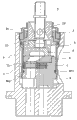
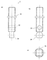
图1在纵剖面中(关闭的位置)显示了布置在带有侧向排出口的器具中的单手柄混合筒的示意性的图示; Figure 1 shows a schematic illustration of a single-handle mixing cartridge arranged in an appliance with a lateral outlet in longitudinal section (closed position);
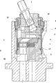
图2在打开的位置中显示了图1中的单手柄混合筒; Figure 2 shows the single handle mixing cartridge of Figure 1 in an open position;
图3显示了图1中的混合筒的头部件的示意性的图示 Figure 3 shows a schematic illustration of the head part of the mixing cartridge in Figure 1
a) 在纵剖面中 a) In longitudinal section
b) 在部分剖面中(旋转了90°), b) in partial section (rotated by 90°),
c) 在横截面中; c) in cross section;
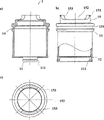
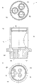
图4显示了图1中的混合筒的底部件的图示 Figure 4 shows a schematic representation of the bottom part of the mixing cylinder in Figure 1
a) 在俯视图中, a) In top view,
b) 在纵剖面中, b) in longitudinal section,
c) 在从下面的视图中, c) In the view from below,
d) 在b)中的图示的剖面D-D中, d) In the section D-D of the illustration in b),
e) 在侧视图中, e) In side view,
f) 在侧向视图中(旋转了90°), f) In side view (rotated 90°),
g) 在b)中的图示的剖面B-B中, g) In the section B-B of the illustration in b),
h) 在b)中的图示的剖面C-C中, h) In section C-C of the illustration in b),
i) 在b)中的图示的剖面A-A中; i) in section A-A of the illustration in b);
图5显示了图1中的混合筒的密封唇成形件的图示 Figure 5 shows an illustration of the sealing lip form of the mixing cartridge in Figure 1
a) 在俯视图中, a) In top view,
b) 在a)中的图示的剖面A-A中, b) In section A-A of the illustration in a),
c 在a)中的图示的剖面B-B中, c In section B-B of the illustration in a),
d) 在横截面中; d) in cross section;
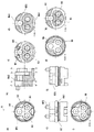
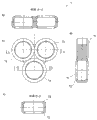
图6显示了图1中的混合筒的通过盘的图示 Figure 6 shows an illustration of the through disc of the mixing cartridge in Figure 1
a) 在从下面的视图中, a) In the view from below,
b) 在横截面中, b) In cross section,
c) 在俯视图中; c) in top view;
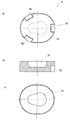
图7显示了图1中的混合筒的控制盘的图示 Figure 7 shows an illustration of the control panel of the mixing cartridge in Figure 1
a) 在从下面的视图中, a) In the view from below,
b) 在横截面中, b) In cross section,
c) 在俯视图中; c) in top view;
图8显示了图1中的混合筒的滑块的图示 Figure 8 shows an illustration of the slider of the mixing cylinder in Figure 1
a) 在从下面的视图中, a) In the view from below,
b) 在横截面中, b) In cross section,
c) 在俯视图中; c) in top view;
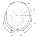
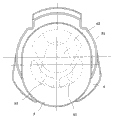
图9显示了在位置“关闭”中的带有控制盘和通过盘的图1中的混合筒的盘控制部; Figure 9 shows the disc control of the mixing cartridge of Figure 1 with the control disc and the pass-through disc in position "closed";
图10显示了在位置“混合水”中的图9中的盘控制部; Figure 10 shows the disc control of Figure 9 in position "mixed water";
图11显示了在位置“冷水”中的图9中的盘控制部; Figure 11 shows the pan control of Figure 9 in position "cold water";
图12显示了图1中的混合筒的心轴容纳部 Figure 12 shows the spindle housing of the mixing bowl in Figure 1
a) 在从下面的视图中, a) In the view from below,
b) 在横截面中, b) In cross section,
c) 在俯视图中; c) in top view;
图13显示了图1中的混合筒的心轴 Figure 13 shows the mandrel of the mixing bowl in Figure 1
a) 在侧视图中, a) In side view,
b) 在正视图中, b) In front view,
c) 在俯视图中; c) in top view;
图14显示了图1中的混合筒的固定环 Figure 14 shows the retaining ring of the mixing cylinder in Figure 1
a) 在剖示图中, a) In a cutaway view,
b) 在俯视图中以及 b) in top view and
图15显示了图1中的布置的器具 Figure 15 shows the appliance in the arrangement of Figure 1
a) 在从下面的视图中, a) In the view from below,
b) 在剖示图中, b) In a cutaway view,
c) 在俯视图中。 c) In top view.
具体实施方式 Detailed ways
选为实施例的单手柄混合筒主要包括头部件1,心轴2轴向地伸入其中,心轴2可摆动地支承在可旋转地支承的心轴容纳部3中并且接合滑块4中,滑块4与控制盘5相连接,控制盘5与通过盘6相对应,通过盘6经由密封成形件对底部件8密封。
The single-handle mixing bowl selected as an exemplary embodiment essentially comprises a
头部件1套筒式地来构造并且在实施例中作为黄铜旋转件(Messingdrehteil)来制造。在它的面向底部件8的端部处,在头部件1处在直径上彼此相对地模制有接片11,在其内侧处引入有卡锁槽111。在卡锁槽111之上,在头部件中在内环绕地模制有对底部件8的止挡12。在它的与接片11相对而置的端部处,头部件1具有环绕的、直径增大的凸肩13,用于容纳O形环17的槽131在中间环绕地引入其中。在凸肩14之上,布置有直径减小的截段15,在其处在端侧环绕地模制有鼻部151。两个凹口152在直径上彼此相对地引入直径减小的截段15中,通过凹口152分别形成两个径向的止挡153。止挡153用于心轴容纳部3的旋转限制。对于混合比应调节成恒定的实施形式,凹口152可实施为孔,心轴2的轴销(Achsstift)23接合到其中,由此锁止心轴容纳部3的旋转。
The
另外,固定环16盖到头部件1的直径减小的截段15上。固定环16在外面环绕地具有用于拧入器具9中的第一外螺纹161。在第一外螺纹161之上布置有直径减小的凸肩162,其设有第二外螺纹163。在端侧在固定环16处模制有直径减小的截段164,由其形成止挡165。直径减小的截段164在外面设有外六边形166。在它的与直径减小的截段164相对的端部处在内在固定环16中另外环绕地模制有鼻部167。
In addition, the
心轴2在实施例中大致方形地来构造。大约在中心在心轴2处模制有用于容纳未示出的操纵件的圆环形的同轴的模制部(Anformung)21。在该模制部21之下,通过心轴2引入用于容纳轴销23的孔22。在端侧以球形垫圈(Kugelscheibe)的形式构造的控制头24模制到心轴2处,其在它的面向滑块4的侧面处削平地来构造。
In the exemplary embodiment, the
心轴容纳部3构造为大致柱形的注塑件。在它的面向滑块4的端部处在心轴容纳部3处模制有两级的凸肩31,其轮廓相应于头部件1的两级的凸肩14的内轮廓,凸肩31贴靠在其处。在两级的凸肩31之上,通过心轴容纳部3引入用于容纳用于心轴2的轴销23的径向的通孔32。轴向地通过心轴容纳部3成型有用于心轴2的穿引部(Durchfuehrung)33,其具有侧向的止挡34,通过其来限制心轴2围绕轴销23的摆动半径。穿引部33通到大致方形地构造的用于滑块4的容纳部35中。
The
实施为注塑件的滑块4大致以圆盘的形式来构造,在其上模制有大致方形的模制件41。模制件41构造成使得其在心轴容纳部3的容纳部35内在纵向上可移动且在横向上来引导。轴向地通过滑块4穿过模制件41地引入用于容纳心轴2的控制头24的长孔42。在它的与模制件41相反的下侧处,在滑块4处在外环绕地另外模制有用于容纳控制盘5的三个轴向的接片43。
The
控制盘5椭圆地来构造并且作为陶瓷件来制造。在它的面向通过盘6的侧面处,控制盘具有布置在中间的、蛋状的凹入部(Einbuchtung)51。在它的与凹入部51相对的上侧上在控制盘5中在外环绕地另外引入有用于容纳滑块4的接片23的三个凹口52。经由凹口52,控制盘5与滑块4形状配合地相连接。
The
通过盘6同样实施为陶瓷件。通过通过盘6引入用于冷的或热的水的两个进入通道61以及用于混合水的相对于其增大地构造的排出通道62。进入通道61以及排出通道62倾斜于通过盘6地引导穿过其。在侧向上在通过盘6处彼此错置地引入有用于与底部件8形状配合地连接的三个凹部(Aussparung)63。
The
密封成形件7在实施例中由橡胶来制造。密封成形件7主要由三个环71形成,其分别模制在其余的两个环71处,从而形成三叶草式的轮廓。在密封成形件7的环71处,在其上侧处以及在其下侧处分别模制有密封唇72。为了使形状稳定化,环71分别设有支撑环73,其布置在环71的密封唇72之间。
The sealing
底部件8大致柱形地来构造。在底部件8中引入两个进入孔81以及排出孔82,其中轴线限制等腰的三角形。这两个进入孔81通到眼镜状地成型的凸肩83中,包围进入孔81地将用于容纳两个O形环的槽84引入其中。在侧向上在凸肩83中成型有槽831。与凸肩83相间隔地,另外在底部件8处模制有两个支脚85,其与凸肩83限制通道851并且其分别设有轴向的定位销852。支脚85布置成使得其与凸肩83限制排出孔82。由支脚85限制的通道851通到成型到凸肩83中的槽831中并且使能够有足够的进水量用于器具9的侧向的排出通道。
The
在侧向上在底部件8处环绕地模制有凸肩86,用于容纳头部件1的接片11的两个凹口861在直径上相对地引入其中。在凹口861的区域中模制有用于接合到头部件1的接片11的卡锁槽111中的卡锁鼻862。这些卡锁鼻862使在底部件8与头部件1之间的卡锁连接成为可能。在环绕的凸肩86之上,环绕地引入有用于容纳用于使底部件8相对于头部件1密封的O形环871的槽87。在它的与凸肩83相对而置的上侧上,底部件具有用于密封成形件7的三叶草状的容纳部88。环绕容纳部88,彼此均匀相间隔地模制有用于通过盘6的抗扭的容纳的三个接片89。接片89接合到通过盘6的凹部63中。为了改善形状配合,在两个接片89处模制有鼻部891,其接合到通过盘6的与此相对应的凹部63中。
A
器具9在图15中示意性地示出并且大致柱形地来构造。其具有筒容纳部91,在其敞开的端部处引入有用于拧入头部件1的固定环16的内螺纹92。在底部侧两个进水接口93以及排水接口94(其中轴线限制等腰三角形)通到筒容纳部91中。在排水接口94两侧,分别引入有用于容纳底部件8的定位销852的定位孔95。为了说明根据本发明的单手柄混合筒的应用可能性,另外设置有侧向的排水接口96。
The
在图9至11中示意性地示出了由控制盘5和通过盘6形成的盘控制部的不同位置。在根据图9的位置中,没有通过盘6的进入通道61被控制盘5的凹入部51遮盖。进入通道61因此被控制盘5封闭。不产生水通流(关闭的位置)。
The different positions of the disk control formed by the
在根据图10的盘控制部的位置中,用于热水和冷水的两个进入通道61被控制盘5的凹入部51遮盖,其同时还遮盖通过盘6的排出通道62。在混合水通过通过盘6的排出通道62流出之前,在控制盘5的凹入部51内发生热水和冷水的混合。在根据图11的盘控制部的位置中,仅仅一个进入通道61(这里冷水入口)被控制盘5的凹入部51遮盖,其将该进入通道61与通过盘6的排出通道62相连接。因此仅冷水从底部件8的排出通道82中流出。
In the position of the disc control according to FIG. 10 , the two
在图2中显示了根据图10的带有盘控制部的组件。混合水从底部件8的排出通道82通过通道851排出到在器具9的筒容纳部91与头部件1之间形成的间隙中并且由此到达器具9的排水接口94和96。根据器具的所希望的设计因此使能够通过排水接口96侧向去除混合水,以及使能够在底侧取出水。混合筒本身被从底部件8流出的水在器具9的筒容纳部91内围绕冲刷。通过布置在形成在头部件1的卡锁槽111与底部件8的卡锁鼻862之间的卡锁连接后面的O形环17有效地防止混合水进入在底部件8和布置在那里的控制模拟部后面的区域中。由塑料制成的底部件8的可能的变形被O形环吸收。通过由黄铜构造头部件1,尤其在底部件8的区域中避免头部件1的变形。
FIG. 2 shows the assembly according to FIG. 10 with the disk control. The mixed water drains from the
从底部件8的排出孔82中流出的水流的控制经由心轴2实现。心轴2围绕轴销23的摆动经由控制头24被传递到滑块4上以及到与滑块形状配合地连接的控制盘5上,由此引起水量的控制。心轴2的旋转经由轴销23被传递到在头部件1中可旋转地支承的心轴容纳部3上,其与滑块4经由模制件41形状配合地相连接。由此将旋转运动传递到滑块4上并且因此到与其形状配合地连接的控制盘5上并且引起存在于通过盘6的进入通道61处的水流的混合比的调节。
The control of the flow of water out of the outlet opening 82 of the
混合筒经由固定环16被与器具9相连接并且对筒容纳部91的底部预紧。由此获得的预紧力引起各个构件(尤其在滑块4、控制盘5、通过盘6和底部件8处)的制造公差的平衡。由此引起,可导致在一侧上的通过盘6以及在另一侧上的底部件8之间的对密封成形件7的不均匀的按压力。通过带有模制在其处的密封唇72的密封成形件7的弹性的构造,使密封成形件7在底部件8的容纳部88内的位置调整成为可能,由此确保可靠的密封效果。密封效果由以水在后面冲刷的密封唇72来支持。密封成形件7的环71的变形(其可导致损害密封效果)由在环71中引入的支撑环73来防止。
The mixing cartridge is connected to the
固定环16套放到头部件1的直径减小的截段15上,其中,环绕的鼻部151在经过固定环16的环绕的鼻部167时被弹性地向内挤。在经过固定环16的鼻部167之后,头部件1的直径减小的截段15的鼻部151又占据了其原始位置。固定环16因此防止丢失地保持在头部件1处。固定环16的拧入经由外六边形166实现。经由固定环16的第二外螺纹163使例如器具9的另一壳体件的固定成为可能。
The
Claims (10)
Applications Claiming Priority (3)
| Application Number | Priority Date | Filing Date | Title |
|---|---|---|---|
| EP20120157384 EP2634463B1 (en) | 2012-02-28 | 2012-02-28 | Single hand lever mixer cartridge |
| EP12157384.4 | 2012-02-28 | ||
| PCT/EP2013/052157 WO2013127601A1 (en) | 2012-02-28 | 2013-02-04 | Single-lever mixing cartridge |
Publications (2)
| Publication Number | Publication Date |
|---|---|
| CN103703295A true CN103703295A (en) | 2014-04-02 |
| CN103703295B CN103703295B (en) | 2016-12-07 |
Family
ID=47740909
Family Applications (1)
| Application Number | Title | Priority Date | Filing Date |
|---|---|---|---|
| CN201380001401.2A Expired - Fee Related CN103703295B (en) | 2012-02-28 | 2013-02-04 | Monolever mixing drum |
Country Status (9)
| Country | Link |
|---|---|
| US (1) | US9115819B2 (en) |
| EP (1) | EP2634463B1 (en) |
| KR (1) | KR102013965B1 (en) |
| CN (1) | CN103703295B (en) |
| AU (1) | AU2013225318B2 (en) |
| BR (1) | BR112013029791B1 (en) |
| MX (1) | MX336420B (en) |
| RU (1) | RU2602711C2 (en) |
| WO (1) | WO2013127601A1 (en) |
Families Citing this family (6)
| Publication number | Priority date | Publication date | Assignee | Title |
|---|---|---|---|---|
| CN105518360B (en) * | 2013-09-13 | 2017-09-22 | 弗吕斯旋转技术有限公司 | Singlehanded bar cylinder |
| DE202015100918U1 (en) | 2015-02-25 | 2015-03-27 | Flühs Drehtechnik GmbH | Single lever cartridge |
| ES2638404T3 (en) | 2015-02-25 | 2017-10-20 | Flühs Drehtechnik GmbH | Single lever cartridge |
| RU168591U1 (en) * | 2016-09-02 | 2017-02-09 | Общество с ограниченной ответственностью ПК "СВЕС" | SINGLE MIXING CARTRIDGE NUT |
| DE102017216413B3 (en) | 2017-09-15 | 2018-11-08 | Hansgrohe Se | Fluidumsteller |
| US11149418B2 (en) * | 2019-02-22 | 2021-10-19 | Brasstech, Inc. | Faucet handle hub |
Citations (6)
| Publication number | Priority date | Publication date | Assignee | Title |
|---|---|---|---|---|
| DE3518698A1 (en) * | 1985-05-24 | 1986-11-27 | Friedrich Grohe Armaturenfabrik Gmbh & Co, 5870 Hemer | Mixing valve for one-handed operation |
| US4887642A (en) * | 1987-10-27 | 1989-12-19 | Dorf Industries Pty. Ltd. | Single handle mixing tap or valve |
| US5095934A (en) * | 1991-04-16 | 1992-03-17 | Kohler Co. | Fluid valve |
| US5375624A (en) * | 1992-09-16 | 1994-12-27 | Masco Corporation Of Indiana | Cartridge for single-control faucet |
| CN2385175Y (en) * | 1999-07-05 | 2000-06-28 | 张家博 | Ceramic Disc of Feedwater Control Valve with Improved Structure |
| CN1671985A (en) * | 2002-08-19 | 2005-09-21 | 东陶机器株式会社 | disc valve |
Family Cites Families (8)
| Publication number | Priority date | Publication date | Assignee | Title |
|---|---|---|---|---|
| FI65659C (en) * | 1980-10-30 | 1984-06-11 | Oras Oy | ENGREPPSBLANDNINGSVENTIL |
| DE3419209C2 (en) * | 1984-05-23 | 1996-06-13 | Grohe Kg Hans | Mixing valve |
| IL73930A (en) * | 1984-12-25 | 1988-12-30 | Hamat Koor Metals Ltd | Mixing device for faucets |
| IT1213318B (en) * | 1986-07-31 | 1989-12-20 | Stella Rubinetterie Spa | SINGLE-LEVER MIXER TAP FOR WATER, WITH MEANS, FOR ADJUSTING THE END OF THE MIXING TEMPERATURE. |
| ITMI20022328A1 (en) * | 2002-10-31 | 2004-05-01 | Carlo Nobili S P A Rubinetterie | MIXING CARTRIDGE FOR SINGLE LEVER MIXER TAPS |
| US7032272B2 (en) * | 2003-03-27 | 2006-04-25 | Masco Corporation Of Indiana | Friction hinge |
| US6920899B2 (en) * | 2003-03-27 | 2005-07-26 | Masco Corporation Of Indiana | Fluid control valve |
| DE102008000108A1 (en) * | 2008-01-21 | 2009-07-23 | Ceramtec Ag | Cartridge for a sanitary fitting |
-
2012
- 2012-02-28 EP EP20120157384 patent/EP2634463B1/en active Active
-
2013
- 2013-02-04 BR BR112013029791-3A patent/BR112013029791B1/en not_active IP Right Cessation
- 2013-02-04 MX MX2013013232A patent/MX336420B/en unknown
- 2013-02-04 WO PCT/EP2013/052157 patent/WO2013127601A1/en not_active Ceased
- 2013-02-04 US US14/117,966 patent/US9115819B2/en active Active
- 2013-02-04 KR KR1020137028668A patent/KR102013965B1/en active Active
- 2013-02-04 RU RU2013151615/06A patent/RU2602711C2/en active
- 2013-02-04 AU AU2013225318A patent/AU2013225318B2/en not_active Ceased
- 2013-02-04 CN CN201380001401.2A patent/CN103703295B/en not_active Expired - Fee Related
Patent Citations (6)
| Publication number | Priority date | Publication date | Assignee | Title |
|---|---|---|---|---|
| DE3518698A1 (en) * | 1985-05-24 | 1986-11-27 | Friedrich Grohe Armaturenfabrik Gmbh & Co, 5870 Hemer | Mixing valve for one-handed operation |
| US4887642A (en) * | 1987-10-27 | 1989-12-19 | Dorf Industries Pty. Ltd. | Single handle mixing tap or valve |
| US5095934A (en) * | 1991-04-16 | 1992-03-17 | Kohler Co. | Fluid valve |
| US5375624A (en) * | 1992-09-16 | 1994-12-27 | Masco Corporation Of Indiana | Cartridge for single-control faucet |
| CN2385175Y (en) * | 1999-07-05 | 2000-06-28 | 张家博 | Ceramic Disc of Feedwater Control Valve with Improved Structure |
| CN1671985A (en) * | 2002-08-19 | 2005-09-21 | 东陶机器株式会社 | disc valve |
Also Published As
| Publication number | Publication date |
|---|---|
| MX336420B (en) | 2016-01-19 |
| BR112013029791A2 (en) | 2017-01-31 |
| RU2602711C2 (en) | 2016-11-20 |
| EP2634463A1 (en) | 2013-09-04 |
| EP2634463B1 (en) | 2014-05-14 |
| AU2013225318A1 (en) | 2013-11-07 |
| CN103703295B (en) | 2016-12-07 |
| AU2013225318B2 (en) | 2016-12-15 |
| US9115819B2 (en) | 2015-08-25 |
| US20140090722A1 (en) | 2014-04-03 |
| KR20140126659A (en) | 2014-10-31 |
| MX2013013232A (en) | 2014-05-27 |
| KR102013965B1 (en) | 2019-08-23 |
| BR112013029791B1 (en) | 2021-05-18 |
| WO2013127601A1 (en) | 2013-09-06 |
| RU2013151615A (en) | 2015-05-27 |
Similar Documents
| Publication | Publication Date | Title |
|---|---|---|
| CN103703295B (en) | Monolever mixing drum | |
| CN101646891B (en) | Valve cartridge with low point of contact for installation | |
| FI93051C (en) | Mixing valve for sanitary fittings | |
| US10436332B2 (en) | Fluid control valves | |
| US9958086B2 (en) | Faucet assembly | |
| US7182100B2 (en) | Retrofittable mixing valve and method of assembly | |
| US9931606B2 (en) | Single-lever mixing cartridge | |
| US20190017624A1 (en) | Low profile faucet handle assembly for a roman tub | |
| CN104321571B (en) | Monolever mixing socket | |
| US8109294B2 (en) | Valve cartridge with integral stop | |
| CN105190138B (en) | Singlehanded bar cylinder | |
| CN105980639A (en) | Fixture having a pivoting outlet | |
| KR890000449B1 (en) | Fluid control valve | |
| JP2020023825A (en) | Water spouting device | |
| CA3009969C (en) | Low profile faucet handle assembly for a roman tub | |
| HK1136859B (en) | Valve cartridge with low point of contact for installation |
Legal Events
| Date | Code | Title | Description |
|---|---|---|---|
| C06 | Publication | ||
| PB01 | Publication | ||
| C10 | Entry into substantive examination | ||
| SE01 | Entry into force of request for substantive examination | ||
| C14 | Grant of patent or utility model | ||
| GR01 | Patent grant | ||
| CF01 | Termination of patent right due to non-payment of annual fee |
Granted publication date: 20161207 |
|
| CF01 | Termination of patent right due to non-payment of annual fee |