CN103764458A - Device for the articulated connection of a wiper blade of flat bar construction to a wiper arm according to the side lock principle - Google Patents
Device for the articulated connection of a wiper blade of flat bar construction to a wiper arm according to the side lock principle Download PDFInfo
- Publication number
- CN103764458A CN103764458A CN201280035612.3A CN201280035612A CN103764458A CN 103764458 A CN103764458 A CN 103764458A CN 201280035612 A CN201280035612 A CN 201280035612A CN 103764458 A CN103764458 A CN 103764458A
- Authority
- CN
- China
- Prior art keywords
- wiper blade
- stop surface
- wiper
- insert
- water arm
- Prior art date
- Legal status (The legal status is an assumption and is not a legal conclusion. Google has not performed a legal analysis and makes no representation as to the accuracy of the status listed.)
- Pending
Links
Images


Classifications
-
- B—PERFORMING OPERATIONS; TRANSPORTING
- B60—VEHICLES IN GENERAL
- B60S—SERVICING, CLEANING, REPAIRING, SUPPORTING, LIFTING, OR MANOEUVRING OF VEHICLES, NOT OTHERWISE PROVIDED FOR
- B60S1/00—Cleaning of vehicles
- B60S1/02—Cleaning windscreens, windows or optical devices
- B60S1/04—Wipers or the like, e.g. scrapers
- B60S1/32—Wipers or the like, e.g. scrapers characterised by constructional features of wiper blade arms or blades
- B60S1/40—Connections between blades and arms
- B60S1/4067—Connections between blades and arms for arms provided with a side pin
- B60S1/4077—Connections between blades and arms for arms provided with a side pin characterised by the connecting part of, or an intermediate element mounted on, the wiper blade
-
- B—PERFORMING OPERATIONS; TRANSPORTING
- B60—VEHICLES IN GENERAL
- B60S—SERVICING, CLEANING, REPAIRING, SUPPORTING, LIFTING, OR MANOEUVRING OF VEHICLES, NOT OTHERWISE PROVIDED FOR
- B60S1/00—Cleaning of vehicles
- B60S1/02—Cleaning windscreens, windows or optical devices
- B60S1/04—Wipers or the like, e.g. scrapers
- B60S1/32—Wipers or the like, e.g. scrapers characterised by constructional features of wiper blade arms or blades
- B60S1/38—Wiper blades
- B60S1/3848—Flat-type wiper blade, i.e. without harness
- B60S1/3849—Connectors therefor; Connection to wiper arm; Attached to blade
- B60S1/3863—Connectors having a spoiler
Landscapes
- Engineering & Computer Science (AREA)
- Mechanical Engineering (AREA)
- Pivots And Pivotal Connections (AREA)
- Cleaning In General (AREA)
Abstract
Description
技术领域 technical field
本发明从按照权利要求1的前序部分所述的一种用于按照侧锁原理铰接式连接一呈扁梁结构形式的刮水片与一刮水臂的装置出发。 The invention proceeds from a device according to the preamble of claim 1 for the articulated connection of a wiper blade in the form of a flat beam to a wiper arm according to the side-lock principle.
背景技术 Background technique
从DE 100 36 135 A1中公开了一种用于车玻璃刮水器设备的车玻璃刮水器,其中,一呈扁梁结构形式的刮水片经由一联接元件与一刮水臂按照侧锁原理铰接式连接。所述刮水片具有一带有刮水唇的刮水板条,其中,作为承载元件设置两个侧部地安装在纵向凹槽中的、预弯曲的弹簧轨。在中部区域中,被分开的联接元件套装到所述弹簧轨的从所述纵向凹槽伸出的部分上,并且通过横向于所述刮水板条延伸的螺栓保持在一起。所述联接元件具有一轴承钻孔,在该轴承钻孔中可摆动地支承一侧部地从所述刮水臂伸出的轴承销。 From DE 100 36 135 A1 a windshield wiper for a windshield wiper device is disclosed, wherein a wiper blade in the form of a flat beam is connected to a wiper arm via a coupling element according to the side lock Principle Articulated connection. The wiper blade has a wiper strip with a wiper lip, wherein two pre-bent spring rails mounted laterally in longitudinal grooves are provided as carrier elements. In the central region, the divided coupling element is slipped onto the part of the spring rail protruding from the longitudinal groove and held together by bolts extending transversely to the wiper strip. The coupling element has a bearing bore in which a bearing pin protruding laterally from the wiper arm is pivotably mounted.
所述联接元件在面向所述刮水臂的侧面上还具有一保持指。其从所述刮水臂的与所述刮水板条相邻的侧面嵌入到所述刮水臂中。所述刮水臂至少在所述联接元件的区域中具有一u形的横截面,其朝所述刮水板条敞开,从而所述保持指能够从后面嵌接所述刮水臂的与所述联接元件相邻的翼部。所述保持指相对于所述轴承销朝驱动端部错开,从而通过所述刮水片相对于所述刮水臂的摆动运动,使得所述保持指脱离嵌接,而所述保持指在运行位置中沿着所述轴承销的方向确保所述刮水片的位置,在所述运行位置中所述刮水臂的端部侧部地平行于所述刮水片延伸。 The coupling element also has a retaining finger on the side facing the wiper arm. It engages in the wiper arm from the side of the wiper arm adjacent to the wiper strip. The wiper arm has a u-shaped cross section at least in the region of the coupling element, which is open towards the wiper strip, so that the retaining finger can engage behind the wiper arm with the adjacent wings of the coupling element. The retaining fingers are offset relative to the bearing pin towards the drive end, so that due to the pivoting movement of the wiper blade relative to the wiper arm, the retaining fingers are disengaged while the retaining fingers are running In the direction of the bearing pin, a position of the wiper blade is ensured in which the end of the wiper arm extends laterally parallel to the wiper blade in the operating position.
发明内容 Contents of the invention
按照本发明,所述保持指具有一鼻部,该鼻部相对于所述保持指的面向所述轴承销的端面伸出并且具有一指向所述刮水板条的止挡面。该止挡面与一其它的、处于与所述刮水臂的相对摆动区域中的止挡面配合作用,该止挡面设置在所述刮水臂上,其中,在所述刮水片的运行位置中,所述两个止挡面在它们之间围出一摆动角,在该摆动角的范围中,无法进行所述刮水片沿着所述轴承销的方向的拆卸或安装。如果将用于清洁所述刮水片的车玻璃刮水器从机动车玻璃上取下,则所述刮水片无法意外地相对于所述刮水臂摆动到拆卸位置且因此无法从所述轴承销上脱开。 According to the invention, the retaining finger has a nose which protrudes relative to the end face of the retaining finger facing the bearing pin and has a stop surface directed towards the wiper strip. This stop surface cooperates with a further stop surface which is arranged on the wiper arm in the region of the pivoting relative to the wiper arm, wherein the wiper blade In the operating position, the two stop surfaces enclose between them a pivot angle in the range of which the wiper blade cannot be removed or mounted in the direction of the bearing pin. If the windshield wiper for cleaning the wiper blade is removed from the motor vehicle windshield, the wiper blade cannot be accidentally pivoted into the dismounted position relative to the wiper arm and thus cannot be removed from the The bearing pins are disengaged.
根据本发明的一种设计方案,在具有一朝所述刮水板条敞开的、u形轮廓的刮水臂的情况下,其中,所述保持指嵌入到所述轮廓中,一插入件端面地插入到所述u形的横截面轮廓中,在所述插入件上设置有配属于所述刮水臂的止挡面。通过所述插入件,其适宜地由塑料在一注射成型方法中制造,可以将配属于所述刮水臂的止挡面以简单的方式与不同的刮水片相适配。同时,所述插入件可以一正面的端壁端面地封闭所述u形轮廓,其方式为,所述端壁以一凸台贴靠在所述刮水臂的端面上。 According to an embodiment of the invention, in the case of a wiper arm with a U-shaped profile which is open towards the wiper strip, wherein the retaining fingers engage in the profile, an insert end face Inserted into the u-shaped cross-sectional profile, a stop surface assigned to the wiper arm is arranged on the insert. By means of the insert, which is advantageously produced from plastic in an injection molding process, the stop surface associated with the wiper arm can be adapted in a simple manner to different wiper blades. At the same time, the insert part can end-face the u-shaped profile with a front end wall in that the end wall rests with a cam on the end face of the wiper arm.
根据本发明的一种设计方案,所述插入件以一横向钻孔坐放在所述轴承销的在所述刮水臂中延伸的部分上。为了能够简单地安装所述插入件,适宜的是,所述横向钻孔朝所述保持指的鼻部敞开,其中,所述插入件利用所述横向钻孔坐放在所述轴承销上,其中,所述开口构造成夹子,从而所述插入件可从所述刮水臂的敞开的端面夹到所述轴承销上。所述止挡面布置在所述夹子的平躺在所述刮水板条上的部分上。 According to one refinement of the invention, the insert part rests with a transverse bore on the part of the bearing pin extending in the wiper arm. In order to be able to easily mount the insert, it is expedient if the transverse bore is open towards the nose of the retaining finger, wherein the insert rests on the bearing pin by means of the transverse bore, In this case, the opening is designed as a clip, so that the insert can be clipped onto the bearing pin from the open end face of the wiper arm. The stop surface is arranged on that part of the clip which lies on the wiper strip.
本发明的另一种设计方案能够实现,为了拆卸所述刮水片无需将所述插入件从所述刮水臂中去除。在此情况下,在所述插入件的正端壁的指向内的侧面上紧固一折角的弹簧夹板,其自由的翼部指向所述刮水臂的驱动侧的端部并且具有一用作止挡面的端部棱边。当所述刮水片在安装时被转动到所述运行位置中时,所述鼻部回压所述弹簧夹板的自由翼部,所述自由翼部在适配所述鼻部之后回弹到起始位置中并且以其端部棱边与所述鼻部的止挡面配合作用。为此适宜的是,所述鼻部在其背离所述刮水板条的侧面上相对于所述联接元件的纵向倾斜地延伸,其中,该侧面与所述鼻部的止挡面在一共同的棱边中相遇。 A further refinement of the invention makes it possible that the insert does not have to be removed from the wiper arm in order to remove the wiper blade. In this case, on the inwardly pointing side of the front end wall of the insert, an angled spring clip is fastened, the free wing of which points toward the drive-side end of the wiper arm and has a function as End edge of the stop surface. When the wiper blade is turned into the operating position during installation, the nose presses back against the free wings of the spring clip, which spring back to the In the starting position and with its end edges it cooperates with the stop surface of the nose. For this purpose, it is expedient for the nose to run obliquely with respect to the longitudinal direction of the coupling element on its side facing away from the wiper strip, wherein the side faces a common stop surface of the nose. meet at the edge.
在本发明的另一种设计方案中,所述插入件的从动侧的正面的端壁和驱动侧的端壁将两个侧壁相互连接起来,其中,在所述侧壁的指向所述刮水板条的边缘上布置一横向地延伸的弹簧连接件,其用作刮水臂侧的止挡面,其中,所述横向钻孔相对于所述边缘朝所述从动侧的端部错开。所述弹簧连接件的挠性和弹性可以通过切口来修改,这些切口沿着朝所述弹簧连接件的两个侧面的纵向设置在侧壁中。在该情况下适宜的是,所述止挡面在所述鼻部上利用背离所述刮水板条的侧面倾斜地延伸且因此形成一楔形的横截面。通过倾斜的面能够实现,所述弹簧连接件在安装和拆卸时可利用一提高的操作力适配所述鼻部。 In another embodiment of the present invention, the front end wall on the driven side and the end wall on the driving side of the insert connect the two side walls to each other, wherein the A transversely extending spring connection is arranged on the edge of the wiper strip, which serves as a stop surface on the wiper arm side, wherein the transverse bore is opposite the end of the edge towards the output side stagger. The flexibility and elasticity of the spring connection can be modified by means of cutouts which are provided in the side walls in the longitudinal direction towards both sides of the spring connection. In this case it is expedient if the stop surface runs obliquely on the nose with the side facing away from the wiper strip and thus forms a wedge-shaped cross section. The inclined surface makes it possible for the spring connection to be adapted to the nose with an increased actuating force during installation and removal.
不仅要求保护一种装置,其包括一刮水片和一刮水臂,而且也要求保护一种具有相应的联接元件的刮水片,该联接元件的保持指在其从动侧的端面上具有一指向开口的鼻部,该鼻部具有一对准所述刮水板条的止挡面,或者该鼻部朝向所述开口楔形地延伸。 Not only is a device claimed which comprises a wiper blade and a wiper arm, but also a wiper blade with a corresponding coupling element whose retaining fingers have on their driven-side end faces A nose pointing toward the opening, which has a stop surface aligned with the wiper strip, or which extends wedge-shaped towards the opening.
针对本发明而言,是否所述联接元件是一件式地或是多件式地实施,或者包括一遮盖罩,在该遮盖罩上布置所述保持指,都是无关紧要的。 For the purposes of the invention, it is immaterial whether the coupling element is embodied in one piece or in multiple parts, or comprises a cover on which the retaining fingers are arranged.
同样地,要求保护一种作为单个构件的插入件,其中,其横向钻孔构造成夹子,并且在所述刮水臂的区域中夹在所述轴承销上。在该情况下,所述止挡面布置在所述夹子的面向所述刮水唇的部分上。在另一种实施方式中,所述插入件的止挡面可以通过一紧固在所述正面的端壁上的弹簧夹板形成,或通过一在所述插入件的侧壁之间的弹簧连接件形成。 Likewise, an insert is claimed as a single component, wherein its transverse bore is configured as a clip and clamped on the bearing pin in the region of the wiper arm. In this case, the stop surface is arranged on that part of the clip facing the wiper lip. In a further embodiment, the stop surface of the insert can be formed by a spring clip fastened on the front end wall, or by a spring connection between the side walls of the insert pieces formed.
附图说明 Description of drawings
其它优点从下面的附图描述中给出。在附图中展示了本发明的实施例。附图、说明书和权利要求书包含了大量的特征组合。本领域技术人员也可以合理地将这些特征单独考虑或者适宜地总结出其它组合。 Further advantages emerge from the following description of the figures. Embodiments of the invention are shown in the drawings. The drawings, the description and the claims contain numerous combinations of features. Those skilled in the art can also reasonably consider these features individually or appropriately summarize other combinations.
其中: in:
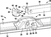
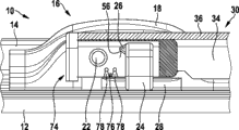
图1 示出了在安装时的按照本发明的装置作为分解图的立体部分视图, Fig. 1 shows the perspective partial view of the device according to the invention as an exploded view when installed,
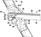
图2 示出了在一运行位置中的按照图1的安装好的装置的侧视图, Figure 2 shows a side view of the installed device according to Figure 1 in an operating position,
图3 示出了具有一纵向相交的刮水臂的立体部分视图, Figure 3 shows a perspective partial view with a longitudinally intersecting wiper arm,
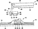
图4 示出了图1的一种变型, Figure 4 shows a variant of Figure 1,
图5 示出了在一运行位置中的具有一纵向相交的刮水臂的按照图4的变型, FIG. 5 shows the variant according to FIG. 4 with a longitudinally intersecting wiper arm in an operating position,
图6 示出了图1的另一种变型, Figure 6 shows another variant of Figure 1,
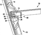
图7 示出了在一运行位置中的具有一纵向相交的刮水臂的按照图6的变型的侧视图,以及 FIG. 7 shows a side view of the variant according to FIG. 6 with a longitudinally intersecting wiper arm in an operating position, and
图8 示出了具有一相对于所述刮水臂摆动的刮水片的按照图6的变型的立体部分视图。 FIG. 8 shows a perspective partial view of the variant according to FIG. 6 with a wiper blade pivoted relative to the wiper arm.
具体实施方式 Detailed ways
用于按照侧锁原理铰接式连接一呈扁梁结构形式的刮水片10与一刮水臂30的装置基本上包括一紧固在所述刮水片10上的带有一遮盖罩18的联接元件16,和一轴承销38以及呈不同的实施方式的插入件40、60、74。所述呈扁梁结构形式的刮水片10具有一刮水板条12,其通常被以一个或多个弹簧轨为形式的承载元件保持住,但所述弹簧轨在附图中不可见。在所述弹簧轨上紧固所述联接元件16。扰流板14沿着纵向朝所述联接元件16的两侧在所述弹簧轨上引导。
The device for the articulated connection of a
所述刮水臂30的指向所述联接元件16的端部具有一u形的横截面轮廓,其由两个侧壁32、34和一连接所述两个侧壁的盖壁36形成。在所述运行位置(图2)中,所述刮水臂30侧部地大致平行于所述刮水片10延伸。所述轴承销38横穿所述刮水臂30的u形横截面轮廓,并且在其侧壁32、34中紧固,其中,所述轴承销从与所述联接元件16相邻的侧壁34向外伸出。所述轴承销38的伸出部分通过所述遮盖罩18中的一开口22被推入到所述联接元件16的一不可见的轴承钻孔中。为此,所述刮水臂30必须相对于所述刮水片10占据这样一个角度位置,使得与所述联接元件16相邻的侧壁34的自由棱边在一保持指24旁经过。所述保持指24朝所述刮水片10的驱动侧的端部相对于所述开口22错开,并且以与所述遮盖罩18的侧壁20的间距经由一连接件28与其连接。在所述连接件28的区域中,与所述联接元件16相邻的侧壁34具有一凹部58,从而所述刮水臂30在所述运行位置中在其摆动运动上不受阻。此外,所述保持指24在其从动侧的端面上具有一鼻部26,该鼻部对准所述遮盖罩18的开口22或者说所述轴承销38并且具有一指向所述刮水板条12的止挡面56。
The end of the
在所述刮水臂30回摆到所述运行位置中的情况下,所述保持指24从后面嵌接与所述联接元件16相邻的侧壁34,从而所述刮水片10沿着所述轴承销38的纵向相对于所述刮水臂30保持住。为了使当所述刮水片10从所述车玻璃上取下时,所述刮水片不会不被察觉地从所述轴承销38上脱开,安装所述插入件40。该插入件从所述端面被推入到所述刮水臂30的u形横截面中,直到其端壁42以一凸台44贴靠在所述刮水臂30的端面上。在该位置中,将所述插入件40以一本体46在所述u形的横截面轮廓中引导,并且经由一横向钻孔48紧固在所述轴承销38的在所述刮水臂30中延伸的部分上。为此,所述横向钻孔48朝所述轴承销38敞开,其中,所述开口构造成夹子50,从而所述插入件40可脱开地紧固在所述轴承销38上。在所述本体46的面向所述刮水板条12的部分上,设置一止挡面54,该止挡面处于一相对于所述保持指24的鼻部26上的止挡面56的摆动区域中。所述两个止挡面54和56允许所述刮水片10相对于所述刮水臂30的一摆动角α,该摆动角小于为了拆卸所需的摆动角。
When the
在按照图4的实施方式中,所述插入件60具有一从动侧的端面62和一驱动侧的端壁68,它们将两个侧壁64、66相互连接起来。在所述侧壁64、66中设置用于所述轴承销38的横向钻孔70。所述端壁62与所述侧壁64、66形成一凸台44,利用该凸台,所述端壁62如同在按照图1的实施例中的端壁42那样贴靠在所述刮水臂30的端面52上。所述端壁62、68的间距如此定尺寸,使得在所述间隙中保留用于所述保持指24的足够的位置。
In the embodiment according to FIG. 4 , the
在所述端壁62上紧固一弯角的弹簧夹板72,其自由翼部对准所述驱动侧的端部,并且在安装好的状态下从所述刮水板条12的侧面遮盖所述轴承销38。所述弹簧夹板72的自由翼部的自由边棱在该情况下形成所述止挡面54,该止挡面与所述保持指24的鼻部26上的止挡面56配合作用。通过所述弹簧夹板72的自由翼部的挠性,所述弹簧夹板可以经由所述鼻部26的倾斜地延伸的、背离所述刮水板条12的侧面被向回推并且随后又反锁住。在拆卸时将所述弹簧夹板72手动地向回挤压。
An
按照图6至8的实施例的插入件74类似于按照前面的实施例的插入件74。其同样具有一从动侧的端壁62和一驱动侧的端壁68,它们将两个侧壁64、66相互连接。不同之处在于,代替所述弹簧夹板72设置一弹簧连接件76,其相对于所述横向钻孔70在驱动侧错开地将两个侧壁64、66连接起来。沿着朝所述弹簧连接件76的两个侧面的纵向,在所述侧壁64、66的指向所述刮水板条12的边缘中布置切口78,通过所述切口能够修改所述弹簧连接件76的弹簧弹性,其中,所述侧面形成所述止挡面54。
The
Claims (15)
Applications Claiming Priority (3)
| Application Number | Priority Date | Filing Date | Title |
|---|---|---|---|
| DE102011079486.7A DE102011079486B4 (en) | 2011-07-20 | 2011-07-20 | Device for the articulated connection of a wiper blade in flat bar construction with a wiper arm according to the sidelock principle |
| DE102011079486.7 | 2011-07-20 | ||
| PCT/EP2012/063263 WO2013010821A1 (en) | 2011-07-20 | 2012-07-06 | Device for the articulated connection of a wiper blade of flat bar construction to a wiper arm according to the side lock principle |
Publications (1)
| Publication Number | Publication Date |
|---|---|
| CN103764458A true CN103764458A (en) | 2014-04-30 |
Family
ID=46466547
Family Applications (1)
| Application Number | Title | Priority Date | Filing Date |
|---|---|---|---|
| CN201280035612.3A Pending CN103764458A (en) | 2011-07-20 | 2012-07-06 | Device for the articulated connection of a wiper blade of flat bar construction to a wiper arm according to the side lock principle |
Country Status (4)
| Country | Link |
|---|---|
| EP (1) | EP2734422A1 (en) |
| CN (1) | CN103764458A (en) |
| DE (1) | DE102011079486B4 (en) |
| WO (1) | WO2013010821A1 (en) |
Families Citing this family (3)
| Publication number | Priority date | Publication date | Assignee | Title |
|---|---|---|---|---|
| FR3031712B1 (en) * | 2015-01-16 | 2018-10-12 | Valeo Systemes D'essuyage | ICE WIPER COVER CONFIGURE TO COVER A TERMINAL PART OF A WIPER ARM |
| FR3043041B1 (en) * | 2015-11-04 | 2017-12-08 | Valeo Systemes Dessuyage | ADAPTER FOR A WINDSCREEN WIPER OF A MOTOR VEHICLE |
| FR3043042B1 (en) * | 2015-11-04 | 2017-12-15 | Valeo Systemes Dessuyage | ADAPTER FOR A WINDSCREEN WIPER OF A MOTOR VEHICLE |
Citations (9)
| Publication number | Priority date | Publication date | Assignee | Title |
|---|---|---|---|---|
| US4114227A (en) * | 1976-06-08 | 1978-09-19 | Arman S.P.A. | Connection between a windshield wiper blade and the oscillating arm carrying it |
| CN1310679A (en) * | 1999-05-28 | 2001-08-29 | 罗伯特·博施有限公司 | Wiper device for motor vehicle windows |
| DE10036135A1 (en) * | 2000-07-25 | 2002-02-28 | Volkswagen Ag | Vehicle windscreen wiper has blade holding block with bearing for pivot bolt and securing hook |
| DE10259477A1 (en) * | 2002-12-19 | 2004-07-01 | Robert Bosch Gmbh | Prevention arrangement of a wiper device for windows of motor vehicles |
| DE102004017941A1 (en) * | 2004-04-14 | 2005-11-03 | Robert Bosch Gmbh | Device for connecting wiper blade with wiper arm has securing device with at least one securing part protruding from wiper blade on wiper blade side with toggle bar locking device |
| DE202005020549U1 (en) * | 2005-10-21 | 2006-04-20 | Robert Bosch Gmbh | Wiper arm and wiper blade connection device for motor vehicle, has attachment part with retainer for taking up securing unit, where longitudinal molding e.g. groove, is provided in securing unit parallel to joint axis |
| EP1745998A1 (en) * | 2005-07-18 | 2007-01-24 | Federal-Mogul S.A. | Windscreen wiper device |
| CN101203411A (en) * | 2005-04-29 | 2008-06-18 | 法雷奥系统公司 | Arrangement for mounting the wiper blade to the end of the drive arm |
| WO2010028918A1 (en) * | 2008-09-11 | 2010-03-18 | Robert Bosch Gmbh | Device for the articulated connection of a wiper blade to a wiper arm of a windshield wiper |
-
2011
- 2011-07-20 DE DE102011079486.7A patent/DE102011079486B4/en not_active Expired - Fee Related
-
2012
- 2012-07-06 EP EP12733127.0A patent/EP2734422A1/en not_active Withdrawn
- 2012-07-06 WO PCT/EP2012/063263 patent/WO2013010821A1/en not_active Ceased
- 2012-07-06 CN CN201280035612.3A patent/CN103764458A/en active Pending
Patent Citations (9)
| Publication number | Priority date | Publication date | Assignee | Title |
|---|---|---|---|---|
| US4114227A (en) * | 1976-06-08 | 1978-09-19 | Arman S.P.A. | Connection between a windshield wiper blade and the oscillating arm carrying it |
| CN1310679A (en) * | 1999-05-28 | 2001-08-29 | 罗伯特·博施有限公司 | Wiper device for motor vehicle windows |
| DE10036135A1 (en) * | 2000-07-25 | 2002-02-28 | Volkswagen Ag | Vehicle windscreen wiper has blade holding block with bearing for pivot bolt and securing hook |
| DE10259477A1 (en) * | 2002-12-19 | 2004-07-01 | Robert Bosch Gmbh | Prevention arrangement of a wiper device for windows of motor vehicles |
| DE102004017941A1 (en) * | 2004-04-14 | 2005-11-03 | Robert Bosch Gmbh | Device for connecting wiper blade with wiper arm has securing device with at least one securing part protruding from wiper blade on wiper blade side with toggle bar locking device |
| CN101203411A (en) * | 2005-04-29 | 2008-06-18 | 法雷奥系统公司 | Arrangement for mounting the wiper blade to the end of the drive arm |
| EP1745998A1 (en) * | 2005-07-18 | 2007-01-24 | Federal-Mogul S.A. | Windscreen wiper device |
| DE202005020549U1 (en) * | 2005-10-21 | 2006-04-20 | Robert Bosch Gmbh | Wiper arm and wiper blade connection device for motor vehicle, has attachment part with retainer for taking up securing unit, where longitudinal molding e.g. groove, is provided in securing unit parallel to joint axis |
| WO2010028918A1 (en) * | 2008-09-11 | 2010-03-18 | Robert Bosch Gmbh | Device for the articulated connection of a wiper blade to a wiper arm of a windshield wiper |
Also Published As
| Publication number | Publication date |
|---|---|
| WO2013010821A1 (en) | 2013-01-24 |
| EP2734422A1 (en) | 2014-05-28 |
| DE102011079486B4 (en) | 2020-09-24 |
| DE102011079486A1 (en) | 2013-01-24 |
Similar Documents
| Publication | Publication Date | Title |
|---|---|---|
| US9096196B2 (en) | Wiper blade | |
| CN102574501B (en) | Windshield wiper assembly with optimized wings | |
| KR101279754B1 (en) | Windscreen wiper device | |
| CN102149581B (en) | Device for hingedly connecting wiper blades and wiper arms of wipers | |
| CN100554049C (en) | wiper blade | |
| CN100548758C (en) | Wiper unit with flat wiper blade and wiper arm | |
| US8505151B2 (en) | Connecting device for the articulated connection of a wiper blade to a wiper arm | |
| US7971312B2 (en) | Connecting element for wiper | |
| US9387830B2 (en) | Connecting device for the articulated connection of a wiper blade to a wiper arm, and an adaptor | |
| CN101980903B (en) | windshield wiper unit | |
| RU2509669C2 (en) | Wiper brush hinge | |
| CN101189148B (en) | Device for the articulated connection of a wiper blade to a wiper arm of a windshield wiper | |
| JP2003503275A (en) | Wiper blade for automotive window glass with an elongated spring-elastic support element | |
| US20100017994A1 (en) | Windshield wiper device | |
| CN103370236A (en) | Wiper blade and end cap | |
| CN104114419A (en) | Windscreen wiper device | |
| JP4418840B2 (en) | Wiper blade | |
| CN103974859B (en) | windshield wiper arm | |
| US20100275403A1 (en) | Windscreen wiper device | |
| CN1989032B (en) | Connection device for wiper arm | |
| CN103764458A (en) | Device for the articulated connection of a wiper blade of flat bar construction to a wiper arm according to the side lock principle | |
| CN103228497B (en) | Wind shield wiper | |
| CN103987590B (en) | Windscreen wiper device | |
| EP2790970B1 (en) | Windscreen wiper arm | |
| US20160016554A1 (en) | Top-lock wiper blade adapter |
Legal Events
| Date | Code | Title | Description |
|---|---|---|---|
| C06 | Publication | ||
| PB01 | Publication | ||
| C10 | Entry into substantive examination | ||
| SE01 | Entry into force of request for substantive examination | ||
| WD01 | Invention patent application deemed withdrawn after publication |
Application publication date: 20140430 |
|
| WD01 | Invention patent application deemed withdrawn after publication |