CN103802155A - Film cutting processing method with stable film cutting speed - Google Patents
Film cutting processing method with stable film cutting speed Download PDFInfo
- Publication number
- CN103802155A CN103802155A CN201210439470.9A CN201210439470A CN103802155A CN 103802155 A CN103802155 A CN 103802155A CN 201210439470 A CN201210439470 A CN 201210439470A CN 103802155 A CN103802155 A CN 103802155A
- Authority
- CN
- China
- Prior art keywords
- film
- knife
- cutting
- acceleration
- processing method
- Prior art date
- Legal status (The legal status is an assumption and is not a legal conclusion. Google has not performed a legal analysis and makes no representation as to the accuracy of the status listed.)
- Granted
Links
Images


Landscapes
- Control Of Cutting Processes (AREA)
- Perforating, Stamping-Out Or Severing By Means Other Than Cutting (AREA)
Abstract
A film cutting method for stabilizing film cutting speed features that when a film is moved back and forth along a cutting path relative to a machine seat, a base paper on said machine seat is instantaneously accelerated by drive unit to reach the film cutting speed for cutting and then restored to initial speed.
Description
Technical field
The present invention relates to a kind of stabilising membrane and cut the film cutting processing method of speed, espespecially a kind of processing method of cutting machine knife film the film of base stock plane materiel is cut speed in order to stabilising membrane.
Background technology
Generally speaking, self-stick notes (base stock) complete plane materiel printing and plane materiel to the after tack of release liners (ground) after, processer need to utilize film to cut machine and further cut with facestock, still do not go to cut to release liners to leave the cutting vestige of tearable property on plane materiel, this is film and cuts, can make user in the future can be freely by with print pattern, the plane materiel of printed words is torn from release liners, general film is cut the many belows that base stock are positioned over to cutter film of processing, and making base stock comply with a set direction carries, in the process of conveying base stock, make film cut machine band moving knife film moves up and down simultaneously, with compartment of terrain, the base stock in carrying being carried out to film cuts.
But as shown in Figure 1A, Figure 1B and 1C, its Y-axis is that film is cut speed (inferior/1/10th second), represent the speed that cutter film moves up and down, X-axis is time (second), conventional film is cut machine knife film motion mode and the film thereof of work piece (referring to include the base stock of plane materiel and release liners) is cut in process, only merely tool setting film imposes linear acceleration and linear deceleration, even at fixing 10000RPM, under the rotating speed of 12000RPM or 250RPM, still it is unstable that the film that can find cutter film is cut speed drift, therefore no matter at cutter film low-speed running or while running up, cutter film is inconsistent to the moment impact of work piece, therefore it is not identical that cutter film touches the instantaneous pressure of work piece, and then cause the finished product state of work piece inconsistent or at all cannot effectively cut, this problem of failing to carry out effectively cutting is produced while only reaching 250RPM to 3000RPM as motor rotary speed especially obvious at low speed, and even therefore school machine complete or low speed produce after when high-speed production, still need to adjust the pressure of cutter film to work piece, make cutter film in the time that work piece is cut, cause suitable or more consistent extruding, to reach effective cutting and to make the Yield lmproved of finished product, but above-mentioned extruding is related to cutter film in fact, the mill of work piece is pressed, mill is cut (after friction, cutting), therefore belonging to external force that is comparatively coarse and violence applies, this is external carries out film when cutting, base stock is also carried toward a throughput direction constantly, known mode more can overstay by cutter relieving film in work piece, still have greatly and may in extrusion process, cause the life-span of cutter film to shorten if deal with improperly, or cause cut place to produce the result that the finished product yields such as fold decline.
So the problem that inventor's thoughts are above-mentioned, is that spy concentrates on studies and coordinates the utilization of scientific principle, finally propose a kind of reasonable in design and effectively improve the present invention of above-mentioned defect.
Summary of the invention
Object of the present invention, the film cutting processing method that provides a kind of stabilising membrane to cut speed is provided, the film of work piece is cut to speed film unstable and that cause is cut into that product are inconsistent, yield declines or even cannot carry out the effectively problem of cutting to solve cutter film.
For achieving the above object, the invention provides a kind of stabilising membrane and cut the film cutting processing method of speed, with so that a cutter film while moving back and forth along a cutting path with respect to a processing seat, can stably bestow this film to the base stock on this processing seat and cut speed to cut, this base stock comprises a plane materiel and a release liners, on this plane materiel, compartment of terrain planning has multiple point of contacts for the treatment of, this base stock is accepted this cutter film along a throughput direction conveying with compartment of terrain constantly this is treated to the cutting at point of contact on this processing seat, the film cutting processing method that this stabilising membrane is cut speed comprises the steps: to provide a gear unit, this gear unit moves back and forth along this cutting path in order to this cutter film of interlock, provide in order a cutter film motion starting point, a cutter film to accelerate starting point, a cutter film acceleration summit and a cutter film at this cutting path and accelerate terminal, this gear unit is with so that this cutter film accelerates starting point, this cutter film and accelerates the direction that summit and this cutter film accelerate terminal and move along move starting point, this cutter film of this cutter film in order, and this cutter film accelerates terminal from this cutter film again and gets back to this cutter film motion starting point and complete this cutter film moving along this cutting path, when this cutter film is positioned at this cutter film acceleration starting point, start the running to this gear unit, accelerate to this film from a starting velocity and cut speed, when this cutter film is positioned at this cutter film acceleration summit, the running of this gear unit accelerates to this film and cuts speed, and this cutter film is when being positioned at this cutter film and accelerating terminal, the running of this gear unit returns to this starting velocity.
Pass through this method, the in the situation that of can no matter being low speed production or high-speed production, make cutter film be about to base stock is cut before, make cutter film the film speed of cutting can because of gear unit moment accelerate relation, and be stably controlled, remain on a required speed, grind the action of cutting or grinding pressure and needn't make cutter film do on base stock more, so can impel cutter film to reach effective cutting and promote film and be cut into the yield of product, and because film is cut velocity-stabilization and can be reduced the unnecessary wearing and tearing of cutter film, effectively extend the service life of cutter film.
For enabling further to understand feature of the present invention and technology contents, refer to following about detailed description of the present invention and accompanying drawing, but appended graphic only provide with reference to and explanation use, be not used for the present invention to be limited.
Accompanying drawing explanation
Figure 1A is the movement velocity sampled data curve map that known membrane is cut cutter film under cooked mode in the time of 10000RPM;
Figure 1B is the movement velocity sampled data curve map that known membrane is cut cutter film under cooked mode in the time of 12000RPM;
Fig. 1 C is the movement velocity sampled data curve map that known membrane is cut cutter film under cooked mode in the time of 250RPM;
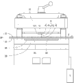
Fig. 2 carries out stabilising membrane of the present invention motion schematic diagram between cutter film and processing seat while cutting the film cutting processing method of speed;
Fig. 3 A is the cutter film movement velocity sampled data curve map of film cutting processing method in the time of 3000RPM that stabilising membrane of the present invention is cut speed;
Fig. 3 B is the cutter film movement velocity sampled data curve map of film cutting processing method in the time of 9000RPM that stabilising membrane of the present invention is cut speed;
Fig. 4 A be carry out stabilising membrane of the present invention while cutting the film cutting processing method of speed film cut the gear unit schematic diagram of machine;
Fig. 4 B be carry out stabilising membrane of the present invention while cutting the film cutting processing method of speed film cut the gear unit cutaway view of machine; And
Fig. 5 is the flow chart of steps that stabilising membrane of the present invention is cut the film cutting processing method of speed.
[main element symbol description]
10 tool rests
11 cutter films
111 cutter film seats
20 processing seats
22 processing seat bottom bars
30 base stocks
31 plane materiels
32 release liners
33 treat point of contact
40 mend material
50 first eccentric drive shafts
51 first gears
52 first eccentric parts
60 second eccentric drive shafts
61 connectors
62 second eccentric parts
70 axostylus axostyles
80 final drive shafts
81 master gears
A1, A4, B1, B4 accelerate starting point
Velocity peak values after A2, A5, B2, B5 accelerate
A3, A6, B3, B6 accelerate terminal
F paper feeding direction
P cutting path
P1 cutter film motion starting point
P11 cutter film accelerates starting point
P12 cutter film accelerates terminal
P2 cutter film accelerates summit
S1 the first servo motor
S2 the second servo motor
T gear unit
The specific embodiment
Refer to shown in Fig. 2 and Fig. 5, the invention provides a kind of stabilising membrane and cut the film cutting processing method of speed, it is with so that a film when cutting the cutter film 111 of machine (scheming not label) and moving back and forth along a cutting path P with respect to a processing seat 20, can stably bestow suitable film to the base stock 30 on processing seat 20 and cut speed to cut, base stock 30 comprises a plane materiel 31 and a release liners 32, on plane materiel 31, compartment of terrain planning has multiple point of contacts 33 for the treatment of, base stock 30 is accepted cutter film 111 along a throughput direction F conveying with compartment of terrain constantly and is treated the cutting at point of contact 33 on processing seat 20, the film cutting processing method that stabilising membrane of the present invention is cut speed comprises the steps:
One gear unit T is provided, gear unit T in order to according to an initial rotating speed interlock cutter film 111 along cutting path P move back and forth (step S101), therefore rotating speed when gear unit T running can be considered the film that is equivalent to cutter film 111 and cuts speed, or both are close positively related relation;
Provide in order a cutter film motion starting point P1, a cutter film to accelerate starting point P11, a cutter film acceleration summit P2 and cutter film acceleration terminal P12(step S 103 at cutting path P);
Gear unit T is with so that cutter film 111 accelerates starting point P11, cutter film and accelerates the direction that summit P2 and cutter film accelerate terminal P12 and move along move starting point P1, cutter film of cutter film in order, and cutter film 111 accelerates terminal P12 from cutter film again and gets back to cutter film motion starting point P1 to complete again and again move back and forth (the step S105) of cutter film 111 along cutting path P;
In the time that cutter film 111 is positioned at cutter film acceleration starting point P11, start the running of gear unit T to accelerate to a maximum (top) speed and further make the motion of cutter film 111 cut speed motion (step S107) with a suitable film, this suitable film speed of cutting does not limit, need arrange and have different variations depending on each different base stock 30, cut speed but the common preferably film speed of cutting can be equivalent to the film that tool setting film 111 brings in the time that gear unit T runs between 3000RPM to 14000RPM;
Accelerate when the P2 of summit when cutter film 11 is positioned at cutter film, gear unit T running to described suitable film is cut speed, is also that film is cut the maximum (top) speed (step S109) specified to gear unit T institute in process, setting must reach simultaneously; And
In the time that cutter film 111 is positioned at cutter film acceleration terminal P12, gear unit T returns to initial rotating speed (step S111), because now complete to the acceleration of gear unit T, so time cutter film 111 positions be that cutter film accelerates terminal P12, and cutter film 111 to be ready returning back to cutter film motion starting point P1, to cover whole cutting path P, and cyclically the ensuing next one is treated to the cutting that carry out next time at point of contact 33.Refer to Fig. 2, shown in Fig. 4 A and Fig. 4 B, preferably, described gear unit T can at least comprise a final drive shaft 80, one first eccentric drive shaft 50 and with the first eccentric part 52 has the second eccentric drive shaft 60 of the second eccentric part 62, between the first eccentric part 52 and the second eccentric part 62, be connected with axostylus axostyle 70, the convertible rotating speed of final drive shaft 80 ground by master gear 81 to drive, the first gear 51 on transmission the first eccentric drive shaft 50, the first gear 51 is positioned at the non-eccentricity portion (not label) of the first eccentric drive shaft 50, then the first eccentric drive shaft 50 just can rotate, and by axostylus axostyle 70 transmission the second eccentric drive shafts 60, the further drive of the second eccentric drive shaft 60 can interlock the connector 61 of processing seat bottom bar 22 complete the cycle moving back and forth along cutting path P with interlock cutter film 111.
Preferably, accelerate when the P12 of summit when cutter film 111 is positioned at cutter film, cutter film 111 can cut in base stock 30 or cuts in the plane materiel 31 of base stock 30 or cut and treat point of contact 33 in the plane materiel 31 of base stock 30.
Preferably, final drive shaft T can be driven in one first servo motor S1; The second eccentric drive shaft 60 can be driven in one second servo motor S2.
Preferably, described gear unit T also can only comprise a final drive shaft 80 and one first eccentric drive shaft 50, final drive shaft 80 can convert the first gear 51 of rotating speed ground transmission the first eccentric drive shaft 50 moment, and with so that the first eccentric drive shaft 50 interlock cutter films 111 move back and forth along cutting path P.
Again, preferably, the use of the inventive method, also can not comprise the use that maybe need not coordinate the second eccentric drive shaft 60, the first eccentric rod 50 can directly be driven by mode as above via the first servo motor S1, and the first eccentric rod 50 can be directly connected to connector 61 to drive processing seat bottom bar 22(figure slightly), make cutter film 111 can follow film cutting processing method motion as above, this is because the acceleration of cutter film 111 mainly can only be reached via the acceleration of the first servo motor S1.
But as under the existence of the second eccentric rod 60, the present invention can pass through the gear ratio difference between master gear 81, the first gear 51, and difference on first eccentric drive shaft 50,60 liang of eccentric degrees of the second eccentric drive shaft, tool setting film 111 carries out further addition in accelerated motion effect, finely tunes and reach meticulousr cutter film 111 and control effect.
Please further consult shown in Fig. 2, Fig. 3 A and Fig. 3 B, the Y-axis in Fig. 3 A, 3B is that film is cut speed (inferior/1/10th second), represents the speed that cutter film moves up and down, X-axis is time (second), no matter be the slow-speed of revolution (3000RPM) or high rotating speed (9000RPM), all can find that curve in figure is representing that cutter film 111 complying with acceleration starting point (A1, B1), peak value (A2 after accelerating, and accelerate terminal (A3 B2), B3) and produce film cut velocity variations, velocity peak values (A2 after acceleration, B2) time, speed reaches peak value, it is 910 times/1/10th seconds, and cut in process at the film in next cycle, cutter film 111 still reaches the film speed of cutting of 910 times/1/10th tips of a twig and accelerates rear velocity peak values (A5, B5), therefore cutter film 111 can reach stable and effective contact to base stock 30, cut the effective cutting in processing therefore guaranteed film.
If say further as an example of Fig. 3 B example, accelerate starting point B1 while starting, the cutter film 111 that is equivalent to Fig. 2 is positioned at cutter film while accelerating starting point P1 speed or acceleration mode, accelerate cutter film 111 that peak value B2 be equivalent to Fig. 2 speed or the acceleration mode when being positioned at cutter film and accelerating summit P2, accelerate cutter film 111 that terminal B1 be equivalent to Fig. 2 speed or the acceleration mode when being positioned at cutter film and accelerating terminal P12, in addition the cutter film of Fig. 2 accelerates starting point P11, cutter film accelerates summit P2 and cutter film and accelerates terminal P12 and be equivalent to form between a processing contact zone and (scheme not label), the plane materiel 31 of cutter film 111 to base stock 30(or base stock 30 between this processing contact zone) altogether experience the critical stage before cutting, critical stage after cutting stage and cutting, get back to afterwards and accelerate terminal B3, and even acceleration terminal B3 is to the next cutter film acceleration terminal 21 that accelerates to be equivalent to Fig. 2 between starting point B4 toward the interval between cutter film motion starting point P1 cutter film acceleration starting point P11.
In addition, refer to shown in Fig. 2, cutter film 111 of the present invention is for being removably installed on cutter film seat 11, therefore when the specification of cutter film 11 is as the thickness of cutter film 111, when variation highly to some extent, that first have influence on is cutter film motion starting point P1, also can have influence on jointly in addition cutter film accelerates starting point P12 and makes cutter film acceleration starting point P12 need variation, and affect acceleration opportunity, therefore in the time that the specification of cutter film 111 changes to some extent, user can go out cutter film acceleration starting point P11 by self-defining, cutter film accelerates terminal P12 and cutter film accelerates summit P2, in other words be between can the self-defining above-mentioned processing contact zone of user, acceleration with tool setting film 111 can have preferably arrangement opportunity, in like manner, when base stock 30 or mend material 40 when changing to some extent, user also can the above-mentioned processing of self-defining contact zone between, therefore further do not limit between described processing contact zone, as long as be set forth in utilization between certain specific processing contact zone and the spirit of the processing method that tool setting film 111 accelerates but involve, all should be the protection domain that the present invention can be contained.
As described above, be only the present invention's preferred embodiment wherein, is not used for limiting practical range of the present invention, and all equalizations of doing according to the present patent application the scope of the claims change and modify, and are all the scope of the claims of the present invention and contain.
Claims (9)
Priority Applications (1)
| Application Number | Priority Date | Filing Date | Title |
|---|---|---|---|
| CN201210439470.9A CN103802155B (en) | 2012-11-06 | 2012-11-06 | Die cutting processing method capable of stabilizing die cutting speed |
Applications Claiming Priority (1)
| Application Number | Priority Date | Filing Date | Title |
|---|---|---|---|
| CN201210439470.9A CN103802155B (en) | 2012-11-06 | 2012-11-06 | Die cutting processing method capable of stabilizing die cutting speed |
Publications (2)
| Publication Number | Publication Date |
|---|---|
| CN103802155A true CN103802155A (en) | 2014-05-21 |
| CN103802155B CN103802155B (en) | 2016-01-13 |
Family
ID=50699778
Family Applications (1)
| Application Number | Title | Priority Date | Filing Date |
|---|---|---|---|
| CN201210439470.9A Expired - Fee Related CN103802155B (en) | 2012-11-06 | 2012-11-06 | Die cutting processing method capable of stabilizing die cutting speed |
Country Status (1)
| Country | Link |
|---|---|
| CN (1) | CN103802155B (en) |
Citations (5)
| Publication number | Priority date | Publication date | Assignee | Title |
|---|---|---|---|---|
| US5644979A (en) * | 1996-04-30 | 1997-07-08 | Preco Industries, Inc. | Die cutting and stamping press having simultaneous X, Y, and .O slashed. axes die registration mechanism and method |
| US20020104958A1 (en) * | 2000-05-31 | 2002-08-08 | Dr. Lutz Fiessler | Protective device for machines such as bending presses, cutting machines, punching machines or the like |
| CN101637920A (en) * | 2009-05-11 | 2010-02-03 | 东莞市飞新达精密机械科技有限公司 | Automatic die cutting machine and control method thereof |
| CN101637924A (en) * | 2009-05-11 | 2010-02-03 | 东莞市飞新达精密机械科技有限公司 | Die cutting machine control method |
| CN202212993U (en) * | 2011-07-13 | 2012-05-09 | 彭华西 | Transmission device of die cutter |
-
2012
- 2012-11-06 CN CN201210439470.9A patent/CN103802155B/en not_active Expired - Fee Related
Patent Citations (5)
| Publication number | Priority date | Publication date | Assignee | Title |
|---|---|---|---|---|
| US5644979A (en) * | 1996-04-30 | 1997-07-08 | Preco Industries, Inc. | Die cutting and stamping press having simultaneous X, Y, and .O slashed. axes die registration mechanism and method |
| US20020104958A1 (en) * | 2000-05-31 | 2002-08-08 | Dr. Lutz Fiessler | Protective device for machines such as bending presses, cutting machines, punching machines or the like |
| CN101637920A (en) * | 2009-05-11 | 2010-02-03 | 东莞市飞新达精密机械科技有限公司 | Automatic die cutting machine and control method thereof |
| CN101637924A (en) * | 2009-05-11 | 2010-02-03 | 东莞市飞新达精密机械科技有限公司 | Die cutting machine control method |
| CN202212993U (en) * | 2011-07-13 | 2012-05-09 | 彭华西 | Transmission device of die cutter |
Also Published As
| Publication number | Publication date |
|---|---|
| CN103802155B (en) | 2016-01-13 |
Similar Documents
| Publication | Publication Date | Title |
|---|---|---|
| US10800061B2 (en) | Slotter device, sheet slicing method, and carton former | |
| US20190077107A1 (en) | Device for processing a plate element, processing unit and packaging production machine | |
| CN103221190B (en) | Device for the waste material deliverying unit in the machine producing packaging | |
| CN101987665B (en) | For cutting the cutting equipment of label and cutting method and label sticking machine | |
| CA3029125C (en) | Method and apparatus for producing a padding product, and padding product | |
| CN102922775A (en) | Automatic paper feed digital cropping and creasing machine | |
| CN102582314B (en) | Adjust the method for the width of soft spine material and produce the device of book envelope | |
| US12325206B2 (en) | Unit for forming a plate element for manufacturing folding boxes | |
| JP2021518288A5 (en) | ||
| WO2020175213A1 (en) | Edge-cutting device | |
| CN103802155A (en) | Film cutting processing method with stable film cutting speed | |
| AU2002216756A1 (en) | Sheet processing machine for making packages | |
| US10315376B2 (en) | System and associated method for digital scoring of carton blanks | |
| CN103569718B (en) | Paper conveying apparatus in printing machine | |
| US6689038B2 (en) | Method and apparatus for interrupting interfolded sheets created by a lapping interfolder | |
| TWI486242B (en) | Film cutting method of stabilized cutting speed | |
| US20220048269A1 (en) | Slotter apparatus, and machine for manufacture of carton | |
| CN103889842A (en) | Method and device for producing cigarette packages | |
| US20110065560A1 (en) | Folding device comprising upstream or downstream blade shafts or comparable tool shafts | |
| EP3934902B1 (en) | Line for manufacturing packagings in the form of folding boxes | |
| CN109732686B (en) | Digital die cutting machine and material tightening control method and system thereof | |
| CN106272697A (en) | A kind of reverse asynchronous system of processing | |
| CN207630127U (en) | Rotating cross-section cutting means | |
| US12479121B2 (en) | Cutting waste removing device, slotter device, and box making machine | |
| CN204454013U (en) | One tears unit |
Legal Events
| Date | Code | Title | Description |
|---|---|---|---|
| C06 | Publication | ||
| PB01 | Publication | ||
| C10 | Entry into substantive examination | ||
| SE01 | Entry into force of request for substantive examination | ||
| C14 | Grant of patent or utility model | ||
| GR01 | Patent grant | ||
| CF01 | Termination of patent right due to non-payment of annual fee |
Granted publication date: 20160113 Termination date: 20211106 |
|
| CF01 | Termination of patent right due to non-payment of annual fee |