CN103802485A - Pneumatic marking machine - Google Patents
Pneumatic marking machine Download PDFInfo
- Publication number
- CN103802485A CN103802485A CN201310621946.5A CN201310621946A CN103802485A CN 103802485 A CN103802485 A CN 103802485A CN 201310621946 A CN201310621946 A CN 201310621946A CN 103802485 A CN103802485 A CN 103802485A
- Authority
- CN
- China
- Prior art keywords
- pneumatic
- guide rod
- vertical guide
- marking machine
- pneumatic box
- Prior art date
- Legal status (The legal status is an assumption and is not a legal conclusion. Google has not performed a legal analysis and makes no representation as to the accuracy of the status listed.)
- Pending
Links
Images
Landscapes
- Treatment Of Fiber Materials (AREA)
Abstract
The invention discloses a pneumatic marking machine. The pneumatic marking machine comprises a vertical guide rod, a pneumatic box and a base, wherein a vertical screw is arranged in the vertical guide rod, the upper part of the vertical screw is connected with a turning wheel, the outer rod body of the vertical guide rod is connected with a lifting board, the lifting board is in threaded connection with the vertical screw to form a lifting mechanism which the lifting board moves along the vertical screw up and down, a wear-resisting rubber sleeve is also arranged in the connecting position of the lifting board and the vertical guide rod, the lower end of the vertical guide rod is connected with the base, the lifting board is connected with the pneumatic box, a control button and a data line interface are arranged on the pneumatic box, and the lower end surface of the pneumatic box is also connected with print needles. The marking machine designed by the invention is small in structure, light in weight, good in practicability and good in safety.
Description
Technical field
The present invention relates to a kind of marking machine, relate in particular a kind of pneumatic marking machine.
Background technology
Pneumatic marking machine is by computer control, and print needle does high-frequency percussion campaign under compressed air effect, thereby on workpiece, prints the mark of certain depth, and mark has the larger degree of depth.
The most volume and weight of present pneumatic marking machine is larger, not only carrying inconvenience, and very take up an area while using, being unfavorable for miniaturization or the few situation of mark amount, practicality is poor.
Summary of the invention
The invention provides a kind of pneumatic marking machine, solved the problem of the carrying inconvenience that pneumatic marking machine volume is in the past large, Heavy Weight causes.
For solving above-mentioned technical problem, the present invention is by the following technical solutions: a kind of pneumatic marking machine, comprise vertical guide rod, pneumatic box and base, in described vertical guide rod, be provided with vertical screw rod, vertically screw rod top is connected with runner, the outside body of rod of described vertical guide rod is connected with lifter plate, lifter plate is connected with vertical screw flight, form the elevating mechanism that lifter plate moves up and down along vertical screw rod, described lifter plate is also being provided with abrasive rubber cover with vertical guide rod junction, described vertical lower end of the guide rod is connected with base, described lifter plate is connected with pneumatic box, pneumatic box is provided with control button and data line interface, described pneumatic box lower surface is also connected with print needle.In use, marking machine is connected with external control computer by data line interface, pneumatic box can move up and down along vertical guide rod, and print needle can horizontal and vertically linearly move, the direction of rotation of the vertical screw rod of runner control, pneumatic box lower surface is just to base, and the thing to be identified that needs mark to know is put on base, gets final product automatic marking after inputting print What and task by computer; Pneumatic box is because lifter plate is arranging abrasive rubber cover with vertical guide rod junction in the time of lifting, and abrasive rubber cover can reduce the frictional force between lifter plate and vertical guide rod, reduces the mutual wearing and tearing of the two, the noise producing also can reduce lifting time; The present invention, except the heavier miscellaneous part of pneumatic box weight is all lighter, only need to take the required floor space of base, and volume and weight has obtained right-sizing, and cost is practical.
It also comprises limiting plate, and limiting plate is positioned at the end face of vertical guide rod towards pneumatic box one side.Limiting plate is for limiting the stroke of lifter plate, prevents that lifter plate from exceeding after range the vertical threaded connection place of screw rod and lifter plate and occurring running, stuck phenomenon, guarantees the normal lifting of lifter plate, and security improves.
On described vertical guide rod, be also provided with graduation mark, graduation mark is positioned at the end face of vertical guide rod towards pneumatic box one side.Graduation mark can be used for staff and observes pneumatic box height, the degree of depth that can print according to the adjustment of graduation mark numerical value.
Described pneumatic box comprises upper end cover, and upper end cover is flexibly connected with pneumatic box by screw.Due to pneumatic box internal electric valve and guide rail fragile, pneumatic box top end cap is flexibly connected by screw can be for convenience detach, easy maintenance and replacement parts, simultaneously more steadily reliable for guaranteeing print needle operation, need regularly pneumatic box internal guide rail moving component to be added to lubricating oil, also can conveniently refuel so pneumatic box upper end cover is flexibly connected.
Described base is provided with dovetail groove, and dovetail groove is provided with two altogether, is each other criss-cross construction setting.Thing to be identified can be clamped on base upper surface by bolt, avoids thing to be identified vibrations to bring that mark is unclear, the problem of mark mistake.
Four corner locations of described base are also provided with tapped through hole.Tapped through hole can be fixed base by bolt, reduces base vibrations and brings machine displacement.
Described base bottom scribbles insulating barrier.Because print needle does high-frequency reciprocating ballistic motion by pulse, print needle can be with certain electric charge, if base conducts electricity, print needle is affected toward resuming a session, the problem that may cause impact strength to die down and cannot print, so base bottom is coated with the problem that insulating barrier can prevent that print needle can not proper motion, also can avoid machine electric leakage, security improves simultaneously.
Compared with prior art, the invention has the beneficial effects as follows: this marking machine of the present invention's design, structure is small and exquisite, lightweight, convenient in carrying, practicality and security are good.
Accompanying drawing explanation
Below in conjunction with the drawings and specific embodiments, the present invention is described in further detail.
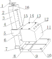
Fig. 1 is structural representation of the present invention.
Label in figure is: 1, runner; 2, limiting plate; 3, vertical guide rod; 4, graduation mark; 5, lifter plate; 6, data line interface; 7, base; 8, print needle; 9, dovetail groove; 10, pneumatic box; 11, pneumatic box; 12, control button; 13, upper end cover; 14, screw; 15, abrasive rubber cover; 16, vertical screw rod.
The specific embodiment
Below in conjunction with accompanying drawing, the present invention is further illustrated.
Embodiment
A kind of pneumatic marking machine as shown in Figure 1, comprise vertical guide rod 3, pneumatic box 10 and base 7, in described vertical guide rod 3, be provided with vertical screw rod 16, vertically screw rod 16 tops are connected with runner 1, the outside body of rod of described vertical guide rod 3 is connected with lifter plate 5, lifter plate 5 is threaded with vertical screw rod 16, form the elevating mechanism that lifter plate 5 moves up and down along vertical screw rod 16, described lifter plate 5 is also being provided with abrasive rubber cover 16 with vertical guide rod 3 junctions, described vertical guide rod 3 lower ends are connected with base 7, described lifter plate 5 is connected with pneumatic box 11, pneumatic box 11 is provided with control button 12 and data line interface 6, described pneumatic box 11 lower surfaces are also connected with print needle 8.
It also comprises limiting plate 2, and limiting plate 2 is positioned at the end face of vertical guide rod 3 towards pneumatic box 11 1 sides.
On described vertical guide rod 3, be also provided with graduation mark 4, graduation mark 4 is positioned at the end face of vertical guide rod 3 towards pneumatic box 11 1 sides.
Described pneumatic box 11 comprises upper end cover 13, and upper end cover 13 is flexibly connected with pneumatic box 11 by screw 14.
Described base 7 is provided with dovetail groove 9, and dovetail groove 9 is provided with two altogether, is each other criss-cross construction setting.
7 four corner locations of described base are also provided with tapped through hole 10.
Described base 7 bottoms scribble insulating barrier.
The present invention in use, marking machine is connected with external control computer by data line interface 6, pneumatic box 11 can move up and down along vertical guide rod 3, and print needle 8 can horizontal and vertically linearly move, and runner 1 is controlled the direction of rotation of vertical screw rod 16, and pneumatic box 11 lower surfaces are just to base 7, the thing to be identified that needs mark to know is put on base 7, input print What and task by computer, control power supply, source of the gas and the printing situation of marking machine by control button 12, get final product automatic marking; The present invention, except the heavier miscellaneous part of pneumatic box 11 weight is all lighter, only need to take the required floor space of base 7, and volume and weight has obtained right-sizing, and cost is practical.
Be as mentioned above embodiments of the invention.The present invention is not limited to above-mentioned embodiment, and anyone should learn the structural change of making under enlightenment of the present invention, and every have identical or close technical scheme with the present invention, within all falling into protection scope of the present invention.
Claims (7)
1. a pneumatic marking machine, it is characterized in that: comprise vertical guide rod (3), pneumatic box (10) and base (7), in described vertical guide rod (3), be provided with vertical screw rod (16), vertically screw rod (16) top is connected with runner (1), the outside body of rod of described vertical guide rod (3) is connected with lifter plate (5), lifter plate (5) is threaded with vertical screw rod (16), form the elevating mechanism that lifter plate (5) moves up and down along vertical screw rod (16), described lifter plate (5) is also being provided with abrasive rubber cover (15) with vertical guide rod (3) junction, described vertical guide rod (3) lower end is connected with base (7), described lifter plate (5) is connected with pneumatic box (11), pneumatic box (11) is provided with control button (12) and data line interface (6), described pneumatic box (11) lower surface is also connected with print needle (8).
2. a kind of pneumatic marking machine according to claim 1, is characterized in that: it also comprises limiting plate (2), and limiting plate (2) is positioned at the end face of vertical guide rod (3) towards pneumatic box (11) one sides.
3. a kind of pneumatic marking machine according to claim 1, is characterized in that: on described vertical guide rod (3), be also provided with graduation mark (4), graduation mark (4) is positioned at the end face of vertical guide rod (3) towards pneumatic box (11) one sides.
4. a kind of pneumatic marking machine according to claim 1, is characterized in that: described pneumatic box (11) comprises upper end cover (13), and upper end cover (13) is flexibly connected with pneumatic box (11) by screw (14).
5. a kind of pneumatic marking machine according to claim 1, is characterized in that: described base (7) is provided with dovetail groove (9), and dovetail groove (9) is provided with two altogether, is each other criss-cross construction setting.
6. a kind of pneumatic marking machine according to claim 1, is characterized in that: (7) four corner locations of described base are also provided with tapped through hole (10).
7. a kind of pneumatic marking machine according to claim 1, is characterized in that: described base (7) bottom scribbles insulating barrier.
Priority Applications (1)
| Application Number | Priority Date | Filing Date | Title |
|---|---|---|---|
| CN201310621946.5A CN103802485A (en) | 2013-05-09 | 2013-11-30 | Pneumatic marking machine |
Applications Claiming Priority (3)
| Application Number | Priority Date | Filing Date | Title |
|---|---|---|---|
| CN201310167442 | 2013-05-09 | ||
| CN201310167442.0 | 2013-05-09 | ||
| CN201310621946.5A CN103802485A (en) | 2013-05-09 | 2013-11-30 | Pneumatic marking machine |
Publications (1)
| Publication Number | Publication Date |
|---|---|
| CN103802485A true CN103802485A (en) | 2014-05-21 |
Family
ID=50535118
Family Applications (2)
| Application Number | Title | Priority Date | Filing Date |
|---|---|---|---|
| CN201310621946.5A Pending CN103802485A (en) | 2013-05-09 | 2013-11-30 | Pneumatic marking machine |
| CN201320769380.6U Expired - Fee Related CN203567365U (en) | 2013-05-09 | 2013-11-30 | Pneumatic marking machine convenient for handling |
Family Applications After (1)
| Application Number | Title | Priority Date | Filing Date |
|---|---|---|---|
| CN201320769380.6U Expired - Fee Related CN203567365U (en) | 2013-05-09 | 2013-11-30 | Pneumatic marking machine convenient for handling |
Country Status (1)
| Country | Link |
|---|---|
| CN (2) | CN103802485A (en) |
Cited By (2)
| Publication number | Priority date | Publication date | Assignee | Title |
|---|---|---|---|---|
| CN105538921A (en) * | 2016-01-18 | 2016-05-04 | 武汉法利普纳泽切割系统有限公司 | Adjusting device for marking machine and steel needle marking machine |
| CN106183473A (en) * | 2016-06-25 | 2016-12-07 | 浦江华德工艺品有限公司 | A kind of crystal marking machine |
Families Citing this family (3)
| Publication number | Priority date | Publication date | Assignee | Title |
|---|---|---|---|---|
| CN103802485A (en) * | 2013-05-09 | 2014-05-21 | 成都众山科技有限公司 | Pneumatic marking machine |
| CN106183474A (en) * | 2016-07-30 | 2016-12-07 | 安徽天斯努信息技术股份有限公司 | A kind of curved discs raises formula printer loading frame |
| CN106739560B (en) * | 2016-11-30 | 2018-05-04 | 郑州新世纪数码科技股份有限公司 | Safe for operation and accurately trolley frame |
Citations (6)
| Publication number | Priority date | Publication date | Assignee | Title |
|---|---|---|---|---|
| JPS55123486A (en) * | 1979-03-16 | 1980-09-22 | Ricoh Co Ltd | Shift controller for printing mechanism |
| CN201151239Y (en) * | 2008-01-10 | 2008-11-19 | 张勤 | Pneumatic marking machine |
| CN201456577U (en) * | 2009-04-30 | 2010-05-12 | 管忠林 | Small-sized pneumatic marking machine |
| CN201456571U (en) * | 2009-04-28 | 2010-05-12 | 管忠林 | Pneumatic marking machine controlled by computer |
| CN202623524U (en) * | 2012-05-10 | 2012-12-26 | 济南吉利汽车有限公司 | Pneumatic marking machine workbench |
| CN203567365U (en) * | 2013-05-09 | 2014-04-30 | 成都众山科技有限公司 | Pneumatic marking machine convenient for handling |
-
2013
- 2013-11-30 CN CN201310621946.5A patent/CN103802485A/en active Pending
- 2013-11-30 CN CN201320769380.6U patent/CN203567365U/en not_active Expired - Fee Related
Patent Citations (6)
| Publication number | Priority date | Publication date | Assignee | Title |
|---|---|---|---|---|
| JPS55123486A (en) * | 1979-03-16 | 1980-09-22 | Ricoh Co Ltd | Shift controller for printing mechanism |
| CN201151239Y (en) * | 2008-01-10 | 2008-11-19 | 张勤 | Pneumatic marking machine |
| CN201456571U (en) * | 2009-04-28 | 2010-05-12 | 管忠林 | Pneumatic marking machine controlled by computer |
| CN201456577U (en) * | 2009-04-30 | 2010-05-12 | 管忠林 | Small-sized pneumatic marking machine |
| CN202623524U (en) * | 2012-05-10 | 2012-12-26 | 济南吉利汽车有限公司 | Pneumatic marking machine workbench |
| CN203567365U (en) * | 2013-05-09 | 2014-04-30 | 成都众山科技有限公司 | Pneumatic marking machine convenient for handling |
Cited By (3)
| Publication number | Priority date | Publication date | Assignee | Title |
|---|---|---|---|---|
| CN105538921A (en) * | 2016-01-18 | 2016-05-04 | 武汉法利普纳泽切割系统有限公司 | Adjusting device for marking machine and steel needle marking machine |
| CN105538921B (en) * | 2016-01-18 | 2017-08-18 | 武汉法利普纳泽切割系统有限公司 | Marking machine adjusting apparatus and draw point marking machine |
| CN106183473A (en) * | 2016-06-25 | 2016-12-07 | 浦江华德工艺品有限公司 | A kind of crystal marking machine |
Also Published As
| Publication number | Publication date |
|---|---|
| CN203567365U (en) | 2014-04-30 |
Similar Documents
| Publication | Publication Date | Title |
|---|---|---|
| CN203567365U (en) | Pneumatic marking machine convenient for handling | |
| CN105082743A (en) | Servo shuttle rubber head independent drop pad printing machine | |
| CN103722083B (en) | Punching die | |
| CN204935117U (en) | Numerical control machine slide rail locking device | |
| CN204771563U (en) | Automatic bore riveter system | |
| CN203567367U (en) | Pneumatic marking machine with great ventilation | |
| CN203804892U (en) | Pneumatic pressure-installing machine | |
| CN201636109U (en) | Liquid charging valve | |
| CN104139610A (en) | Pneumatic marking machine convenient to disassemble | |
| CN207359380U (en) | A kind of rock ore bed perforating device | |
| CN204052933U (en) | Main spindle box displacement of center of gravity change mechanical compensating mechanism | |
| CN202006391U (en) | Mechanical drilling machine | |
| CN203228506U (en) | Detachable pneumatic marking machine | |
| CN204398527U (en) | A kind of ink droplet deflection adjusting device of Double-nozzle sprayer ink jet numbering machine | |
| CN203189377U (en) | Tri-shaft air cylinder | |
| CN108687251A (en) | A kind of manipulator and punching press assembly line for punching press assembly line | |
| CN204434232U (en) | A kind of lifting linking member catch gear | |
| CN206362552U (en) | A kind of automobile gearbox testboard positioner | |
| CN203567364U (en) | Removable pneumatic box of marking machine | |
| CN206614297U (en) | A kind of automatic clamping device for panel beating | |
| CN206084903U (en) | Engine gudgeon pin installs frock | |
| CN203401825U (en) | Typewriting structure of numerical control hydraulic punching machine | |
| CN102179338A (en) | Angle adjusting mechanism for fuel injection device | |
| CN202965486U (en) | Environmentally friendly pad printing machine | |
| CN202123039U (en) | Numerical control intelligent adhesive dispensing equipment |
Legal Events
| Date | Code | Title | Description |
|---|---|---|---|
| C06 | Publication | ||
| PB01 | Publication | ||
| C10 | Entry into substantive examination | ||
| SE01 | Entry into force of request for substantive examination | ||
| C12 | Rejection of a patent application after its publication | ||
| RJ01 | Rejection of invention patent application after publication |
Application publication date: 20140521 |