CN103828107A - Electrolyte membrane-electrode structure with resin frame for fuel cells - Google Patents
Electrolyte membrane-electrode structure with resin frame for fuel cells Download PDFInfo
- Publication number
- CN103828107A CN103828107A CN201280046196.7A CN201280046196A CN103828107A CN 103828107 A CN103828107 A CN 103828107A CN 201280046196 A CN201280046196 A CN 201280046196A CN 103828107 A CN103828107 A CN 103828107A
- Authority
- CN
- China
- Prior art keywords
- electrolyte membrane
- resin frame
- peripheral end
- electrode
- outer peripheral
- Prior art date
- Legal status (The legal status is an assumption and is not a legal conclusion. Google has not performed a legal analysis and makes no representation as to the accuracy of the status listed.)
- Granted
Links
Images


Classifications
-
- H—ELECTRICITY
- H01—ELECTRIC ELEMENTS
- H01M—PROCESSES OR MEANS, e.g. BATTERIES, FOR THE DIRECT CONVERSION OF CHEMICAL ENERGY INTO ELECTRICAL ENERGY
- H01M8/00—Fuel cells; Manufacture thereof
- H01M8/02—Details
- H01M8/0271—Sealing or supporting means around electrodes, matrices or membranes
-
- H—ELECTRICITY
- H01—ELECTRIC ELEMENTS
- H01M—PROCESSES OR MEANS, e.g. BATTERIES, FOR THE DIRECT CONVERSION OF CHEMICAL ENERGY INTO ELECTRICAL ENERGY
- H01M8/00—Fuel cells; Manufacture thereof
- H01M8/10—Fuel cells with solid electrolytes
- H01M8/1004—Fuel cells with solid electrolytes characterised by membrane-electrode assemblies [MEA]
-
- H—ELECTRICITY
- H01—ELECTRIC ELEMENTS
- H01M—PROCESSES OR MEANS, e.g. BATTERIES, FOR THE DIRECT CONVERSION OF CHEMICAL ENERGY INTO ELECTRICAL ENERGY
- H01M8/00—Fuel cells; Manufacture thereof
- H01M8/02—Details
- H01M8/0202—Collectors; Separators, e.g. bipolar separators; Interconnectors
- H01M8/0267—Collectors; Separators, e.g. bipolar separators; Interconnectors having heating or cooling means, e.g. heaters or coolant flow channels
-
- H—ELECTRICITY
- H01—ELECTRIC ELEMENTS
- H01M—PROCESSES OR MEANS, e.g. BATTERIES, FOR THE DIRECT CONVERSION OF CHEMICAL ENERGY INTO ELECTRICAL ENERGY
- H01M8/00—Fuel cells; Manufacture thereof
- H01M8/02—Details
- H01M8/0271—Sealing or supporting means around electrodes, matrices or membranes
- H01M8/0273—Sealing or supporting means around electrodes, matrices or membranes with sealing or supporting means in the form of a frame
-
- H—ELECTRICITY
- H01—ELECTRIC ELEMENTS
- H01M—PROCESSES OR MEANS, e.g. BATTERIES, FOR THE DIRECT CONVERSION OF CHEMICAL ENERGY INTO ELECTRICAL ENERGY
- H01M8/00—Fuel cells; Manufacture thereof
- H01M8/02—Details
- H01M8/0271—Sealing or supporting means around electrodes, matrices or membranes
- H01M8/0276—Sealing means characterised by their form
-
- H—ELECTRICITY
- H01—ELECTRIC ELEMENTS
- H01M—PROCESSES OR MEANS, e.g. BATTERIES, FOR THE DIRECT CONVERSION OF CHEMICAL ENERGY INTO ELECTRICAL ENERGY
- H01M8/00—Fuel cells; Manufacture thereof
- H01M8/02—Details
- H01M8/0271—Sealing or supporting means around electrodes, matrices or membranes
- H01M8/0286—Processes for forming seals
-
- H—ELECTRICITY
- H01—ELECTRIC ELEMENTS
- H01M—PROCESSES OR MEANS, e.g. BATTERIES, FOR THE DIRECT CONVERSION OF CHEMICAL ENERGY INTO ELECTRICAL ENERGY
- H01M8/00—Fuel cells; Manufacture thereof
- H01M8/10—Fuel cells with solid electrolytes
- H01M2008/1095—Fuel cells with polymeric electrolytes
-
- H—ELECTRICITY
- H01—ELECTRIC ELEMENTS
- H01M—PROCESSES OR MEANS, e.g. BATTERIES, FOR THE DIRECT CONVERSION OF CHEMICAL ENERGY INTO ELECTRICAL ENERGY
- H01M8/00—Fuel cells; Manufacture thereof
- H01M8/02—Details
- H01M8/0271—Sealing or supporting means around electrodes, matrices or membranes
- H01M8/028—Sealing means characterised by their material
- H01M8/0284—Organic resins; Organic polymers
-
- Y—GENERAL TAGGING OF NEW TECHNOLOGICAL DEVELOPMENTS; GENERAL TAGGING OF CROSS-SECTIONAL TECHNOLOGIES SPANNING OVER SEVERAL SECTIONS OF THE IPC; TECHNICAL SUBJECTS COVERED BY FORMER USPC CROSS-REFERENCE ART COLLECTIONS [XRACs] AND DIGESTS
- Y02—TECHNOLOGIES OR APPLICATIONS FOR MITIGATION OR ADAPTATION AGAINST CLIMATE CHANGE
- Y02E—REDUCTION OF GREENHOUSE GAS [GHG] EMISSIONS, RELATED TO ENERGY GENERATION, TRANSMISSION OR DISTRIBUTION
- Y02E60/00—Enabling technologies; Technologies with a potential or indirect contribution to GHG emissions mitigation
- Y02E60/30—Hydrogen technology
- Y02E60/50—Fuel cells
Landscapes
- Life Sciences & Earth Sciences (AREA)
- Engineering & Computer Science (AREA)
- Manufacturing & Machinery (AREA)
- Sustainable Development (AREA)
- Sustainable Energy (AREA)
- Chemical & Material Sciences (AREA)
- Chemical Kinetics & Catalysis (AREA)
- Electrochemistry (AREA)
- General Chemical & Material Sciences (AREA)
- Fuel Cell (AREA)
Abstract
Description
技术领域 technical field
本发明涉及一种燃料电池用带有树脂框的电解质膜电极构造体,其具备:将分别具有电极催化剂层和气体扩散层的第一电极以及第二电极设置于固体高分子电解质膜的两侧,并且所述第一电极的外形尺寸设定得比所述第二电极的外形尺寸小的电解质膜电极构造体;以及绕所述固体高分子电解质膜的外周一周而设置的树脂制框部件。 The present invention relates to an electrolyte membrane electrode structure with a resin frame for a fuel cell, comprising: a first electrode and a second electrode each having an electrode catalyst layer and a gas diffusion layer are provided on both sides of a solid polymer electrolyte membrane , and an electrolyte membrane electrode structure in which the external dimensions of the first electrode are set to be smaller than those of the second electrode; and a resin frame member provided around the outer circumference of the solid polymer electrolyte membrane. the
背景技术 Background technique
一般而言,固体高分子型燃料电池采用由高分子离子交换膜构成的固体高分子电解质膜。该燃料电池在固体高分子电解质膜的两侧分别配置有由催化剂层(电极催化剂层)和气体扩散层(多孔质碳)构成的阳极侧电极以及阴极侧电极,从而形成电解质膜电极构造体(MEA),并利用隔板(双极性板)夹持该电解质膜电极构造体(MEA)。通过层叠规定数量的该燃料电池,例如用作车载用燃料电池堆。 In general, a solid polymer fuel cell employs a solid polymer electrolyte membrane composed of a polymer ion exchange membrane. In this fuel cell, an anode-side electrode and a cathode-side electrode composed of a catalyst layer (electrode catalyst layer) and a gas diffusion layer (porous carbon) are respectively disposed on both sides of a solid polymer electrolyte membrane to form an electrolyte membrane electrode structure ( MEA), and the electrolyte membrane electrode assembly (MEA) is sandwiched by separators (bipolar plates). By stacking a predetermined number of these fuel cells, it can be used, for example, as a vehicle-mounted fuel cell stack. the
在这种电解质膜电极构造体中,一方的气体扩散层被设定成比固体高分子电解质膜小的表面积,并且,另一方的气体扩散层被设定成与所述固体高分子电解质膜相同的表面积,即存在构成所谓的台阶型MEA的情况。 In such an electrolyte membrane electrode structure, one gas diffusion layer is set to have a smaller surface area than the solid polymer electrolyte membrane, and the other gas diffusion layer is set to have the same surface area as the solid polymer electrolyte membrane. The surface area, that is, there is a situation that constitutes a so-called step-type MEA. the
通常,在燃料电池堆中,层叠有大量的电解质膜电极构造体,为了抑制成本,希望所述电解质膜电极构造体廉价地构成。因此,尤其为了削减高价的固体高分子电解质膜的使用量,并实现结构的简化,提出有各种方案。 In general, a large number of electrolyte membrane electrode structures are stacked in a fuel cell stack, and it is desired that the electrolyte membrane electrode structures be constructed at low cost in order to suppress costs. Therefore, various proposals have been made in order to reduce the amount of expensive solid polymer electrolyte membrane used and to simplify the structure. the
例如,在日本特开2007-66766号公报所公开的电解质膜一电极接合体中,如图18所示,具备:电解质膜1、在所述电解质膜1的一方侧配置的阴极催化剂层2a、在所述电解质膜1的另一方侧配置的阳极催化剂层 2b、以及在所述电解质膜1的两侧配置的气体扩散层3a、3b。
For example, in the electrolyte membrane-electrode assembly disclosed in Japanese Patent Application Laid-Open No. 2007-66766, as shown in FIG. The
阳极侧的气体扩散层3b构成为面积与电解质膜1的面积相同、且比阴极侧的气体扩散层3a的面积大。在该电解质膜电极接合体(MEA)的边缘区域配置有衬垫构造体4。气体扩散层3a侧的电解质膜1的外周部与衬垫构造体4经粘接层5接合。
The
但是,在上述的日本特开2007-66766号公报中,MEA和衬垫构造体4仅仅是通过粘接层5而固定于从气体扩散层3a露出到外部的电解质膜1的外周缘部。因此,MEA与衬垫构造体4的接合强度低,存在无法得到希望的强度的问题。
However, in the above-mentioned Japanese Patent Application Laid-Open No. 2007-66766, the MEA and the
而且,使气体扩散层3a、3b的外周端部与衬垫构造体4的内周端部相互气密地密接,在制造上是相当困难的。因此,存在着在气体扩散层3a、3b的外周端部与衬垫构造体4的内周端部之间容易产生间隙,气体密封性降低,燃料气体与氧化剂气体混合的问题。
Furthermore, it is quite difficult in terms of manufacture to make the outer peripheral end portions of the
发明内容 Contents of the invention
本发明用于解决这种问题,其目的在于,提供一种燃料电池用带有树脂框的电解质膜电极构造体,绕固体高分子电解质膜的外周一周而牢固且容易接合树脂制框部件,并且能够可靠地维持希望的气体密封性。 The present invention is to solve such a problem, and its object is to provide an electrolyte membrane electrode structure with a resin frame for a fuel cell, which is firmly and easily bonded to a resin frame member around the outer circumference of a solid polymer electrolyte membrane, and Desired gas-tightness can be reliably maintained. the
本发明涉及一种燃料电池用带有树脂框的电解质膜电极构造体,其具备:电解质膜电极构造体,其将分别具有电极催化剂层与气体扩散层的第一电极以及第二电极配置在固体高分子电解质膜的两侧,并且所述第一电极的外形尺寸设定得比所述第二电极的外形尺寸小;以及树脂制框部件,其围绕所述固体高分子电解质膜的外周而设置。 The present invention relates to an electrolyte membrane electrode structure with a resin frame for a fuel cell, comprising: an electrolyte membrane electrode structure in which a first electrode and a second electrode each having an electrode catalyst layer and a gas diffusion layer are disposed both sides of the polymer electrolyte membrane, and the external dimensions of the first electrode are set to be smaller than the external dimensions of the second electrode; and a resin frame member provided around the outer periphery of the solid polymer electrolyte membrane . the
在该燃料电池用带有树脂框的电解质膜电极构造体中,具备中间层,该中间层连续配置在如下三处,其一是在第一电极的外周端部与树脂制框部件的内周端部之间,其二在从所述第一电极的所述外周端部露出到外部的固体高分子电解质膜的外周缘部,其三在第二电极的外周端部与所述树脂制框部件的内周端部之间。 In this electrolyte membrane electrode structure with a resin frame for a fuel cell, an intermediate layer is provided, and the intermediate layer is continuously arranged at the following three places, one of which is between the outer peripheral end of the first electrode and the inner periphery of the resin frame member. Between the ends, two of them are at the outer peripheral edge of the solid polymer electrolyte membrane exposed from the outer peripheral end of the first electrode, and the third are at the outer peripheral end of the second electrode and the resin frame. between the inner peripheral ends of the component. the
另外,在该燃料电池用带有树脂框的电解质膜电极构造体中,中间层优选由不同于树脂制框部件的树脂材料构成。 In addition, in the fuel cell electrolyte membrane electrode assembly with a resin frame, the intermediate layer is preferably composed of a resin material different from the resin frame member. the
进而,在该燃料电池用带有树脂框的电解质膜电极构造体中,优选在至少一方的气体扩散层的外周端缘部,设有含浸与中间层相同的成分的含浸层。 Furthermore, in the fuel cell electrolyte membrane electrode assembly with a resin frame, it is preferable that an impregnated layer impregnated with the same composition as the intermediate layer is provided on the outer peripheral edge portion of at least one gas diffusion layer. the
进而另外,在该燃料电池用带有树脂框的电解质膜电极构造体中,含浸层优选以85%以上的空孔填充率含浸于气体扩散层。 Further, in the electrolyte membrane electrode assembly with a resin frame for a fuel cell, the impregnated layer is preferably impregnated into the gas diffusion layer with a pore filling rate of 85% or more. the
另外,在该燃料电池用带有树脂框的电解质膜电极构造体中,优选在中间层的一方的端部与第一电极的外周端部以及树脂制框部件的内周端部之间,形成有第一间隙,并且在所述中间层的另一方的端部与第二电极的外周端部以及所述树脂制框部件的内周端部之间,形成有第二间隙,在所述第一间隙,将一体或分体设于所述树脂制框部件的第一突起部熔融而形成第一树脂含浸部,另一方面,在所述第二间隙,将一体或分体设于所述树脂制框部件的第二突起部熔融而形成第二树脂含浸部。 In addition, in the electrolyte membrane electrode assembly with a resin frame for a fuel cell, it is preferable that between one end of the intermediate layer and the outer peripheral end of the first electrode and the inner peripheral end of the resin frame member, a There is a first gap, and a second gap is formed between the other end of the intermediate layer and the outer peripheral end of the second electrode and the inner peripheral end of the resin frame member. In a gap, the first protrusion part integrally or separately provided on the resin frame member is melted to form a first resin impregnated part. On the other hand, in the second gap, the integral or separate part provided on the The second protrusion portion of the resin frame member is melted to form a second resin impregnated portion. the
根据本发明,除了从第一电极的外周端部露出到外部的固体高分子电解质膜的外周缘部以外,在所述第一电极的外周端部以及第二电极的外周端部与树脂制框部件的内周端部之间连续设有中间层。 According to the present invention, in addition to the outer peripheral edge of the solid polymer electrolyte membrane exposed from the outer peripheral end of the first electrode, the outer peripheral end of the first electrode and the outer peripheral end of the second electrode are connected to the resin frame. An intermediate layer is continuously provided between the inner peripheral ends of the components. the
因此,第一电极以及第二电极与树脂制框部件的接合强度与粘接的接合相比得到良好提高,能够尽量抑制剥落等的产生。而且,在第一电极的外周端部与树脂制框部件的内周端部之间、以及在第二电极的外周端部与所述树脂制框部件的内周端部之间,未形成间隙。因此,能够可靠地维持希望的气体密封性,能够以简单且经济性的结构,尽量抑制燃料气体与氧化剂气体的混合。 Therefore, the bonding strength between the first electrode and the second electrode and the resin frame member is better than that of bonding, and the occurrence of peeling and the like can be suppressed as much as possible. Furthermore, no gap is formed between the outer peripheral end of the first electrode and the inner peripheral end of the resin frame member, and between the outer peripheral end of the second electrode and the inner peripheral end of the resin frame member. . Therefore, desired gas-tightness can be reliably maintained, and mixing of fuel gas and oxidant gas can be suppressed as much as possible with a simple and economical structure. the
附图说明 Description of drawings
图1是组装有本发明的第一实施方式的带有树脂框的电解质膜电极构造体的固体高分子型燃料电池的主要部分分解立体说明图。 FIG. 1 is an exploded perspective view illustrating main parts of a solid polymer fuel cell incorporating an electrolyte membrane electrode assembly with a resin frame according to a first embodiment of the present invention. the
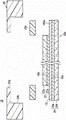
图2是所述燃料电池的图1中的II-II线剖面说明图。 Fig. 2 is an explanatory view of a section taken along line II-II in Fig. 1 of the fuel cell. the
图3是所述带有树脂框的电解质膜电极构造体的阴极侧电极侧的正面说明图。 3 is an explanatory front view of the cathode-side electrode side of the electrolyte membrane electrode structure with a resin frame. the
图4是所述带有树脂框的电解质膜电极构造体的阳极侧电极侧的正面说明图。 4 is an explanatory front view of the anode-side electrode side of the electrolyte membrane electrode structure with a resin frame. the
图5是制造所述带有树脂框的电解质膜电极构造体的方法的说明图。 FIG. 5 is an explanatory diagram of a method of manufacturing the electrolyte membrane electrode assembly with a resin frame. the
图6是制造所述带有树脂框的电解质膜电极构造体的方法的说明图。 FIG. 6 is an explanatory diagram of a method of manufacturing the electrolyte membrane electrode assembly with a resin frame. the
图7是制造所述带有树脂框的电解质膜电极构造体的方法的说明图。 FIG. 7 is an explanatory diagram of a method of manufacturing the electrolyte membrane electrode assembly with a resin frame. the
图8是空孔填充率与气体流量的关系说明图。 Fig. 8 is an explanatory diagram of the relationship between the pore filling rate and the gas flow rate. the
图9是制造所述带有树脂框的电解质膜电极构造体的其他方法的说明图。 FIG. 9 is an explanatory diagram of another method of manufacturing the electrolyte membrane electrode assembly with a resin frame. the
图10是制造所述带有树脂框的电解质膜电极构造体的其他方法的说明图。 FIG. 10 is an explanatory diagram of another method of manufacturing the electrolyte membrane electrode assembly with a resin frame. the
图11是组装有本发明的第二实施方式的带有树脂框的电解质膜电极构造体的固体高分子型燃料电池的主要部分分解立体说明图。 FIG. 11 is an exploded perspective view illustrating main parts of a polymer electrolyte fuel cell incorporating an electrolyte membrane electrode assembly with a resin frame according to a second embodiment of the present invention. the
图12是组装有本发明的第三实施方式的带有树脂框的电解质膜电极构造体的固体高分子型燃料电池的剖面说明图。 12 is a cross-sectional explanatory view of a polymer electrolyte fuel cell incorporating an electrolyte membrane electrode assembly with a resin frame according to a third embodiment of the present invention. the
图13是组装有本发明的第四实施方式的带有树脂框的电解质膜电极构造体的固体高分子型燃料电池的剖面说明图。 13 is a cross-sectional explanatory view of a polymer electrolyte fuel cell incorporating an electrolyte membrane electrode assembly with a resin frame according to a fourth embodiment of the present invention. the
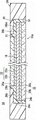
图14是组装有本发明的第五实施方式的带有树脂框的电解质膜电极构造体的固体高分子型燃料电池的剖面说明图。 14 is a cross-sectional explanatory view of a polymer electrolyte fuel cell incorporating an electrolyte membrane electrode assembly with a resin frame according to a fifth embodiment of the present invention. the
图15是制造所述带有树脂框的电解质膜电极构造体的方法的说明图。 Fig. 15 is an explanatory diagram of a method of manufacturing the electrolyte membrane electrode assembly with a resin frame. the
图16是制造所述带有树脂框的电解质膜电极构造体的方法的说明图。 FIG. 16 is an explanatory diagram of a method of manufacturing the electrolyte membrane electrode assembly with a resin frame. the
图17是制造所述带有树脂框的电解质膜电极构造体的方法的说明图。 Fig. 17 is an explanatory diagram of a method of manufacturing the electrolyte membrane electrode assembly with a resin frame. the
图18是日本特开2007-66766号公报所公开的电解质膜一电极接合体的说明图。 Fig. 18 is an explanatory diagram of an electrolyte membrane-electrode assembly disclosed in JP-A-2007-66766. the
具体实施方式 Detailed ways
如图1以及图2所示,组装有本发明的第一实施方式的带有树脂框的 电解质膜电极构造体10的固体高分子型燃料电池12利用第一隔板14以及第二隔板16夹持所述带有树脂框的电解质膜电极构造体10。第一隔板14以及第二隔板16例如由钢板、不锈钢板、铝板、镀敷处理钢板或者对其金属表面实施了防腐蚀用的表面处理的金属板、碳部件等构成。
As shown in FIGS. 1 and 2, a solid
如图2所示,带有树脂框的电解质膜电极构造体10具备电解质膜电极构造体10a,并且所述电解质膜电极构造体10a例如具有:在全氟磺酸的薄膜中含浸有水的固体高分子电解质膜18;以及夹持所述固体高分子电解质膜18的阳极侧电极(第二电极)20以及阴极侧电极(第一电极)22。固体高分子电解质膜18除了氟系电解质以外,还使用HC(碳化氢)系电解质。
As shown in FIG. 2 , the electrolyte
阴极侧电极22具有比固体高分子电解质膜18以及阳极侧电极20小的表面积。另外,阴极侧电极22也可以具有比阳极侧电极20大的表面积。固体高分子电解质膜18的外周缘部相比小的一方的电极例如阴极侧电极22的外周突出即可,也可以不配置于与大的一方的电极例如阳极侧电极20的端部相同的位置。
The cathode-
阳极侧电极20配置于固体高分子电解质膜18的一方的面18a。阴极侧电极22配置于固体高分子电解质膜18的另一方的面18b,并且使所述固体高分子电解质膜18的外周端部18be呈画框状露出。
The anode-
阳极侧电极20设有:与固体高分子电解质膜18的面18a接合的电极催化剂层20a;层叠于所述电极催化剂层20a的气体扩散层20b。阴极侧电极22设有:与固体高分子电解质膜18的面18b接合的电极催化剂层22a;以及层叠于所述电极催化剂层22a的气体扩散层22b。
The anode-
形成在碳黑承载白金粒子的催化剂粒子,使用高分子电解质作为离子导传性粘接剂,在该高分子电解质的溶液中均匀混合所述催化剂粒子,制作催化剂膏,将该催化剂膏印刷、涂布或转印于固体高分子电解质膜18的两面,由此构成电极催化剂层20a、22a。气体扩散层20b、22b由碳纸等构成,并且所述气体扩散层20b的平面尺寸设定为大于所述气体扩散层22b的平面尺寸。
Catalyst particles are formed on carbon black carrying platinum particles, and a polymer electrolyte is used as an ion-conducting adhesive, and the catalyst particles are uniformly mixed in a solution of the polymer electrolyte to prepare a catalyst paste, which is printed and coated. cloth or transfer printing on both surfaces of the solid
如图2~图4所示,带有树脂框的电解质膜电极构造体10具备树脂制框部件24,该树脂制框部件24围绕固体高分子电解质膜18的外周,并且与阴极侧电极22以及阳极侧电极20接合。树脂制框部件24除了例如由PPS(聚苯硫醚)或PPA(聚邻苯二甲酰胺)等构成以外,也可以使用具有弹性的高分子材料。
As shown in FIGS. 2 to 4 , the electrolyte
树脂制框部件24具有:内部设有带台阶开口部、且配置在内侧的第一内周端部24a;以及相比所述第一内周端部24a配置在外侧的第二内周端部24b。在树脂制框部件24与电解质膜电极构造体10a之间设有中间层26。
The
中间层26连续地一体具有第一板状部26a、第二板状部26b以及第三板状部26c,第一板状部26a配置在构成阴极侧电极22的气体扩散层22b的外周端部22be与树脂制框部件24的第一内周端部24a之间,第二板状部26b配置在从所述外周端部22be露出到外部的固体高分子电解质膜18的外周端部18be,第三板状部26c配置在构成阳极侧电极20的气体扩散层20b的外周端部20be与所述树脂制框部件24的第二内周端部24b之间。
The
中间层26剖面具有大致Z形状,是由不同于树脂制框部件24的树脂材料构成的。具体地说,中间层26使用硅系橡胶(合成橡胶)、氟橡胶(合成橡胶)、环氧系树脂(合成橡胶)、聚氨酯系树脂(合成橡胶)、变性PET(聚对苯二甲酸乙二醇酯)树脂(合成橡胶)、PVDF(聚偏氟乙烯)树脂(合成橡胶)或烯烃系树脂(合成橡胶),或者使用热熔等。
The cross section of the
在构成阴极侧电极22的气体扩散层22b的外周缘部设有第一含浸层28a,该第一含浸层28a从外周端位置到内侧以具有既定范围的方式含浸与中间层26相同的成分。在构成阳极侧电极20的气体扩散层20b的外周缘部设有第二含浸层28b,该第二含浸层28b从外周端位置到内侧以具有既定范围的方式含浸与中间层26相同的成分。第一含浸层28a以及第二含浸层28b分别以85%以上的空孔填充率含浸于气体扩散层22b以及气体扩散层20b。
The first impregnated
如图3所示,第一含浸层28a遍及构成阴极侧电极22的气体扩散层22b的全周而形成。如图4所示,第二含浸层28b遍及构成阳极侧电极20的气体扩散层20b的全周而形成。
As shown in FIG. 3 , the first impregnated
如图1所示,在燃料电池12的箭头B方向(图1中的水平方向)的一端缘部,以在层叠方向即箭头A方向上相互连通的方式,沿箭头C方向(铅直方向)配列设有:用于供给氧化剂气体例如含氧气体的氧化剂气体入口连通孔30a;用于供给冷却介质的冷却介质入口连通孔32a;以及用于排出燃料气体例如含氢气体的燃料气体出口连通孔34b。
As shown in FIG. 1 , at one end edge portion of the
在燃料电池12的箭头B方向的另一端缘部,以在箭头A方向上相互连通的方式,沿箭头C方向配列设有:用于供给燃料气体的燃料气体入口连通孔34a;用于排出冷却介质的冷却介质出口连通孔32b;以及用于排出氧化剂气体的氧化剂气体出口连通孔30b。
On the other edge portion of the
在第二隔板16的面向带有树脂框的电解质膜电极构造体10的面16a上,设有与氧化剂气体入口连通孔30a和氧化剂气体出口连通孔30b连通的氧化剂气体流路36。
On the
在第一隔板14的面向带有树脂框的电解质膜电极构造体10的面14a上,形成有与燃料气体入口连通孔34a和燃料气体出口连通孔34b连通的燃料气体流路38。在第一隔板14的面14b与第二隔板16的面16b之间,形成有与冷却介质入口连通孔32a和冷却介质出口连通孔32b连通的冷却介质流路40。
On the
如图1以及图2所示,在第一隔板14的面14a、14b上,围绕该第一隔板14的外周端部而一体形成第一密封部件42,并且在第二隔板16的面16a、16b上,围绕该第二隔板16的外周端部而一体形成第二密封部件44。
As shown in FIGS. 1 and 2 , on the
如图2所示,第一密封部件42具有:抵接于带有树脂框的电解质膜电极构造体10的树脂制框部件24上的第一凸状密封部42a;以及抵接于第二隔板16的第二密封部件44上的第二凸状密封部42b。第二密封部件44构成平面密封件。需要说明的是,也可以取代第二凸状密封部42b, 在第二密封部件44上设置凸状密封部(未图示)。
As shown in FIG. 2 , the first sealing
第一以及第二密封部件42、44例如采用EPDM、NBR、氟橡胶、硅酮橡胶、氟硅橡胶、丁基橡胶、天然橡胶、苯乙烯橡胶、氯丁二烯或丙烯酸橡胶等密封材料,缓冲材料或者填料材料等具有弹性的密封部件。
The first and
如图1所示,在第一隔板14上形成有:将燃料气体入口连通孔34a连通于燃料气体流路38的供给孔部46;以及将所述燃料气体流路38连通于燃料气体出口连通孔34b的排出孔部48。
As shown in FIG. 1 , the
下面,对制造带有树脂框的电解质膜电极构造体10的方法进行以下说明。
Next, a method of manufacturing the electrolyte
首先,如图5所示,制作作为台阶MFA的电解质膜电极构造体10a。具体地说,在固体高分子电解质膜18的两方的面18a、18b上涂布电极催化剂层20a、22a。然后,在固体高分子电解质膜18的面18a侧,即在电极催化剂层20a上配置气体扩散层20b,并且在所述固体高分子电解质膜18的面18b,即在电极催化剂层22a上配置气体扩散层22b。将它们一体层叠并实施热冲压处理,由此制作电解质膜电极构造体10a。
First, as shown in FIG. 5 , an electrolyte
另一方面,树脂制框部件24预先由注射成形机(未图示)成形,使所述树脂制框部件24和电解质膜电极构造体10a的位置对合。树脂制框部件24具有第一内周端部24a和第二内周端部24b。在电解质膜电极构造体10a中,固体高分子电解质膜18的外周端部18be呈画框状露出,对应于所述外周端部18be配置构成中间层26的第二板状部26b。
On the other hand, the
然后,如图6所示,树脂制框部件24和电解质膜电极构造体10a是通过在第一内周端部24a配置阴极侧电极22、并在第二内周端部24b配置固体高分子电解质膜18以及阳极侧电极20而隔着第二板状部26b形成一体。在此,在第一内周端部24a与构成阴极侧电极22的气体扩散层22b的外周端部22be之间、以及在第二内周端部24b与构成阳极侧电极20的气体扩散层20b的外周端部20be之间,分别设有间隙S1以及S2。
Then, as shown in FIG. 6, the
接着,如图7所示,向各间隙S1、S2注射与第二板状部26b相同的中间层26的材料。因此,通过填充于间隙S1、S2的材料硬化,从而 形成第一板状部26a以及第三板状部26c,它们与第二板状部26b一体化而形成中间层26。需要说明的是,第一板状部26a、第二板状部26b以及第三板状部26c只要密接性好,各自的材料组成也可以不同。
Next, as shown in FIG. 7 , the same material for the
进而,注射的材料被含浸于气体扩散层22b、20b。因此,在气体扩散层22b的外周缘部,从外周端位置向内侧以具有既定范围的方式设有第一含浸层28a。另一方面,在气体扩散层20b的外周缘部,从外周端位置向内侧以具有既定范围的方式设有第二含浸层28b。
Furthermore, the injected material is impregnated into the gas diffusion layers 22b, 20b. Therefore, the first impregnated
此时,第一含浸层28a以及第二含浸层28b各自以85%以上的空孔填充率被含浸于气体扩散层22b以及气体扩散层20b。空孔填充率与气体扩散层流量作为例如基于细孔分布测定器的评价结果具有图8所示的关系。由此,若空孔填充率是85%以上,则能够可靠地密封气体。
At this time, the first impregnated
此时,在第一实施方式中,在树脂制框部件24与电解质膜电极构造体10a之间设有中间层26。中间层26连续地一体具有第一板状部26a、第二板状部26b、以及第三板状部26c,第一板状部26a无间隙地配置在构成阴极侧电极22的气体扩散层22b的外周端部22b e与树脂制框部件24的第一内周端部24a之间,第二板状部26b配置于从所述外周端部22be露出到外部的固体高分子电解质膜18的外周端部18be,第三板状部26c无间隙地配置在构成阳极侧电极20的气体扩散层20b的外周端部20be与所述树脂制框部件24的第二内周端部24b之间。
At this time, in the first embodiment, the
此外,在气体扩散层22b以及气体扩散层20b设有第一含浸层28a以及第二含浸层28b。需要说明的是,还可以仅设置第一含浸层28a,或仅设置第二含浸层28b。
In addition, a first impregnated
因此,阴极侧电极22以及阳极侧电极20与树脂制框部件24的接合强度与粘接接合相比有良好的提高,能够尽量抑制剥落等的产生。
Therefore, the bonding strength between the cathode-
而且,在第一内周端部24a与构成阴极侧电极22的气体扩散层22b的外周端部22be之间、以及在第二内周端部24b与构成阳极侧电极20的气体扩散层20b的外周端部20be之间未形成间隙。因此可得到如下效果:能够可靠地维持希望的气体密封性,能够以简单且经济性的结构尽 量抑制燃料气体与氧化剂气体的混合。
Furthermore, between the first inner
以下说明如此构成的燃料电池12的动作。
The operation of the
首先,如图1所示,向氧化剂气体入口连通孔30a供给含氧气体等氧化剂气体,并且向燃料气体入口连通孔34a供给含氢气体等燃料气体。进而,向冷却介质入口连通孔32a供给纯水或乙撑二醇、油等冷却介质。
First, as shown in FIG. 1 , an oxidizing gas such as an oxygen-containing gas is supplied to the oxidizing gas
因此,氧化剂气体从氧化剂气体入口连通孔30a被导入第二隔板16的氧化剂气体流路36,并沿箭头B方向移动而供给向电解质膜电极构造体10a的阴极侧电极22。另一方面,燃料气体从燃料气体入口连通孔34a通过供给孔部46而被导入第一隔板14的燃料气体流路38。燃料气体沿着燃料气体流路38在箭头B方向上移动,被供给向电解质膜电极构造体10a的阳极侧电极20。
Therefore, the oxidizing gas is introduced into the oxidizing
因此,在各电解质膜电极构造体10a中,供给向阴极侧电极22的氧化剂气体与供给向阳极侧电极20的燃料气体在电极催化剂层内通过电化学反应而被消耗,从而进行发电。
Therefore, in each electrolyte
接着,供给向阴极侧电极22而被消耗了的氧化剂气体沿着氧化剂气体出口连通孔30b在箭头A方向上被排出。同样,供给向阳极侧电极20而被消耗了的燃料气体通过排出孔部48而沿着燃料气体出口连通孔34b在箭头A方向上被排出。
Next, the oxidizing gas supplied to the cathode-
另外,供给向冷却介质入口连通孔32a的冷却介质在被导入第一隔板14与第二隔板16之间的冷却介质流路40之后,沿箭头B方向流通。该冷却介质在冷却了电解质膜电极构造体10a之后,从冷却介质出口连通孔32b被排出。
In addition, the cooling medium supplied to the cooling medium
接着,以下说明制造带有树脂框的电解质膜电极构造体10的其他方法。
Next, another method of manufacturing the electrolyte
首先,如图9所示,在与上述同样制作了电解质膜电极构造体10a之后,在所述电解质膜电极构造体10a的外周,将材料与中间层26相同的液状密封件LS一体化。液状密封件LS被设置成对构成阴极侧电极22的气体扩散层22b的外周端部22be、固体高分子电解质膜18的外周端 部18be以及构成阳极侧电极20的气体扩散层20b的外周端部20be进行覆盖,并且一体形成第一含浸层28a以及第二含浸层28b。
First, as shown in FIG. 9 , after the electrolyte
因此,在液状密封件LS半硬化后,如图10所示,在电解质膜电极构造体10a一体形成树脂制框部件24。因此,半硬化了的液状密封件LS向形成于电解质膜电极构造体10a与树脂制框部件24之间的间隙S1、S2流动而硬化。因此,通过除去向树脂制框部件24的外侧延伸的飞边(未图示),可得到带有树脂框的电解质膜电极构造体10。
Therefore, after the liquid seal LS is semi-cured, as shown in FIG. 10 , the
图11是组装有本发明的第二实施方式的带有树脂框的电解质膜电极构造体60的固体高分子型燃料电池62的主要部分分解立体说明图。
FIG. 11 is an exploded perspective view illustrating main parts of a polymer
需要说明的是,对于与组装有第一实施方式的带有树脂框的电解质膜电极构造体10的燃料电池12相同的构成要素,标注同一参照符号,省略其详细说明。另外,在以下说明的第三以后的实施方式中也同样,省略其详细说明。
Note that the same reference numerals are attached to the same components as those of the
带有树脂框的电解质膜电极构造体60具备电解质膜电极构造体10a,并且设有围绕固体高分子电解质膜18的外周且与阴极侧电极22以及阳极侧电极20接合的树脂制框部件64。树脂制框部件64被设定成与第一隔板14以及第二隔板16相同的外形尺寸,在外周缘部形成有氧化剂气体入口连通孔30a、冷却介质入口连通孔32a、燃料气体出口连通孔34b、燃料气体入口连通孔34a、冷却介质出口连通孔32b以及氧化剂气体出口连通孔30b。
The electrolyte
在如此构成的第二实施方式中,在树脂制框部件64与电解质膜电极构造体10a之间设有中间层26,并且在气体扩散层22b以及气体扩散层20b设有第一含浸层28a以及第二含浸层28b。
In the second embodiment thus constituted, the
因此,阴极侧电极22以及阳极侧电极20与树脂制框部件64的接合强度与粘接接合相比有良好的提高,能够尽量抑制剥落等的产生。而且,可以得到与上述的第一实施方式同样的下述效果等:能够以简单且经济性的结构,尽量抑制燃料气体与氧化剂气体的混合。
Therefore, the bonding strength between the cathode-
图12是组装有本发明的第三实施方式的带有树脂框的电解质膜电极 构造体70的固体高分子型燃料电池72的剖面说明图。 12 is a cross-sectional explanatory view of a polymer electrolyte fuel cell 72 incorporating a resin-framed electrolyte membrane electrode assembly 70 according to a third embodiment of the present invention. the
带有树脂框的电解质膜电极构造体70具备电解质膜电极构造体10a,并且设有围绕固体高分子电解质膜18的外周且与阴极侧电极22以及阳极侧电极20接合的树脂制框部件74。树脂制框部件74被设定成与第一隔板14以及第二隔板16相同的外形尺寸。在树脂制框部件74与第一隔板14以及第二隔板16之间分别夹装有密封部件76a、76b。
The electrolyte membrane electrode assembly 70 with a resin frame includes the electrolyte
图13是组装有本发明的第四实施方式的带有树脂框的电解质膜电极构造体80的固体高分子型燃料电池82的剖面说明图。
13 is a cross-sectional explanatory view of a polymer
带有树脂框的电解质膜电极构造体80具备电解质膜电极构造体10a,并且设有围绕固体高分子电解质膜18的外周且与阴极侧电极22以及阳极侧电极20接合的树脂制框部件84。树脂制框部件84被设定成比第一隔板14以及第二隔板16大的外形尺寸。在树脂制框部件84与第一隔板14之间夹装有密封部件86a,并且在所述树脂制框部件84间以位于所述第一隔板14以及第二隔板16的外侧的方式夹装有密封部件86b。
The electrolyte
在如此构成的第三以及第四实施方式中,可得到与上述的第一以及第二实施方式同样的效果。 In the third and fourth embodiments thus constituted, the same effects as those of the first and second embodiments described above can be obtained. the
图14是组装有本发明的第五实施方式的带有树脂框的电解质膜电极构造体90的固体高分子型燃料电池92的剖面说明图。
14 is a cross-sectional explanatory view of a polymer
在构成带有树脂框的电解质膜电极构造体90的树脂制框部件93与电解质膜电极构造体10a之间设有中间层94。中间层94由与中间层26同样的材料构成,且剖面具有大致Z形状。在中间层94的一方的端部与构成阴极侧电极22的气体扩散层22b的外周端部22be以及树脂制框部件93的第一内周端部93a之间,形成有第一间隙96a。在中间层94的另一方的端部与构成阳极侧电极20的气体扩散层20b的外周端部20be以及树脂制框部件93的第二内周端部93b之间,形成有第二间隙96b。
An
在第一间隙96a,如后所述,将与树脂制框部件93一体或分体设置的第一突起部98a熔融而形成第一树脂含浸部100a。在第二间隙96b,如后所述,将与树脂制框部件93一体或分体设置的第二突起部98b熔融 而形成第二树脂含浸部100b。
In the
第一树脂含浸部100a被设置成一部分与中间层94的一方的端部重合且含浸于气体扩散层22b的内部,并且第二树脂含浸部100b被设置成一部分与所述中间层94的另一方的端部重合且含浸于气体扩散层20b的内部。在气体扩散层22b、20b分别设有含浸了中间层94的一部分的粘接层102a、102b。
The first resin-impregnated
接着,以下说明制造带有树脂框的电解质膜电极构造体90的方法。
Next, a method of manufacturing the electrolyte
首先,如图15所示,树脂制框部件93由注射成形机(未图示)成形,在所述树脂制框部件93的一方的外表面(第一内周端部93a侧的外表面)一体成形有围绕第一内周端部93a的框形状的第一突起部98a。在树脂制框部件93的另一方的外表面(第二内周端部93b侧的外表面)一体成形有围绕第二内周端部93b的框形状的第二突起部98b。需要说明的是,第一突起部98a以及第二突起部98b还可以预先由独立于树脂制框部件93的另外的框部件形成,然后与所述树脂制框部件93重合配置。
First, as shown in FIG. 15 , the
使树脂制框部件93与电解质膜电极构造体10a对位,并且对应于固体高分子电解质膜18的外周端部18be配置构成中间层94的板状部件94a。
The
然后,如图16所示,树脂制框部件93与电解质膜电极构造体10a是通过在第一内周端部93a配置阴极侧电极22、另一方面在第二内周端部93b配置固体高分子电解质膜18以及阳极侧电极20从而隔着板状部件94a形成一体。
Then, as shown in FIG. 16, the
在此,板状部件94a被树脂制框部件93与电解质膜电极构造体10a夹持。因此,板状部件94a进入第一内周端部93a与构成阴极侧电极22的气体扩散层22b的外周端部22be之间、以及第二内周端部93b与构成阳极侧电极20的气体扩散层20b的外周端部20be之间,得到剖面成形为大致Z形状的中间层94。
Here, the
此时,在中间层94的一方的端部与构成阴极侧电极22的气体扩散层22b的外周端部22be以及树脂制框部件93的第一内周端部93a之间, 形成有第一间隙96a。另外,在中间层94的另一方的端部与构成阳极侧电极20的气体扩散层20b的外周端部20be以及树脂制框部件93的第二内周端部93b之间,形成有第二间隙96b。
At this time, a first gap is formed between one end of the
接着,如图17所示,加热树脂制框部件93的第一突起部98a以及第二突起部98b。作为加热方式,采用激光熔敷、红外线熔敷或脉冲熔敷等。
Next, as shown in FIG. 17 , the
因此,第一突起部98a被加热熔融,被含浸于覆盖第一间隙96a而构成阴极侧电极22的气体扩散层22b。另一方面,第二突起部98b被加热熔融,被含浸于覆盖第二间隙96b而构成阳极侧电极20的气体扩散层20b。由此,制造带有树脂框的电解质膜电极构造体90。
Therefore, the
在如此制造的第五实施方式中,可得到与上述的第一至第四实施方式同样的效果。 In the fifth embodiment thus produced, the same effects as those of the first to fourth embodiments described above can be obtained. the
Claims (5)
Applications Claiming Priority (3)
| Application Number | Priority Date | Filing Date | Title |
|---|---|---|---|
| JP2011207134 | 2011-09-22 | ||
| JP2011-207134 | 2011-09-22 | ||
| PCT/JP2012/072698 WO2013042542A1 (en) | 2011-09-22 | 2012-09-06 | Electrolyte membrane-electrode structure with resin frame for fuel cells |
Publications (2)
| Publication Number | Publication Date |
|---|---|
| CN103828107A true CN103828107A (en) | 2014-05-28 |
| CN103828107B CN103828107B (en) | 2016-03-16 |
Family
ID=47914318
Family Applications (1)
| Application Number | Title | Priority Date | Filing Date |
|---|---|---|---|
| CN201280046196.7A Active CN103828107B (en) | 2011-09-22 | 2012-09-06 | The electrolyte film-electrode tectosome of fuel cell with resin frame |
Country Status (5)
| Country | Link |
|---|---|
| US (1) | US9966623B2 (en) |
| JP (1) | JP5824522B2 (en) |
| CN (1) | CN103828107B (en) |
| DE (1) | DE112012003942B4 (en) |
| WO (1) | WO2013042542A1 (en) |
Cited By (7)
| Publication number | Priority date | Publication date | Assignee | Title |
|---|---|---|---|---|
| CN106611864A (en) * | 2015-10-21 | 2017-05-03 | 本田技研工业株式会社 | Electrolyte membrane-electrode structure with resin frame for fuel cell and manufacturing method thereof |
| CN107492676A (en) * | 2016-06-10 | 2017-12-19 | 丰田自动车株式会社 | The cell of fuel cell |
| CN107615540A (en) * | 2015-06-09 | 2018-01-19 | 日产自动车株式会社 | Sofc |
| CN111342076A (en) * | 2018-12-18 | 2020-06-26 | 中国科学院大连化学物理研究所 | Processing method of sealing line |
| CN112397742A (en) * | 2019-07-30 | 2021-02-23 | 本田技研工业株式会社 | Framed membrane-electrode assembly and fuel cell |
| CN114927712A (en) * | 2021-02-03 | 2022-08-19 | 丰田自动车株式会社 | Method for manufacturing fuel cell |
| CN115207422A (en) * | 2021-03-25 | 2022-10-18 | 本田技研工业株式会社 | Resin frame-equipped MEA and method for manufacturing same |
Families Citing this family (13)
| Publication number | Priority date | Publication date | Assignee | Title |
|---|---|---|---|---|
| CN105144456B (en) * | 2013-04-25 | 2018-06-08 | 日产自动车株式会社 | Insulation structure, fuel cell and fuel cell stack |
| JP6100230B2 (en) | 2014-12-08 | 2017-03-22 | 本田技研工業株式会社 | Electrolyte membrane / electrode structure with resin frame for fuel cell and production method thereof |
| JP6427215B2 (en) * | 2017-03-07 | 2018-11-21 | 本田技研工業株式会社 | Method and apparatus for pressing a film molded article for polymer electrolyte fuel cell |
| JP6496382B1 (en) | 2017-10-26 | 2019-04-03 | 本田技研工業株式会社 | Power generation cell |
| DE102018217259A1 (en) * | 2018-10-10 | 2020-04-16 | Robert Bosch Gmbh | Sealing body for a fuel cell and method for producing such a fuel cell |
| KR102683801B1 (en) | 2018-12-12 | 2024-07-09 | 현대자동차주식회사 | Elastomer cell frame for fuel cell and manufacturing method thereof and unit cell comprising thereof |
| KR102750645B1 (en) * | 2018-12-28 | 2025-01-06 | 현대자동차주식회사 | Membrane Electrode Assembly For Fuel Cell And Manufacturing Method Thereof |
| KR20210015384A (en) * | 2019-08-02 | 2021-02-10 | 현대자동차주식회사 | Elastomeric cell frame for fuel cell and manufacturing method thereof and unit cell comprising thereof |
| KR20210076468A (en) * | 2019-12-16 | 2021-06-24 | 현대자동차주식회사 | Elastomeric cell frame for fuel cell and manufacturing method thereof and unit cell comprising thereof |
| CN117813708A (en) * | 2021-12-23 | 2024-04-02 | 住友理工株式会社 | Fuel cell unit assembly and manufacturing method thereof |
| KR20250037925A (en) | 2023-09-11 | 2025-03-19 | 현대자동차주식회사 | Unitized fuel cell |
| KR20250039092A (en) | 2023-09-13 | 2025-03-20 | 현대자동차주식회사 | Unitized unit cell for fuel cell |
| KR20250039091A (en) | 2023-09-13 | 2025-03-20 | 현대자동차주식회사 | Unitized fuel cell |
Citations (6)
| Publication number | Priority date | Publication date | Assignee | Title |
|---|---|---|---|---|
| JPH0765847A (en) * | 1993-08-24 | 1995-03-10 | Kansai Electric Power Co Inc:The | Solid polymer electrolyte fuel cell |
| US20020051902A1 (en) * | 2000-10-18 | 2002-05-02 | Honda Giken Kogyo Kabushiki Kaisha | Method for mounting seals for fuel cell and fuel cell |
| JP2005183210A (en) * | 2003-12-19 | 2005-07-07 | Nissan Motor Co Ltd | Fuel cell seal structure |
| CN1853300A (en) * | 2003-07-14 | 2006-10-25 | 乌米科雷股份两合公司 | Membrane-electrode unit for electrolysis of water |
| JP2009158391A (en) * | 2007-12-27 | 2009-07-16 | Toyota Motor Corp | Fuel cell and manufacturing method thereof |
| CN102113157A (en) * | 2008-08-04 | 2011-06-29 | 本田技研工业株式会社 | Electrolyte membrane/electrode structure and fuel cell |
Family Cites Families (8)
| Publication number | Priority date | Publication date | Assignee | Title |
|---|---|---|---|---|
| US7776464B2 (en) * | 2003-03-28 | 2010-08-17 | Honda Motor Co., Ltd. | Solid polymer electrolyte fuel cell and electrode structure for the fuel cell |
| US8394551B2 (en) | 2003-07-14 | 2013-03-12 | Umicore Ag & Co. Kg | Membrane electrode assembly for use in electrochemical devices |
| US20070003821A1 (en) * | 2005-06-30 | 2007-01-04 | Freudenberg-Nok General Partnership | Integrally molded gasket for a fuel cell assembly |
| JP5194346B2 (en) | 2005-08-31 | 2013-05-08 | 日産自動車株式会社 | Electrolyte membrane-electrode assembly |
| CN101356676B (en) | 2006-06-16 | 2010-06-02 | 松下电器产业株式会社 | Membrane electrode assembly for fuel cell, cell for polymer electrolyte fuel cell, polymer electrolyte fuel cell, and method for manufacturing membrane electrode assembly |
| JP5164348B2 (en) | 2006-08-03 | 2013-03-21 | 日本ゴア株式会社 | Membrane electrode assembly, method for producing the same, and polymer electrolyte fuel cell using the same |
| JP5653015B2 (en) | 2009-08-12 | 2015-01-14 | 日本ゴア株式会社 | Method for manufacturing reinforced membrane electrode assembly and reinforced membrane electrode assembly |
| JP5673684B2 (en) * | 2010-09-16 | 2015-02-18 | トヨタ自動車株式会社 | Membrane electrode assembly, fuel cell using the same, and method for producing membrane electrode assembly |
-
2012
- 2012-09-06 JP JP2013534660A patent/JP5824522B2/en active Active
- 2012-09-06 WO PCT/JP2012/072698 patent/WO2013042542A1/en not_active Ceased
- 2012-09-06 US US14/346,377 patent/US9966623B2/en active Active
- 2012-09-06 CN CN201280046196.7A patent/CN103828107B/en active Active
- 2012-09-06 DE DE112012003942.4T patent/DE112012003942B4/en not_active Expired - Fee Related
Patent Citations (6)
| Publication number | Priority date | Publication date | Assignee | Title |
|---|---|---|---|---|
| JPH0765847A (en) * | 1993-08-24 | 1995-03-10 | Kansai Electric Power Co Inc:The | Solid polymer electrolyte fuel cell |
| US20020051902A1 (en) * | 2000-10-18 | 2002-05-02 | Honda Giken Kogyo Kabushiki Kaisha | Method for mounting seals for fuel cell and fuel cell |
| CN1853300A (en) * | 2003-07-14 | 2006-10-25 | 乌米科雷股份两合公司 | Membrane-electrode unit for electrolysis of water |
| JP2005183210A (en) * | 2003-12-19 | 2005-07-07 | Nissan Motor Co Ltd | Fuel cell seal structure |
| JP2009158391A (en) * | 2007-12-27 | 2009-07-16 | Toyota Motor Corp | Fuel cell and manufacturing method thereof |
| CN102113157A (en) * | 2008-08-04 | 2011-06-29 | 本田技研工业株式会社 | Electrolyte membrane/electrode structure and fuel cell |
Cited By (15)
| Publication number | Priority date | Publication date | Assignee | Title |
|---|---|---|---|---|
| CN107615540A (en) * | 2015-06-09 | 2018-01-19 | 日产自动车株式会社 | Sofc |
| CN107615540B (en) * | 2015-06-09 | 2018-10-02 | 日产自动车株式会社 | Solid oxide fuel cell |
| US10665873B2 (en) | 2015-10-21 | 2020-05-26 | Honda Motor Co., Ltd. | Resin frame equipped membrane electrode assembly for fuel cell and method of producing the same |
| CN106611864B (en) * | 2015-10-21 | 2019-08-13 | 本田技研工业株式会社 | Electrolyte membrane-electrode structure with resin frame for fuel cell |
| CN110380080A (en) * | 2015-10-21 | 2019-10-25 | 本田技研工业株式会社 | The electrolyte membrane-electrode tectosome of fuel cell resin frame |
| CN106611864A (en) * | 2015-10-21 | 2017-05-03 | 本田技研工业株式会社 | Electrolyte membrane-electrode structure with resin frame for fuel cell and manufacturing method thereof |
| US11094947B2 (en) | 2015-10-21 | 2021-08-17 | Honda Motor Co., Ltd. | Resin frame equipped membrane electrode assembly for fuel cell and method of producing the same |
| CN110380080B (en) * | 2015-10-21 | 2022-02-18 | 本田技研工业株式会社 | Resin frame-equipped electrolyte membrane-electrode assembly for fuel cell |
| CN107492676A (en) * | 2016-06-10 | 2017-12-19 | 丰田自动车株式会社 | The cell of fuel cell |
| CN107492676B (en) * | 2016-06-10 | 2020-11-06 | 丰田自动车株式会社 | Single cell of fuel cell |
| CN111342076A (en) * | 2018-12-18 | 2020-06-26 | 中国科学院大连化学物理研究所 | Processing method of sealing line |
| CN112397742A (en) * | 2019-07-30 | 2021-02-23 | 本田技研工业株式会社 | Framed membrane-electrode assembly and fuel cell |
| CN112397742B (en) * | 2019-07-30 | 2024-04-09 | 本田技研工业株式会社 | Electrolyte membrane-electrode structure with frame and fuel cell |
| CN114927712A (en) * | 2021-02-03 | 2022-08-19 | 丰田自动车株式会社 | Method for manufacturing fuel cell |
| CN115207422A (en) * | 2021-03-25 | 2022-10-18 | 本田技研工业株式会社 | Resin frame-equipped MEA and method for manufacturing same |
Also Published As
| Publication number | Publication date |
|---|---|
| US9966623B2 (en) | 2018-05-08 |
| CN103828107B (en) | 2016-03-16 |
| DE112012003942T8 (en) | 2014-08-07 |
| JPWO2013042542A1 (en) | 2015-03-26 |
| DE112012003942T5 (en) | 2014-07-17 |
| US20140234749A1 (en) | 2014-08-21 |
| JP5824522B2 (en) | 2015-11-25 |
| DE112012003942B4 (en) | 2020-10-01 |
| WO2013042542A1 (en) | 2013-03-28 |
Similar Documents
| Publication | Publication Date | Title |
|---|---|---|
| CN103828107B (en) | The electrolyte film-electrode tectosome of fuel cell with resin frame | |
| JP5681792B2 (en) | ELECTROLYTE MEMBRANE / ELECTRODE STRUCTURE FOR FUEL CELL AND METHOD FOR PRODUCING THE SAME | |
| CN102113157B (en) | Electrolyte membrane/electrode structure and fuel cell | |
| JP5638508B2 (en) | Manufacturing method of electrolyte membrane / electrode structure with resin frame for fuel cell | |
| CN103515632B (en) | Electrolyte membrane for fuel cell-electrode assembly | |
| JP5855540B2 (en) | Electrolyte membrane / electrode structure with resin frame for fuel cells | |
| JP5683433B2 (en) | Fuel cell stack | |
| JP5643146B2 (en) | Fuel cell | |
| JP2019153585A (en) | Electrolyte membrane-electrode structure with frame and method of manufacturing the same, and fuel cell | |
| CN106356545A (en) | Electrolyte membrane-electrode structure with resin frame for fuel cells | |
| US11171341B2 (en) | Fuel cell and method of manufacturing fuel cell | |
| CN105633428B (en) | The electrolyte film-electrode structure of fuel cell resin frame | |
| JP5912942B2 (en) | Electrolyte membrane / electrode structure with resin frame and fuel cell | |
| JP2013033650A (en) | Membrane electrode assembly for solid electrolyte fuel cell | |
| JP6666664B2 (en) | Electrolyte membrane / electrode structure with resin frame for fuel cells | |
| JP6145082B2 (en) | Electrolyte membrane / electrode structure with resin frame for fuel cell and production method thereof | |
| JP6144650B2 (en) | Manufacturing method of fuel cell | |
| JP2013258097A (en) | Electrolyte membrane/electrode structure and manufacturing method thereof | |
| JP6126049B2 (en) | Manufacturing method of fuel cell | |
| JP2013157095A (en) | Fuel cell | |
| JP7777763B2 (en) | fuel cell | |
| JP2016091936A (en) | Manufacturing method of electrolyte membrane / electrode structure with resin frame for fuel cell | |
| JP5277100B2 (en) | Fuel cell stack | |
| JP2016048627A (en) | Fuel cell | |
| JP2016024851A (en) | Electrolytic film/electrode structure with resin frame for fuel battery |
Legal Events
| Date | Code | Title | Description |
|---|---|---|---|
| C06 | Publication | ||
| PB01 | Publication | ||
| C10 | Entry into substantive examination | ||
| SE01 | Entry into force of request for substantive examination | ||
| C14 | Grant of patent or utility model | ||
| GR01 | Patent grant |