CN103858043A - Imaging device, and method and program for controlling same - Google Patents
Imaging device, and method and program for controlling same Download PDFInfo
- Publication number
- CN103858043A CN103858043A CN201280050338.7A CN201280050338A CN103858043A CN 103858043 A CN103858043 A CN 103858043A CN 201280050338 A CN201280050338 A CN 201280050338A CN 103858043 A CN103858043 A CN 103858043A
- Authority
- CN
- China
- Prior art keywords
- focus
- mode
- subject
- parts
- mode decision
- Prior art date
- Legal status (The legal status is an assumption and is not a legal conclusion. Google has not performed a legal analysis and makes no representation as to the accuracy of the status listed.)
- Granted
Links
Images




Classifications
-
- G—PHYSICS
- G02—OPTICS
- G02B—OPTICAL ELEMENTS, SYSTEMS OR APPARATUS
- G02B7/00—Mountings, adjusting means, or light-tight connections, for optical elements
- G02B7/28—Systems for automatic generation of focusing signals
- G02B7/36—Systems for automatic generation of focusing signals using image sharpness techniques, e.g. image processing techniques for generating autofocus signals
-
- H—ELECTRICITY
- H04—ELECTRIC COMMUNICATION TECHNIQUE
- H04N—PICTORIAL COMMUNICATION, e.g. TELEVISION
- H04N23/00—Cameras or camera modules comprising electronic image sensors; Control thereof
- H04N23/60—Control of cameras or camera modules
- H04N23/61—Control of cameras or camera modules based on recognised objects
-
- H—ELECTRICITY
- H04—ELECTRIC COMMUNICATION TECHNIQUE
- H04N—PICTORIAL COMMUNICATION, e.g. TELEVISION
- H04N23/00—Cameras or camera modules comprising electronic image sensors; Control thereof
- H04N23/60—Control of cameras or camera modules
- H04N23/63—Control of cameras or camera modules by using electronic viewfinders
- H04N23/631—Graphical user interfaces [GUI] specially adapted for controlling image capture or setting capture parameters
-
- H—ELECTRICITY
- H04—ELECTRIC COMMUNICATION TECHNIQUE
- H04N—PICTORIAL COMMUNICATION, e.g. TELEVISION
- H04N23/00—Cameras or camera modules comprising electronic image sensors; Control thereof
- H04N23/60—Control of cameras or camera modules
- H04N23/63—Control of cameras or camera modules by using electronic viewfinders
- H04N23/633—Control of cameras or camera modules by using electronic viewfinders for displaying additional information relating to control or operation of the camera
- H04N23/635—Region indicators; Field of view indicators
-
- H—ELECTRICITY
- H04—ELECTRIC COMMUNICATION TECHNIQUE
- H04N—PICTORIAL COMMUNICATION, e.g. TELEVISION
- H04N23/00—Cameras or camera modules comprising electronic image sensors; Control thereof
- H04N23/60—Control of cameras or camera modules
- H04N23/67—Focus control based on electronic image sensor signals
- H04N23/672—Focus control based on electronic image sensor signals based on the phase difference signals
-
- H—ELECTRICITY
- H04—ELECTRIC COMMUNICATION TECHNIQUE
- H04N—PICTORIAL COMMUNICATION, e.g. TELEVISION
- H04N23/00—Cameras or camera modules comprising electronic image sensors; Control thereof
- H04N23/60—Control of cameras or camera modules
- H04N23/67—Focus control based on electronic image sensor signals
- H04N23/673—Focus control based on electronic image sensor signals based on contrast or high frequency components of image signals, e.g. hill climbing method
-
- H—ELECTRICITY
- H04—ELECTRIC COMMUNICATION TECHNIQUE
- H04N—PICTORIAL COMMUNICATION, e.g. TELEVISION
- H04N23/00—Cameras or camera modules comprising electronic image sensors; Control thereof
- H04N23/60—Control of cameras or camera modules
- H04N23/67—Focus control based on electronic image sensor signals
- H04N23/675—Focus control based on electronic image sensor signals comprising setting of focusing regions
-
- H—ELECTRICITY
- H04—ELECTRIC COMMUNICATION TECHNIQUE
- H04N—PICTORIAL COMMUNICATION, e.g. TELEVISION
- H04N23/00—Cameras or camera modules comprising electronic image sensors; Control thereof
- H04N23/70—Circuitry for compensating brightness variation in the scene
- H04N23/71—Circuitry for evaluating the brightness variation
Landscapes
- Engineering & Computer Science (AREA)
- Multimedia (AREA)
- Signal Processing (AREA)
- Physics & Mathematics (AREA)
- Human Computer Interaction (AREA)
- Computer Vision & Pattern Recognition (AREA)
- General Physics & Mathematics (AREA)
- Optics & Photonics (AREA)
- Studio Devices (AREA)
- Automatic Focus Adjustment (AREA)
- Focusing (AREA)
- Indication In Cameras, And Counting Of Exposures (AREA)
Abstract
Description
技术领域technical field
本发明涉及例如可以在多个AF模式之间改变AF模式的摄像设备、及其控制方法和程序。The present invention relates to, for example, an imaging apparatus capable of changing an AF mode among a plurality of AF modes, a control method and a program thereof.
背景技术Background technique
近年来,诸如数字照相机和具有照相机功能的移动电话等的具有摄像功能的摄像设备已广泛使用。这些摄像设备包括诸如液晶显示器或有机EL显示器等的显示装置,并且能够进行摄像部件经由镜头已拍摄到的所拍摄图像的通过镜头显示。这样使得用户能够在观看显示在显示装置上的图像的同时检查构图、曝光和焦点位置,并且对被摄体进行摄像。In recent years, imaging apparatuses having an imaging function such as digital cameras and mobile phones having a camera function have been widely used. These imaging apparatuses include a display device such as a liquid crystal display or an organic EL display, and are capable of through-the-lens display of a captured image that the imaging means has captured via a lens. This enables the user to check the composition, exposure, and focus position while viewing the image displayed on the display device, and to image a subject.
此外,一些摄像设备配备有触摸面板功能,其中在该触摸面板功能中,例如在显示装置上叠加有压力式或电容式触摸传感器并且检测拍摄者的手指或笔等的接触,由此对摄像设备进行操作。例如,在专利文献1所公开的摄像设备中,在用户轻敲显示器上所叠加的触摸面板的用于显示所获取图像或所拍摄图像的EVF区域中的任何位置、并且AF框移动的情况下,AE区域也以AE区域的中心位于AF区域的中心方式进行移动。然后,对AF区域进行AF处理并且同时对AE区域进行AE处理。In addition, some image pickup apparatuses are equipped with a touch panel function in which, for example, a pressure-type or capacitive touch sensor is superimposed on a display device and detects contact of a photographer's finger or a pen, etc., thereby controlling the image pickup apparatus. to operate. For example, in the imaging apparatus disclosed in Patent Document 1, when the user taps any position in the EVF area for displaying an acquired image or a captured image of the touch panel superimposed on the display, and the AF frame moves , the AE area also moves such that the center of the AE area is located at the center of the AF area. Then, AF processing is performed on the AF area and AE processing is performed on the AE area at the same time.
现有技术文献prior art literature
专利文献patent documents
专利文献1:日本特开2004-205885Patent Document 1: Japanese Patent Laid-Open No. 2004-205885
发明内容Contents of the invention
发明要解决的问题The problem to be solved by the invention
然而,在上述迄今为止已知的技术中,在设置有多个AF模式的情况下,需要进行诸如使用操作构件来设置AF模式以及在显示装置所显示的菜单画面上设置AF模式等的操作,由此使得难以快速地改变AF模式。结果,在快门释放时机时,没有时间改变AF模式由此使得难以以最佳AF模式拍摄照片,或者在改变AF模式期间错失了快门释放时机。However, in the above hitherto known technology, in the case where a plurality of AF modes are set, operations such as setting the AF mode using the operating member and setting the AF mode on the menu screen displayed on the display device are required, This makes it difficult to quickly change the AF mode. As a result, at the time of the shutter release timing, there is no time to change the AF mode thereby making it difficult to take a picture in the optimum AF mode, or the shutter release timing is missed during the change of the AF mode.
本发明是为了解决迄今为止已知的技术的这种问题而实现的。具体地,本发明是考虑到上述问题而实现的,并且本发明的目的例如是使得在AF模式可以在多个AF模式之间改变的情况下快速地改变AF模式。The present invention has been achieved to solve such problems of hitherto known techniques. Specifically, the present invention has been achieved in consideration of the above-mentioned problems, and an object of the present invention is, for example, to enable rapid change of the AF mode in a case where the AF mode can be changed between a plurality of AF modes.
用于解决问题的方案solutions to problems
根据本发明的一种摄像设备,包括:显示部件,用于显示来自用以拍摄被摄体图像的摄像部件的输出图像,并且能够检测接触物的多次接触;焦点检测部件,用于基于来自所述摄像部件的输出图像来进行焦点检测;聚焦部判断部件,用于基于来自所述焦点检测部件的输出来判断能够聚焦的区域;被摄体识别部件,用于基于来自所述摄像部件的输出图像来识别预定被摄体;以及模式判断部件,用于根据接触物与所述显示部件的接触来进行如下的自动选择中的至少任一种自动选择:从多个自动调焦模式中自动选择自动调焦模式、从多个自动曝光模式中自动选择自动曝光模式、以及从多个色温调整模式中自动选择色温调整模式。An image pickup apparatus according to the present invention includes: a display section for displaying an output image from an image pickup section for taking an image of an object and capable of detecting multiple contacts of a contact object; a focus detection section for The output image of the imaging means is used for focus detection; the focus unit judging means is configured to determine a focusable area based on the output from the focus detection means; the subject recognition means is configured to judge based on the output from the imaging means outputting an image to identify a predetermined subject; and a mode judging section for performing at least any one of automatic selection from among a plurality of automatic focusing modes according to contact of a contact object with said display section. An automatic focus mode is selected, an automatic exposure mode is automatically selected from among a plurality of automatic exposure modes, and a color temperature adjustment mode is automatically selected from among a plurality of color temperature adjustment modes.
发明的效果The effect of the invention
根据本发明,根据接触物与显示部件的接触,例如从多个AF模式中自动选择AF模式,由此使得能够快速地改变AF模式。According to the present invention, an AF mode is automatically selected, for example, from a plurality of AF modes according to contact of a contact object with a display part, thereby enabling rapid change of the AF mode.
附图说明Description of drawings
图1是示出根据第一实施例的数字照相机的结构的框图。FIG. 1 is a block diagram showing the structure of a digital camera according to a first embodiment.
图2包括根据第一实施例的数字照相机的外观图,其中(a)是正面立体图并且(b)是背面立体图。2 includes external views of the digital camera according to the first embodiment, in which (a) is a front perspective view and (b) is a rear perspective view.
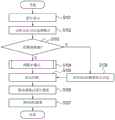
图3是示出根据第一实施例的数字照相机所进行的处理的流程图。FIG. 3 is a flowchart showing processing performed by the digital camera according to the first embodiment.
图4是示出根据第一实施例的数字照相机所进行的AF模式判断的处理的流程图。FIG. 4 is a flowchart showing processing of AF mode determination by the digital camera according to the first embodiment.
图5是各自示出第一实施例中的用以指定AF范围的触摸操作的示例的示意图。5 are schematic diagrams each showing an example of a touch operation to designate an AF range in the first embodiment.
图6是各自示出第一实施例中的根据通过触摸操作指定的AF范围所选择的AF模式的示例的示意图。6 are schematic diagrams each showing an example of an AF mode selected according to an AF range designated by a touch operation in the first embodiment.
图7是示出根据第二实施例的数字照相机的结构的框图。Fig. 7 is a block diagram showing the structure of a digital camera according to the second embodiment.
图8是示出根据第二实施例的数字照相机所进行的处理的流程图。FIG. 8 is a flowchart showing processing performed by the digital camera according to the second embodiment.
图9是示出根据第二实施例的数字照相机所进行的AE模式判断的处理的流程图。FIG. 9 is a flowchart showing processing of AE mode determination by the digital camera according to the second embodiment.
图10是示出根据第三实施例的数字照相机的结构的框图。Fig. 10 is a block diagram showing the structure of a digital camera according to the third embodiment.
图11是示出根据第三实施例的数字照相机所进行的处理的流程图。FIG. 11 is a flowchart showing processing performed by the digital camera according to the third embodiment.
图12是示出根据第三实施例的数字照相机所进行的色温调整模式判断的处理的流程图。FIG. 12 is a flowchart showing processing of color temperature adjustment mode determination performed by the digital camera according to the third embodiment.
图13是示出根据第四实施例的数字照相机所进行的AF模式判断、AE模式判断和色温调整模式判断的处理的流程图。13 is a flowchart showing the processing of AF mode determination, AE mode determination, and color temperature adjustment mode determination performed by the digital camera according to the fourth embodiment.
图14示出第五实施例中作为可以独立地自动选择AF模式、AE模式和色温调整模式这一事实的结果而显示AF框、测光范围框和色温评价范围框的状态。14 shows a state in which an AF frame, a photometry range frame, and a color temperature evaluation range frame are displayed as a result of the fact that AF mode, AE mode, and color temperature adjustment mode can be independently and automatically selected in the fifth embodiment.
具体实施方式Detailed ways
以下将参考附图来说明本发明的优选实施例。Preferred embodiments of the present invention will be described below with reference to the accompanying drawings.
第一实施例first embodiment
首先,将参考图1和2来说明根据第一实施例的用作摄像设备的数字照相机(以下称为照相机)的主要结构。图1是示出根据本实施例的照相机1的内部结构的框图。图2包括照相机1的外观图,其中(a)是正面立体图并且(b)是背面立体图。First, the main structure of a digital camera (hereinafter referred to as a camera) serving as an imaging apparatus according to a first embodiment will be described with reference to FIGS. 1 and 2 . FIG. 1 is a block diagram showing the internal structure of a camera 1 according to the present embodiment. FIG. 2 includes external views of the camera 1, in which (a) is a front perspective view and (b) is a rear perspective view.
在照相机1的正面上设置有包括调焦透镜7的镜头单元2。从镜头单元2入射的光在位于照相机1的内部并且能够进行焦点检测和曝光检测的摄像单元3中成像。摄像单元3使得能够通过使用对电荷累积进行控制的电子快门来进行摄像,并且使得能够输出被摄体图像的通过镜头图像。将从摄像单元3输出的通过镜头图像显示在配置于照相机1的背面的显示单元4上,由此使得拍摄者能够检查构图、曝光和焦点位置。作为快门,可以使用在摄像单元3的前方配置有能够行进的遮光帘幕的机械快门。A
在拍摄者半按下释放按钮5(SW1ON(接通))的情况下,利用摄像单元3开始测光和AF(自动调焦),并且利用镜头单元2内的透镜驱动单元6驱动调焦透镜7。接着,在拍摄者全按下释放按钮5(SW2ON)的情况下,摄像单元3使电子快门行进从而进行摄像。然后,摄像单元3进行开始电荷累积和电荷读出的操作的曝光操作。随后,将所拍摄图像数据记录并保持在照相机1的侧面所设置的图像记录读入单元8内安装的记录介质9中。记录介质9例如是一般的SD卡或CF卡。通过按下图像再现按钮10来将记录并保持在记录介质9中的所拍摄图像显示在显示单元4上。In the case where the photographer half-presses the release button 5 (SW1ON (ON)), photometry and AF (automatic adjustment) are started by the
系统控制电路11是控制照相机1整体的电路,包括CPU或MPU等,并且控制以下将说明的各电路的操作等。The system control circuit 11 is a circuit that controls the camera 1 as a whole, includes a CPU or an MPU, and the like, and controls operations and the like of each circuit that will be described below.
系统控制电路11用作焦点检测单元12。在开始AF时,系统控制电路11基于来自摄像单元3的输出图像来控制透镜驱动单元6,从而在光轴方向上驱动调焦透镜7并由此进行焦点检测。作为焦点检测方法,可以使用诸如摄像面相位差AF或对比度AF方法等的已知方法。在摄像面相位差AF方法中,除了摄像像素以外,摄像单元3还包括均未示出的焦点检测像素群和配置在这些焦点检测像素群前方的光瞳分割透镜群,并且通过利用相位差对摄像面进行焦点检测。在对比度AF方法中,基于所拍摄图像的对比度比来进行焦点检测。可选地,可以使用在光轴方向上前后驱动摄像单元3并且进行对比度AF的摆动方法等。这些焦点检测方法是已知的,因此将省略针对这些焦点检测方法的详细说明。The system control circuit 11 functions as a
系统控制电路11用作聚焦部判断单元29。在焦点检测单元12基于来自摄像单元3的输出图像检测到对比度值的情况下,系统控制电路11基于该对比度值来判断可以聚焦的区域。The system control circuit 11 functions as a focus section determination unit 29 . In a case where the
系统控制电路11用作曝光检测单元13。在开始测光时,系统控制电路11根据拍摄者预先设置的摄像条件,基于来自摄像单元3的输出图像来确定镜头单元2内的光圈14的光圈值和摄像单元3的电子快门速度。在通过全按下释放按钮5(SW2ON)开始摄像操作的情况下,系统控制电路11使曝光控制单元15控制光圈14和电子快门的电荷累积时间以满足所确定的值。The system control circuit 11 functions as an
系统控制电路11使曝光控制单元15通过使用时序发生器16输出驱动摄像单元3时所需的脉冲信号。摄像单元3根据从时序发生器16输出的脉冲信号来进行电荷累积和电荷读出的操作。从摄像单元3读取的电荷由A/D转换电路17进行数字化并且被发送至图像处理电路18。发送至图像处理电路18的图像由图像处理电路18内的图像处理单元19进行白平衡调整和图像压缩处理等,然后由记录控制单元20经由图像记录读入单元8记录并保持在记录介质9中。在按下图像再现按钮10时,记录并保持在记录介质9中的所拍摄图像由图像记录读入单元8读入至图像处理电路18内的显示控制单元21,由D/A转换电路22转换成模拟图像,并且显示在显示单元4上。The system control circuit 11 causes the
镜头单元2不仅可以具有调焦透镜7而且还可以具有变焦透镜等,并且可以具有一体型结构或可更换的单独型结构。此外,在摄像单元3的前方可以可转动地配置有主镜,从而构成用于将来自镜头单元2的光经由五棱镜和成像透镜引入拍摄者的眼睛的光学取景器。此外,在主镜中可转动地设置有辅助镜,并且除基于来自摄像单元3的输出图像进行焦点检测的焦点检测单元12以外,还可以设置使用相位差AF进行工作的焦点检测部件。上述结构是已知的,因此省略了针对这些结构的详细说明。The
使用作为拨盘操作构件的摄像模式选择单元23,可以设置摄像模式。可以设置的摄像模式的示例包括自动曝光模式、光圈优先曝光模式(Av)、快门速度优先曝光模式(Tv)、手动模式(M)和B门模式(B)。在设置自动曝光模式的情况下,拍摄者通过使用作为拨盘操作构件的曝光设置单元24来设置特定适当曝光值,并且在拍摄照片时自动确定光圈值和快门速度从而获得适当曝光。在设置光圈优先曝光模式(Av)、快门速度优先曝光模式(Tv)或手动模式(M)的情况下,可以通过使用光圈值设置单元25和快门速度设置单元26来设置特定光圈值和特定快门速度。在设置B门模式(B)的情况下,通过全按下释放按钮5(SW2ON)来开始摄像,在释放按钮5全按下(SW2ON)期间曝光继续,并且在释放按钮5被释放(SW2OFF(断开))的情况下曝光结束,由此可以在摄像期间确定快门速度。Using the imaging
在显示单元4中,将能够检测接触物的多次接触的电容式传感器叠加在例如用于显示图像的液晶或有机EL显示面板上。在拍摄者利用他或她的手指或者笔等(以下简称为“手指”)接触显示单元4的显示区域的情况下,可以检测到该接触的位置。另外,在拍摄者利用手指接触显示单元4的显示区域并且使手指在显示单元4的显示区域上滑动的情况下,可以检测到该接触的轨迹。电容式传感器包括绝缘膜和配置在该绝缘膜下方的具有格子图案的电极层。在展现导电性的手指接近电容式传感器的情况下,发生从电极层向着手指的静电感应并且这两者之间的绝缘膜的静电容量改变。然后,包括在系统控制电路11中的接近和接触判断部件基于电极层的电位差来读取静电容量的变化,由此使得能够检测到手指的位置。除电容型触摸传感器以外,触摸传感器的示例还包括检测光的反射或明暗的变化的光学型触摸传感器、以及检测手指的按压力的压感型触摸传感器。In the display unit 4 , a capacitive sensor capable of detecting multiple contacts of a contact object is superimposed on, for example, a liquid crystal or organic EL display panel for displaying images. In the case where the photographer touches the display area of the display unit 4 with his or her finger or a pen or the like (hereinafter simply referred to as "finger"), the position of the touch can be detected. In addition, when the photographer touches the display area of the display unit 4 with a finger and slides the finger on the display area of the display unit 4 , the trace of the contact can be detected. A capacitive sensor includes an insulating film and an electrode layer having a lattice pattern arranged under the insulating film. In the case where a finger exhibiting conductivity approaches the capacitive sensor, electrostatic induction from the electrode layer toward the finger occurs and the electrostatic capacity of the insulating film between the two changes. Then, the proximity and contact determination section included in the system control circuit 11 reads the change in the electrostatic capacity based on the potential difference of the electrode layers, thereby enabling detection of the position of the finger. Examples of the touch sensor include an optical type touch sensor that detects reflection of light or a change in brightness and darkness, and a pressure-sensitive type touch sensor that detects a pressing force of a finger, in addition to a capacitive type touch sensor.
系统控制电路11用作作为范围设置部件的AF范围指定区域判断单元27。在拍摄者利用手指接触显示单元4的显示区域从而指定AF范围的情况下,系统控制电路11根据手指进行接触的方式来设置AF范围。例如,如图5(a)所示,在拍摄者利用一个手指接触显示单元4的显示区域的情况下,将包括在该接触部分中的一个局部点设置为AF范围51。如图5(b)所示,在拍摄者利用两个手指接触显示单元4的显示区域的情况下,将由两个手指的接触位置包围的区域或者包括这两个手指的接触位置的区域设置为AF范围51。如图5(c)所示,在拍摄者利用一个手指接触显示单元4的显示区域并且使该一个手指在显示单元4的显示区域上滑动的情况下,将包括在手指滑动的部分中的区域或包括手指滑动的部分的区域设置为AF范围51。除了上述方式以外,指定AF范围的方式的示例还可以包括通过利用三个以上的手指进行接触来进行指定的方式以及通过使手指以矩形或圆形形状滑动来进行指定的方式。The system control circuit 11 functions as an AF range designation area judging unit 27 as a range setting means. In the case where the photographer touches the display area of the display unit 4 with a finger to specify the AF range, the system control circuit 11 sets the AF range according to the way the finger is touched. For example, as shown in FIG. 5( a ), in the case where the photographer touches the display area of the display unit 4 with one finger, one partial point included in the touched portion is set as the
系统控制电路11用作被摄体识别单元28并且基于来自摄像单元3的输出图像来识别与面部相对应的区域和被摄体图像整体。已知如下的面部识别方法,其中在该面部识别方法中,基于肤色、面部的轮廓以及眼睛、鼻子的特征等来提取所拍摄图像内的面部的候选区域,由此基于其特征量来确定面部区域。另外,已知如下方法,其中在该方法中,准备面部形状的多个模板,并且分析这些模板和所拍摄图像之间的相关性,由此根据其相关值来确定面部区域。关于被摄体图像的识别,通过根据颜色、形状和对比度信息使被摄体图像区域与背景分离来提取被摄体图像区域,由此识别被摄体图像。用于识别被摄体的方法是已知的,因此省略了针对该方法的详细说明。The system control circuit 11 functions as a
在根据本实施例的照相机1中,可以在多个AF模式之间改变AF模式。AF自动选择模式切换单元30是用于将AF模式改变为自动选择模式的AF模式的操作构件。如图2所示,AF自动选择模式切换单元30可以作为专用操作构件设置在照相机1上、或者可以设置在通过使用用于改变照相机1整体的设置的菜单按钮能够改变的设置项内。AF模式的示例包括面部追踪AF模式、单点追踪AF模式、多点AF模式和AF自动选择模式,其中在该AF自动选择模式中,根据通过拍摄者进行的触摸操作所指定的AF范围51来自动选择AF模式。In the camera 1 according to the present embodiment, the AF mode can be changed among a plurality of AF modes. The AF automatic selection
在面部追踪AF模式中,如图6(a)的下图所示,被摄体识别单元28追踪作为特定被摄体的面部并进行AF,并且使调焦透镜7进行AF操作。在单点追踪AF模式中,如图6(b)的下图所示,在选择被摄体的一个局部点的情况下,被摄体识别单元28追踪该局部点所定义的部分并进行AF,并且使调焦透镜7进行AF操作。在多点AF模式中,如图6(c)的下图所示,对可以聚焦的被摄体图像整体进行AF,控制诸如光圈值等的摄像条件以使得被摄体图像整体聚焦,并且使调焦透镜7进行AF操作。In the face tracking AF mode, as shown in the lower diagram of FIG. 6( a ), the
系统控制电路11用作AF模式判断单元31。在利用AF自动选择模式切换单元30设置AF自动选择模式的情况下,系统控制电路11根据AF范围指定区域判断单元27所设置的AF范围51内的被摄体识别单元28所获得的面部的识别结果以及聚焦部判断单元29所获得的判断结果来判断AF模式,并且自动选择该AF模式。The system control circuit 11 functions as an AF
将参考图3和4的流程图来说明根据第一实施例的照相机1所进行的处理。在拍摄者接通照相机1的电源的情况下,首先,在步骤S101中系统控制电路11将从摄像单元3供给的通过镜头图像显示在显示单元4上。拍摄者可以通过查看显示单元4上所显示的通过镜头图像来检查构图、曝光和焦点位置。Processing performed by the camera 1 according to the first embodiment will be described with reference to the flowcharts of FIGS. 3 and 4 . When the photographer turns on the power of the camera 1 , first, the system control circuit 11 displays the through-the-lens image supplied from the
在步骤S102中利用AF自动选择模式切换单元30设置AF自动选择模式的情况下,在步骤S103中,系统控制电路11检测拍摄者是否利用手指接触了显示单元4的显示区域从而指定AF范围。When the AF automatic selection
在步骤S103中拍摄者没有利用手指接触显示区域的情况下,该处理进入步骤S108并且进行正常摄像。也就是说,拍摄者通过按下释放按钮5(SW1ON)检测到中央或通过自动AF框选择所获得的聚焦点信息,该处理进入步骤S105,并且系统控制电路11将AF框显示在显示单元4上。然后,在步骤S106中,系统控制电路11使调焦透镜7进行AF操作。在步骤S107中拍摄者全按下释放按钮5(SW2ON)的情况下,进行摄像。In a case where the photographer does not touch the display area with a finger in step S103, the process proceeds to step S108 and normal imaging is performed. That is, the photographer detects the center by pressing the release button 5 (SW1ON) or the focus point information obtained by automatic AF frame selection, the process proceeds to step S105, and the system control circuit 11 displays the AF frame on the display unit 4 superior. Then, in step S106, the system control circuit 11 causes the
在步骤S103中拍摄者利用手指接触了显示区域的情况下,该处理进入步骤S104,并且AF模式判断单元31根据通过拍摄者进行的触摸操作所指定的AF范围51来判断AF模式。In a case where the photographer touches the display area with a finger in step S103, the process proceeds to step S104, and the AF
图4示出步骤S104中的AF模式判断的处理。在根据上述的手指进行接触的方式指定了AF范围51的情况下(步骤S201),被摄体识别单元28在所指定的AF范围51内进行被摄体的识别(步骤S202)。FIG. 4 shows the processing of AF mode determination in step S104. When the
在通过被摄体识别识别出一个或多个面部的情况下(步骤S203中为“是”),焦点检测单元12检测与面部区域αx相对应的来自摄像单元3的输出图像的对比度值βαx(步骤S204)。然后,聚焦部判断单元29将步骤S204中所检测到的对比度值βαx与预设阈值βs进行比较(步骤S205)。在步骤S205中对比度值βαx高于阈值βs的情况下,聚焦部判断单元29判断为存在可以聚焦的面部区域,并且AF模式判断单元31判断为使用面部追踪AF模式并自动选择该面部追踪AF模式(步骤S206)。在步骤S205中对比度值βαx不高于阈值βs的情况下,聚焦部判断单元29判断为不能聚焦(步骤S207)。如图6(c)所示,在拍摄者指定显示单元4的显示区域中的宽范围作为AF范围51的情况下,在识别出面部并且可以聚焦时,判断为要使用面部追踪AF模式。In the case where one or more faces are recognized by subject recognition (YES in step S203), the
在通过被摄体识别没有识别出面部的情况下(步骤S203中为“否”),焦点检测单元12检测与AF范围51相对应的来自摄像单元3的输出图像的对比度值βy(步骤S208)。然后,聚焦部判断单元29将步骤S208中所检测到的对比度值βy与预设阈值βs进行比较(步骤S209)。在步骤S209中,在存在对比度值βy高于阈值βs的区域的情况下,聚焦部判断单元29判断为在对比度值较高的区域中可以聚焦,并且该处理进入步骤S210。在步骤S209中,在不存在对比度值βy高于阈值βs的区域的情况下,聚焦部判断单元29判断为不能聚焦(步骤S213)。In the case where the face is not recognized by subject recognition (NO in step S203), the
在步骤S210中,AF模式判断单元31将可以聚焦的区域的大小γy与预设阈值γs进行比较。在步骤S210中可以聚焦的区域的大小γy大于阈值γs的情况下,AF模式判断单元31判断为使用多点AF模式并且自动选择该多点AF模式(步骤S211)中。如图6(c)所示,在拍摄者指定显示单元4的显示区域中的宽范围作为AF范围51的情况下,在没有识别出面部时,判断为要使用对AF范围51内的可以聚焦的区域整体进行AF的多点AF模式。In step S210, the AF
另一方面,在步骤S210中可以聚焦的区域的大小γy不大于阈值γs的情况下,AF模式判断单元31判断为使用单点追踪AF模式并且自动选择该单点追踪AF模式(步骤S212)。如图6(b)所示,在拍摄者利用一个手指接触显示单元4的显示区域并且指定一个局部点作为AF范围51的情况下,在没有识别出面部时,判断为要使用单点追踪AF模式。On the other hand, in a case where the size γy of the focusable area is not larger than the threshold γs in step S210, the AF
说明现在返回图3。在步骤S104中判断为要使用面部追踪AF模式的情况下,如图6(a)所示,在步骤S105中系统控制电路11在显示单元4上可以聚焦的面部区域中显示AF框(面部检测AF框)61。然后,在步骤S106中,系统控制电路11使调焦透镜7进行AF操作从而聚焦于可以聚焦的面部区域。在步骤S107中拍摄者全按下释放按钮5(SW2ON)的情况下,进行摄像。The description now returns to FIG. 3 . In the case where it is determined in step S104 that the face tracking AF mode is to be used, as shown in FIG. AF box) 61. Then, in step S106 , the system control circuit 11 causes the
在步骤S104中判断为要使用单点追踪AF模式的情况下,如图6(b)所示,在步骤S105中系统控制电路11在显示单元4上可以聚焦的一个点处显示AF框(单点追踪AF框)62。然后,在步骤S106中,系统控制电路11使调焦透镜7进行AF操作从而聚焦于可以聚焦的一个点。在步骤S107中拍摄者全按下释放按钮5(SW2ON)的情况下,进行摄像。In the case where it is determined in step S104 that the single-point tracking AF mode is to be used, as shown in FIG. Point Tracking AF frame) 62. Then, in step S106, the system control circuit 11 causes the
在步骤S104中判断为要使用多点AF模式的情况下,如图6(c)所示,在步骤S105中系统控制电路11在显示单元4上在被摄体图像整体中显示多个点的AF框(多点AF框)63。然后,在步骤S106中,系统控制电路11使调焦透镜7进行AF操作从而聚焦于可以聚焦的被摄体图像整体上。在步骤S107中拍摄者全按下释放按钮5(SW2ON)的情况下,进行摄像。If it is determined in step S104 that the multi-point AF mode is to be used, as shown in FIG. AF frame (multi-point AF frame) 63 . Then, in step S106 , the system control circuit 11 causes the
如上所述,在拍摄者通过触摸操作在显示单元4上指定AF范围51的情况下,根据所指定的AF范围51来自动选择AF模式,由此使得能够快速地改变AF模式。这样可以防止如下问题:在快门释放时机时没有时间改变AF模式,因此难以以最佳AF模式拍摄照片,或者在改变AF模式期间错失了快门释放时机。As described above, in the case where the photographer designates the
本发明不限于上述AF模式,并且可以在本发明的主旨的范围内进行各种变形和改变。作为AF模式的示例,给出了从一个局部点起扩大AF范围的区域AF等。例如,在步骤S104中判断为要使用单点追踪AF模式的情况下,在显示单元4上的大致相同范围内再次检测到利用拍摄者的手指的多次接触的情况下,可以判断为要使用区域AF模式。在这种情况下,AF框可以根据所检测到的接触次数从1个点、5个点、9个点和13个点起顺次增大。The present invention is not limited to the above-mentioned AF mode, and various modifications and changes can be made within the scope of the gist of the present invention. As an example of the AF mode, area AF, which expands the AF range from one local point, and the like are given. For example, in the case where it is determined in step S104 that the single-point tracking AF mode is to be used, it may be determined that the single-point tracking AF mode is to be used when multiple touches with the photographer's fingers are detected again in approximately the same range on the display unit 4. Zone AF mode. In this case, the AF frame may be sequentially increased from 1 dot, 5 dots, 9 dots, and 13 dots according to the number of detected contacts.
可以改变诸如单次调焦模式和伺服调焦模式等的调焦模式。单次调焦模式是在镜头单元2根据来自焦点检测单元12的输出聚焦于被摄体之后焦点固定的模式。伺服调焦模式是通过在所聚焦的被摄体移动的情况下跟随焦点来维持聚焦于被摄体的模式。例如,在步骤S104中,在拍摄者利用手指接触显示单元4从而指定要聚焦的被摄体、并且在手指接触显示单元4的状态下使手指以跟随移动中的被摄体的方式进行滑动的情况下,AF模式判断单元31判断为使用伺服调焦模式并且自动选择该伺服调焦模式。在拍摄者使手指离开显示单元4而不使手指在显示单元4上滑动的情况下,AF模式判断单元31判断为使用单次调焦模式并且自动选择该单次调焦模式。Focusing modes such as one-shot focusing mode and servo focusing mode can be changed. The one-shot focus mode is a mode in which the focus is fixed after the
第二实施例second embodiment
在第一实施例中,说明了自动选择AF模式的示例;可选地,可以自动选择AE(自动曝光)模式。In the first embodiment, an example of automatically selecting the AF mode was explained; alternatively, an AE (Auto Exposure) mode may be automatically selected.
将参考图7来说明根据第二实施例的用作摄像设备的数字照相机(以下称为照相机)的主要结构。利用相同的附图标记来表示与根据第一实施例的照相机1的组件相同的组件,并且省略了针对这些组件的说明。The main structure of a digital camera (hereinafter referred to as a camera) serving as an imaging apparatus according to a second embodiment will be described with reference to FIG. 7 . The same components as those of the camera 1 according to the first embodiment are denoted by the same reference numerals, and explanations for these components are omitted.
在第二实施例中,如图7所示,代替第一实施例中的AF范围指定区域判断单元27、AF自动选择模式切换单元30和AF模式判断单元31,照相机1包括AE范围指定区域判断单元32、AE自动选择模式切换单元33和AE模式判断单元34。与AF自动选择模式切换单元30相同,AE自动选择模式切换单元33可以作为专用操作构件设置在照相机1上、或者可以设置在通过使用用于改变照相机1整体的设置的菜单按钮能够改变的设置项内。In the second embodiment, as shown in FIG. 7, instead of the AF range designation area judging unit 27, the AF automatic selection
在第二实施例中,系统控制电路11用作作为范围设置部件的AE范围指定区域判断单元32。在拍摄者利用手指接触显示单元4的显示区域从而指定AE范围的情况下,系统控制电路11根据该手指进行接触的方式来设置AE范围。例如,在拍摄者利用一个手指接触显示单元4的显示区域的情况下,与图5(a)所示的AF范围51相同,将包括在该接触部分中的一个局部点设置为AE范围。在拍摄者利用两个手指接触显示单元4的显示区域的情况下,与图5(b)所示的AF范围51相同,将由两个手指的接触位置包围的区域或包括这两个手指的接触位置的区域设置为AE范围。在拍摄者利用一个手指接触显示单元4的显示区域并且使该一个手指在显示单元4的显示区域上滑动的情况下,与图5(c)所示的AF范围51相同,将手指滑动的部分中所包括的区域或包括手指滑动的部分的区域设置为AE范围。除了上述方式以外,指定AE范围的方式的示例还可以包括通过利用三个以上的手指进行接触来进行指定的方式和通过使手指以矩形或圆形形状滑动来进行指定的方式。In the second embodiment, the system control circuit 11 functions as the AE range designation
系统控制电路11用作AE模式判断单元34。在利用AE自动选择模式切换单元33设置AE自动选择模式的情况下,系统控制电路11根据AE范围指定区域判断单元32所设置的AE范围内的被摄体识别单元28所获得的面部的识别结果以及聚焦部判断单元29所获得的判断结果来判断AE模式,并且自动选择该AE模式。在本实施例中,AE自动选择模式中进行判断的AE模式的示例包括面部追踪测光模式、单点追踪测光模式和被摄体评价测光模式,其中:在该面部追踪测光模式中,被摄体识别单元28追踪被摄体的面部并且进行测光;在该单点追踪测光模式中,被摄体识别单元28追踪被摄体的一个局部点并且进行测光;以及在该被摄体评价测光模式中,对被摄体整体进行测光。曝光检测单元13从来自摄像单元3的输出检测亮度信息,并且进行测光。The system control circuit 11 functions as the AE
将参考图8和9的流程图来说明根据第二实施例的照相机1所进行的处理。在拍摄者接通照相机1的电源的情况下,首先,在步骤S301中系统控制电路11将从摄像单元3供给的通过镜头图像显示在显示单元4上。拍摄者可以通过查看显示单元4上所显示的通过镜头图像来检查构图、曝光和焦点位置。Processing performed by the camera 1 according to the second embodiment will be described with reference to the flowcharts of FIGS. 8 and 9 . When the photographer turns on the power of the camera 1 , first, the system control circuit 11 displays the through-the-lens image supplied from the
在步骤S302中利用AE自动选择模式切换单元33设置AE自动选择模式的情况下,在步骤S203中,系统控制电路11检测拍摄者是否利用手指接触了显示单元4的显示区域从而指定AE范围。When the AE automatic selection mode is set by the AE automatic selection
在步骤S303中拍摄者没有利用手指接触显示区域的情况下,该处理进入步骤S308并且进行正常摄像。也就是说,拍摄者通过按下释放按钮5(SW1ON)来检测特定测光信息,该处理进入步骤S305,并且系统控制电路11将测光范围框显示在显示单元4上。然后,在步骤S306中进行AE操作。在步骤S307中拍摄者全按下释放按钮5(SW2ON)的情况下,进行摄像。In a case where the photographer does not touch the display area with a finger in step S303, the process proceeds to step S308 and normal imaging is performed. That is, the photographer detects specific photometry information by pressing the release button 5 (SW1ON), the process proceeds to step S305, and the system control circuit 11 displays the photometry range frame on the display unit 4. Then, the AE operation is performed in step S306. When the photographer fully presses the release button 5 (SW2ON) in step S307, imaging is performed.
在步骤S303中拍摄者利用手指接触了显示区域的情况下,该处理进入步骤S304,并且AE模式判断单元34根据通过拍摄者进行的触摸操作所指定的AE范围来判断AE模式。In a case where the photographer touches the display area with a finger in step S303, the process proceeds to step S304, and the AE
图9示出步骤S304中的AE模式判断的处理。利用相同的附图标记来表示与第一实施例所述的图4的流程图中的处理相同的处理,并且省略了针对这些处理的说明。在根据上述的手指进行接触的方式指定AE范围的情况下(步骤S401),进行步骤S202~S202和步骤S208~S210的判断。在步骤S205中对比度值βαx高于阈值βs的情况下,判断为存在可以聚焦的面部区域,并且AE模式判断单元34判断为使用面部追踪AE模式并且自动选择该面部追踪AE模式(步骤S402)。在步骤S210中可以聚焦的区域的大小γy大于阈值γs的情况下,AE模式判断单元34判断为使用被摄体评价AE模式并且自动选择该被摄体评价AE模式(步骤S403)。另一方面,在步骤S210中可以聚焦的区域的大小γy不大于阈值γs的情况下,AE模式判断单元34判断为使用单点追踪AE模式并且自动选择该单点追踪AE模式(步骤S404)。FIG. 9 shows the processing of the AE mode determination in step S304. The same processes as those in the flowchart of FIG. 4 described in the first embodiment are denoted by the same reference numerals, and explanations for these processes are omitted. When the AE range is specified based on the above-mentioned manner of finger contact (step S401), the judgments in steps S202 to S202 and steps S208 to S210 are performed. In the case where the contrast value βαx is higher than the threshold βs in step S205, it is determined that there is a face area that can be focused, and the AE
现在说明将返回至图8。在步骤S304中判断为要使用面部追踪AE模式的情况下,与图6(a)所示的AF框(面部检测AF框)61相同,在步骤S305中系统控制电路11在显示单元4上可以聚焦的面部区域中显示测光范围框。然后,在步骤S306中对可以聚焦的面部区域进行AE操作。在步骤S307中拍摄者全按下释放按钮5(SW2ON)的情况下,进行摄像。The description will now return to FIG. 8 . In the case where it is determined in step S304 that the face tracking AE mode is to be used, the same as the AF frame (face detection AF frame) 61 shown in FIG. The metering range frame is displayed in the focused face area. Then, in step S306, the AE operation is performed on the face area that can be focused. When the photographer fully presses the release button 5 (SW2ON) in step S307, imaging is performed.
在步骤S304中判断为要使用单点追踪AE模式的情况下,与图6(b)所示的AF框(单点追踪AE框)62相同,在步骤S305中系统控制电路11在显示单元4上可以聚焦的一个点处显示测光范围框。然后,在步骤S306中对可以聚焦的一个点进行AE操作。在步骤S307中拍摄者全按下释放按钮5(SW2ON)的情况下,进行摄像。In the case where it is determined in step S304 that the single-point tracking AE mode is to be used, the same as the AF frame (single-point tracking AE frame) 62 shown in FIG. A metering range frame is displayed at a point on which the camera can focus. Then, in step S306, an AE operation is performed on a point that can be focused. When the photographer fully presses the release button 5 (SW2ON) in step S307, imaging is performed.
在步骤S304中判断为要使用被摄体评价AE模式的情况下,与图6(c)所示的AF框(多点AF框)63相同,在步骤S305中系统控制电路11在显示单元4上在被摄体图像整体中显示多个点的测光范围框。然后,在步骤S306中对可以聚焦的被摄体图像整体进行AE操作。在步骤S307中拍摄者全按下释放按钮5(SW2ON)的情况下,进行摄像。In the case where it is determined in step S304 that the subject evaluation AE mode is to be used, the same as the AF frame (multi-point AF frame) 63 shown in FIG. A metering range frame that displays multiple points in the entire subject image. Then, in step S306, the AE operation is performed on the entire subject image that can be focused. When the photographer fully presses the release button 5 (SW2ON) in step S307, imaging is performed.
第三实施例third embodiment
说明了第一实施例中的自动选择AF模式的示例和第二实施例中的自动选择AE模式的示例;可选地,可以自动选择色温调整模式。An example of automatically selecting the AF mode in the first embodiment and an example of automatically selecting the AE mode in the second embodiment were explained; alternatively, the color temperature adjustment mode may be automatically selected.
将参考图10来说明根据第三实施例的用作摄像设备的数字照相机(以下称为照相机)的主要结构。利用相同的附图标记来表示与根据第一实施例的照相机1的组件相同的组件,并且省略了针对这些组件的说明。The main structure of a digital camera (hereinafter referred to as a camera) serving as an imaging apparatus according to a third embodiment will be described with reference to FIG. 10 . The same components as those of the camera 1 according to the first embodiment are denoted by the same reference numerals, and explanations for these components are omitted.
在第三实施例中,如图10所示,代替第一实施例中的AF范围指定区域判断单元27、AF自动选择模式切换单元30和AF模式判断单元31,照相机1包括色温评价范围指定区域判断单元35、色温调整自动选择模式切换单元36和色温调整模式判断单元37。与AF自动选择模式切换单元30和AE自动选择模式切换单元33相同,色温调整自动选择模式切换单元36可以作为专用操作构件设置在照相机1上、或者可以设置在通过使用用于改变照相机1整体的设置的菜单按钮能够改变的设置项内。In the third embodiment, as shown in FIG. 10 , instead of the AF range designation area judging unit 27, the AF automatic selection
在第三实施例中,系统控制电路11用作作为范围设置部件的色温评价范围指定区域判断单元35。在拍摄者利用手指接触显示单元4的显示区域从而指定色温评价范围的情况下,系统控制电路11根据手指进行接触的方式来设置色温评价范围。例如,在拍摄者利用一个手指接触显示单元4的显示区域的情况下,与图5(a)所示的AF范围51相同,将该接触部分中所包括的一个局部点设置为色温评价范围。在拍摄者利用两个手指接触显示单元4的显示区域的情况下,与图5(b)所示的AF范围51相同,将由两个手指的接触位置包围的区域或包括这两个手指的接触位置的区域设置为色温评价范围。在拍摄者利用一个手指接触显示单元4的显示区域并且使该一个手指在显示单元4的显示区域上滑动的情况下,与图5(c)所示的AF范围51相同,将手指滑动的部分中所包括的区域或包括手指滑动的部分的区域设置为色温评价范围。除上述方式以外,指定色温评价范围的方式的示例还可以包括通过利用三个以上的手指进行接触来进行指定的方式和通过使手指以矩形或圆形形状滑动来进行指定的方式。In the third embodiment, the system control circuit 11 functions as the color temperature evaluation range designation
系统控制电路11用作色温调整模式判断单元37。在利用色温调整自动选择模式切换单元36设置色温调整自动选择模式的情况下,系统控制电路11根据色温评价范围指定区域判断单元35所设置的色温评价范围内的被摄体识别单元28所获得的面部的识别结果以及聚焦部判断单元29所获得的判断结果来判断色温调整模式,并且自动选择该色温调整模式。在本实施例中,色温调整自动选择模式中进行判断的色温调整模式的示例包括面部追踪色温调整模式、光源色温调整模式和自动色温调整模式,其中:在该面部追踪色温调整模式中,被摄体识别单元28追踪被摄体的面部并且根据肌肤的颜色来调整色温;在该光源色温调整模式中,曝光检测单元13检测亮度高的光源并且根据光源的颜色来调整色温;以及在该自动色温调整模式中,根据被摄体整体的大致平均色温来调整色温。图像处理电路18根据来自摄像单元3的输出的颜色信息来评价并调整色温。The system control circuit 11 functions as a color temperature adjustment
将参考图11和12的流程图来说明根据第三实施例的照相机1所进行的处理。在拍摄者接通照相机1的电源的情况下,首先,在步骤S501中系统控制电路11将从摄像单元3供给的通过镜头图像显示在显示单元4上。拍摄者可以通过查看显示单元4上所显示的通过镜头图像来检查构图、曝光和焦点位置。Processing performed by the camera 1 according to the third embodiment will be described with reference to the flowcharts of FIGS. 11 and 12 . When the photographer turns on the power of the camera 1 , first, the system control circuit 11 displays the through-the-lens image supplied from the
在步骤S502中利用色温调整自动选择模式切换单元36设置色温调整自动选择模式的情况下,在步骤S503中,系统控制电路11检测拍摄者是否利用手指接触了显示单元4的显示区域从而指定色温评价范围。In the case where the color temperature adjustment automatic selection mode is set by the color temperature adjustment automatic selection mode switching unit 36 in step S502, in step S503, the system control circuit 11 detects whether the photographer touches the display area of the display unit 4 with a finger to designate the color temperature evaluation. scope.
在步骤S503中拍摄者没有利用手指接触显示区域的情况下,该处理进入步骤S508并且进行正常摄像。也就是说,拍摄者通过按下释放按钮5(SW1ON)来检测特定色温信息,该处理进入步骤S505,并且系统控制电路11将色温评价范围框显示在显示单元4上。然后,在步骤S506中进行色温调整操作。在步骤S507中拍摄者全按下释放按钮5(SW2ON)的情况下,进行摄像。In a case where the photographer does not touch the display area with a finger in step S503, the process proceeds to step S508 and normal imaging is performed. That is, the photographer detects specific color temperature information by pressing the release button 5 (SW1ON), the process proceeds to step S505, and the system control circuit 11 displays a color temperature evaluation range frame on the display unit 4. Then, a color temperature adjustment operation is performed in step S506. When the photographer fully presses the release button 5 (SW2ON) in step S507, imaging is performed.
在步骤S503中拍摄者利用手指接触了显示区域的情况下,该处理进入步骤S504,并且色温调整模式判断单元37根据通过拍摄者进行的触摸操作所指定的色温评价范围来判断色温调整模式。In a case where the photographer touches the display area with a finger in step S503, the process proceeds to step S504, and the color temperature adjustment
图12示出步骤S504中的色温调整模式判断的处理。利用相同的附图标记来表示与第一实施例所述的图4的流程图中的处理相同的处理,并且省略了针对这些处理的说明。在根据上述的手指进行接触的方式指定色温评价范围的情况下(步骤S601),进行步骤S202~S205以及步骤S208和S209的判断。在步骤S205中对比度值βαx高于阈值βs的情况下,判断为存在可以聚焦的面部区域,并且色温调整模式判断单元37判断为使用面部追踪色温调整模式并且自动选择该面部追踪色温调整模式(步骤S602)。FIG. 12 shows the processing of the color temperature adjustment mode determination in step S504. The same processes as those in the flowchart of FIG. 4 described in the first embodiment are denoted by the same reference numerals, and explanations for these processes are omitted. When the color temperature evaluation range is specified based on the manner in which the finger touches as described above (step S601 ), the judgments in steps S202 to S205 and steps S208 and S209 are performed. In the case where the contrast value βαx is higher than the threshold βs in step S205, it is determined that there is a face area that can be focused, and the color temperature adjustment
在步骤S209中,在存在对比度值βy高于阈值βs的区域的情况下,判断为在对比度值较高的区域中可以聚焦,并且该处理进入步骤S603。在步骤S603中,色温调整模式判断单元37将可以聚焦的区域的亮度δα与预设阈值δs进行比较。在步骤S603中可以聚焦的区域的亮度δα高于阈值δs的情况下,色温调整模式判断单元37判断为使用光源色温调整模式并且自动选择该光源色温调整模式(步骤S604)。另一方面,在步骤S603中可以聚焦的区域的亮度δα不高于阈值δs的情况下,色温调整模式判断单元37判断为使用自动色温调整模式并且自动选择该自动色温调整模式(步骤S605)。In step S209, in a case where there is an area where the contrast value βy is higher than the threshold value βs , it is determined that focusing is possible in the area where the contrast value is high, and the process proceeds to step S603. In step S603, the color temperature adjustment
现在说明将返回至图11。在步骤S504中判断为要使用面部追踪色温调整模式的情况下,与图6(a)所示的AF框(面部检测AF框)61相同,系统控制电路11在显示单元4上可以聚焦的面部区域中显示色温评价范围框。然后,在步骤S506中,对可以聚焦的面部区域进行色温评价并且进行色温调整操作。在步骤S507中拍摄者全按下释放按钮5(SW2ON)的情况下,进行摄像。The description will now return to FIG. 11 . In the case where it is determined in step S504 that the face tracking color temperature adjustment mode is to be used, the system control circuit 11 can focus on the face on the display unit 4 similarly to the AF frame (face detection AF frame) 61 shown in FIG. 6( a ). The color temperature evaluation range box is displayed in the area. Then, in step S506 , the color temperature evaluation and color temperature adjustment operation are performed on the face area that can be focused. When the photographer fully presses the release button 5 (SW2ON) in step S507, imaging is performed.
在步骤S504中判断为要使用自动色温调整模式的情况下,在步骤S505中,系统控制电路11在被摄体整体内扩大色温评价范围从而将色温测光范围框显示在显示单元4上。然后,在步骤S506中,检测色温评价范围框中被摄体的大致平均色温并且进行色温调整操作。在步骤S507中拍摄者全按下释放按钮5(SW2ON)的情况下,进行摄像。If it is determined in step S504 that the automatic color temperature adjustment mode is to be used, in step S505 , the system control circuit 11 expands the color temperature evaluation range within the entire subject to display a color temperature photometry range frame on the display unit 4 . Then, in step S506 , the approximate average color temperature of the subject in the color temperature evaluation range frame is detected and a color temperature adjustment operation is performed. When the photographer fully presses the release button 5 (SW2ON) in step S507, imaging is performed.
在步骤S504中判断为要使用光源色温调整模式的情况下,在步骤S505中,曝光检测单元13检测色温评价范围中的亮度高的光源部的色温,并且系统控制电路11将色温测光范围框显示在显示单元4上。然后,在步骤S506中进行色温调整操作。在步骤S507中拍摄者全按下释放按钮5(SW2ON)的情况下,进行摄像。In the case where it is determined in step S504 that the light source color temperature adjustment mode is to be used, in step S505, the
第四实施例Fourth embodiment
说明了第一实施例中的自动选择AF模式的示例、第二实施例中的自动选择AE模式的示例和第三实施例中的自动选择色温调整模式的示例;可选地,可以使这些操作彼此连动。An example of automatically selecting the AF mode in the first embodiment, an example of automatically selecting the AE mode in the second embodiment, and an example of automatically selecting the color temperature adjustment mode in the third embodiment have been described; alternatively, these operations can be made Link each other.
例如,如图13所示,与第一实施例相同,判断并自动选择面部追踪AF模式、多点AF模式或单点追踪AF模式(步骤S201~步骤S212)。For example, as shown in FIG. 13 , as in the first embodiment, face tracking AF mode, multi-point AF mode or single point tracking AF mode is judged and automatically selected (step S201 to step S212 ).
然后,在步骤S206中自动选择面部追踪AF模式的情况下,自动选择面部追踪AE模式(步骤S402),其中在该面部追踪AE模式,将可以聚焦的面部区域用作测光范围框。另外,自动选择面部追踪色温调整模式(步骤S602),其中在该面部追踪色温调整模式中,将可以聚焦的面部区域用作色温评价范围框。Then, in a case where the face-tracking AF mode is automatically selected in step S206, the face-tracking AE mode in which a face area that can be focused is used as a metering range frame is automatically selected (step S402). In addition, a face tracking color temperature adjustment mode is automatically selected (step S602 ), in which a face area that can be focused is used as a color temperature evaluation range frame.
另一方面,在步骤S211中自动选择多点AF模式的情况下,自动选择被摄体评价AE模式(步骤S403),其中在该被摄体评价AE模式中,在被摄体图像整体中设置多个点的测光范围框。在步骤S212中自动选择单点追踪AF模式的情况下,自动选择单点追踪AE模式(步骤S404),其中在该单点追踪AE模式中,将可以聚焦的一个点用作测光范围框。On the other hand, in the case where the multi-point AF mode is automatically selected in step S211, the subject evaluation AE mode in which the subject image is set as a whole is automatically selected (step S403). Metering range box for multiple points. In a case where the single-point tracking AF mode is automatically selected in step S212, the single-point tracking AE mode in which one point that can be focused is used as a photometry range frame is automatically selected (step S404).
然后,在自动选择被摄体评价AE模式和单点追踪AE模式的情况下,该处理进入步骤S603,并且将可以聚焦的区域的亮度δα与预设阈值δs进行比较。在步骤S603中可以聚焦的区域的亮度δα高于阈值δs的情况下,判断为要使用光源色温调整模式并且自动选择该光源色温调整模式(步骤S604)。在可以聚焦的区域的亮度δα不高于阈值δs的情况下,判断为要使用自动色温调整模式并且自动选择该自动色温调整模式(步骤S605)。Then, in the case of automatically selecting the subject evaluation AE mode and the single-point tracking AE mode, the process proceeds to step S603, and the brightness δα of the focusable area is compared with a preset threshold value δs . If the luminance δα of the focusable area is higher than the threshold δs in step S603, it is determined that the light source color temperature adjustment mode is to be used and the light source color temperature adjustment mode is automatically selected (step S604). In the case where the luminance δα of the focusable area is not higher than the threshold δs , it is determined that the automatic color temperature adjustment mode is to be used and is automatically selected (step S605).
第五实施例fifth embodiment
在第四实施例中,说明了还与AF模式的自动选择连动地自动选择AE模式和色温调整模式的示例;可选地,在一系列操作中,可以独立地自动选择AF模式、AE模式和色温调整模式。In the fourth embodiment, an example in which the AE mode and the color temperature adjustment mode are also automatically selected in conjunction with the automatic selection of the AF mode is described; and color temperature adjustment mode.
在本实施例中,为了在一系列操作中可以独立地自动选择AF模式、AE模式和色温调整模式,系统控制电路11配备有作为接触顺序检测部件的功能,其中该接触顺序检测部件用于在拍摄者利用手指多次接触显示单元4的情况下检测接触的顺序。In the present embodiment, in order that the AF mode, the AE mode, and the color temperature adjustment mode can be independently and automatically selected in a series of operations, the system control circuit 11 is equipped with a function as a contact sequence detection section for When the photographer touches the display unit 4 multiple times with a finger, the sequence of touches is detected.
在本实施例中,将参考图3和8来说明按顺序依次独立地自动选择AF模式和AE模式的示例。In this embodiment, an example in which the AF mode and the AE mode are automatically selected sequentially and independently will be described with reference to FIGS. 3 and 8 .
在将从摄像单元3供给的通过镜头图像显示在显示单元4的状态下,检查手指是否接触了显示单元4的显示区域(图3的步骤S103)。在检测到手指的接触的情况下,进行图3的步骤S104、S105和S106的处理。In a state where the through-the-lens image supplied from the
随后,在拍摄者全按下释放按钮5(SW2ON)之前,在特定条件下检测手指是否接触了显示单元4的显示区域(图8的步骤S303)。在检测到手指的接触的情况下,进行图8的步骤S304、S305和S306的处理。作为特定条件,例如,可以是在仍维持第一次的手指的接触(步骤S103)的状态下进行另一手指的接触(步骤S503)的条件。此外,可以是在进行了手指的第一次接触(步骤S103)并且释放该接触之后、在特定时间段内进行该手指的第二次接触(步骤S503)的条件。Subsequently, before the photographer fully presses the release button 5 (SW2ON), it is detected whether or not the finger touches the display area of the display unit 4 under certain conditions (step S303 of FIG. 8 ). When the contact of a finger is detected, the processing of steps S304, S305, and S306 in FIG. 8 is performed. As a specific condition, for example, it may be a condition that another finger touches (step S503 ) while the first finger touch (step S103 ) is maintained. Also, there may be a condition that the second contact of the finger (step S503 ) is made within a certain period of time after the first contact of the finger is made (step S103 ) and the contact is released.
之后,在拍摄者全按下释放按钮5(SW2ON)的情况下,进行摄像。Thereafter, when the photographer fully presses the release button 5 (SW2ON), imaging is performed.
在本实施例中,说明了独立地自动选择AF模式和AE模式的示例;可选地,可以独立地自动选择AF模式、AE模式和色温调整模式的任何组合。例如可以在菜单设置中改变自动选择的顺序。In this embodiment, an example of automatically selecting the AF mode and the AE mode independently is described; alternatively, any combination of the AF mode, the AE mode and the color temperature adjustment mode may be independently automatically selected. For example, the order of automatic selection can be changed in the menu settings.
图14示出作为可以独立地自动选择AF模式、AE模式和色温调整模式这一事实的结果而显示AF框、测光范围框和色温评价范围框的状态。FIG. 14 shows a state in which an AF frame, a photometry range frame, and a color temperature evaluation range frame are displayed as a result of the fact that the AF mode, the AE mode, and the color temperature adjustment mode can be independently and automatically selected.
第六实施例Sixth embodiment
如第一实施例所述并且如图5(a)所示,在拍摄者利用一个手指接触显示单元4的显示区域的情况下,将该接触部分中所包括的一个局部点设置为AF范围51。此时,系统控制电路11检测接触时间T。As described in the first embodiment and as shown in FIG. . At this time, the system control circuit 11 detects the contact time T.
随后,在使调焦透镜7进行AF操作的情况下(步骤S106),根据接触时间T来设置直到调焦透镜7聚焦为止的驱动时间。例如,将直到调焦透镜7聚焦为止的驱动时间设置为接触时间T。Subsequently, in the case of subjecting the
在本实施例中,说明了AF模式作为示例;然而,本实施例还可应用于AE模式和色温调整模式的自动选择。在自动选择AE模式的情况下,根据接触时间T来设置曝光控制单元15所控制的摄像单元3的曝光量的改变时间,并且进行测光。在自动选择色温调整模式的情况下,根据接触时间T来设置图像处理电路18所控制的色温调整(改变)时间,并且调整来自摄像单元3的输出图像的色温。In the present embodiment, the AF mode was explained as an example; however, the present embodiment is also applicable to automatic selection of the AE mode and the color temperature adjustment mode. In the case of automatically selecting the AE mode, the change time of the exposure amount of the
如本实施例那样,根据接触时间T来设置直到调焦透镜7聚焦为止的驱动时间,由此例如在拍摄运动图像的情况下,使得用户能够容易地控制如动画那样的慢聚焦。As in the present embodiment, the drive time until the
以上说明了本发明的优选实施例;然而,本发明不限于这些实施例,并且可以在本发明的主旨的范围内进行各种变形和改变。The preferred embodiments of the present invention have been described above; however, the present invention is not limited to these embodiments, and various modifications and changes can be made within the scope of the gist of the present invention.
其它实施例other embodiments
还可以通过执行以下处理来实现本发明:将实现上述实施例的功能的软件(程序)经由网络或各种存储介质供给至系统或设备,并且该系统或设备的计算机(CPU或MPU等)读取并执行该程序。The present invention can also be realized by performing a process in which software (program) realizing the functions of the above-described embodiments is supplied to a system or device via a network or various storage media, and a computer (CPU or MPU, etc.) of the system or device reads Fetch and execute the program.
另外,在上述实施例中,作为使用焦点检测像素的输出的校正处理的一个例子说明了串扰校正处理,但是,基于异常输出进行校正处理的问题不限于发生在串扰校正处理中。另外,上述特征也可能适用于进行其它校正处理的情况。所以,不应该将本发明的适用范围限定解释为串扰校正处理。Also, in the above-described embodiments, crosstalk correction processing was described as an example of correction processing using outputs of focus detection pixels, but the problem of correction processing based on abnormal outputs is not limited to occur in crosstalk correction processing. In addition, the above features may also be applicable to the case of performing other correction processes. Therefore, the scope of application of the present invention should not be construed as a crosstalk correction process.
另外,在上述实施例中,说明了CPU121以软件方式执行处理的结构。然而,这些处理中的至少一部分处理可以由硬件(ASIC、可编程逻辑等)来执行。In addition, in the above-described embodiments, the configuration in which the CPU 121 executes processing by software has been described. However, at least some of these processes may be performed by hardware (ASIC, programmable logic, etc.).
本发明不限于上述实施例,并且可以在没有背离本发明的精神和范围的情况下进行各种改变和变形。因此,为了公开本发明的范围,追加了以下权利要求项。The present invention is not limited to the above-described embodiments, and various changes and modifications can be made without departing from the spirit and scope of the present invention. Therefore, in order to disclose the scope of the present invention, the following claims are appended.
本申请要求2011年10月12日提交的日本专利申请2011-225264和2012年9月19日提交的日本专利申请2012-205997的优先权,在此通过引用包含这两个申请的全部内容。This application claims priority from Japanese Patent Application No. 2011-225264 filed on October 12, 2011 and Japanese Patent Application No. 2012-205997 filed on September 19, 2012, the entire contents of which are hereby incorporated by reference.
Claims (16)
Applications Claiming Priority (5)
| Application Number | Priority Date | Filing Date | Title |
|---|---|---|---|
| JP2011-225264 | 2011-10-12 | ||
| JP2011225264 | 2011-10-12 | ||
| JP2012-205997 | 2012-09-19 | ||
| JP2012205997A JP6083987B2 (en) | 2011-10-12 | 2012-09-19 | Imaging apparatus, control method thereof, and program |
| PCT/JP2012/075762 WO2013054726A1 (en) | 2011-10-12 | 2012-10-04 | Imaging device, and method and program for controlling same |
Publications (2)
| Publication Number | Publication Date |
|---|---|
| CN103858043A true CN103858043A (en) | 2014-06-11 |
| CN103858043B CN103858043B (en) | 2017-11-28 |
Family
ID=48081782
Family Applications (1)
| Application Number | Title | Priority Date | Filing Date |
|---|---|---|---|
| CN201280050338.7A Expired - Fee Related CN103858043B (en) | 2011-10-12 | 2012-10-04 | Picture pick-up device and its control method |
Country Status (5)
| Country | Link |
|---|---|
| US (1) | US20130155276A1 (en) |
| JP (1) | JP6083987B2 (en) |
| CN (1) | CN103858043B (en) |
| TW (1) | TWI549501B (en) |
| WO (1) | WO2013054726A1 (en) |
Cited By (9)
| Publication number | Priority date | Publication date | Assignee | Title |
|---|---|---|---|---|
| CN104219518A (en) * | 2014-07-31 | 2014-12-17 | 小米科技有限责任公司 | Photometry method and device |
| CN104320654A (en) * | 2014-10-28 | 2015-01-28 | 小米科技有限责任公司 | Light metering method and device |
| CN105827994A (en) * | 2016-04-12 | 2016-08-03 | 乐视控股(北京)有限公司 | System and method for solving problem of focusing area overexposure |
| US9674454B2 (en) | 2014-07-31 | 2017-06-06 | Xiaomi Inc. | Light metering methods and devices |
| WO2017166076A1 (en) * | 2016-03-29 | 2017-10-05 | 华为技术有限公司 | Method, device and apparatus for determining focus window |
| CN107736009A (en) * | 2015-06-16 | 2018-02-23 | 奥林巴斯株式会社 | Computing method, computing program and photographing device |
| CN109074222A (en) * | 2016-04-19 | 2018-12-21 | 麦克赛尔株式会社 | mobile terminal device |
| CN110062155A (en) * | 2019-03-25 | 2019-07-26 | 成都品果科技有限公司 | A kind of portrait based on automatic light measuring is taken pictures optimization system, method and apparatus |
| CN110741627A (en) * | 2017-06-21 | 2020-01-31 | 富士胶片株式会社 | Imaging device, control method of imaging device, and control program of imaging device |
Families Citing this family (23)
| Publication number | Priority date | Publication date | Assignee | Title |
|---|---|---|---|---|
| JP5949306B2 (en) * | 2012-08-13 | 2016-07-06 | 株式会社ニコン | Image processing apparatus, imaging apparatus, and image processing program |
| KR101918760B1 (en) * | 2012-10-30 | 2018-11-15 | 삼성전자주식회사 | Imaging apparatus and control method |
| JP5949591B2 (en) * | 2013-02-13 | 2016-07-06 | ソニー株式会社 | Imaging apparatus, control method, and program |
| KR102034583B1 (en) * | 2013-02-28 | 2019-10-21 | 엘지전자 주식회사 | Digital device and method for controlling the same |
| JP2015032640A (en) * | 2013-07-31 | 2015-02-16 | 株式会社東芝 | Solid-state imaging device and method for manufacturing solid-state imaging device |
| JP6164978B2 (en) * | 2013-08-21 | 2017-07-19 | キヤノン株式会社 | FOCUS ADJUSTMENT DEVICE, ITS CONTROL METHOD, CONTROL PROGRAM, AND IMAGING DEVICE |
| CN103841390B (en) | 2014-02-22 | 2015-06-17 | 深圳市中兴移动通信有限公司 | Shooting method and device |
| TWI524251B (en) * | 2014-02-24 | 2016-03-01 | 原相科技股份有限公司 | Capacitive finger navigation module and manufacturing method thereof |
| US9203951B1 (en) * | 2014-07-03 | 2015-12-01 | International Business Machines Corporation | Mobile telephone adapted for use with one hand |
| JP6512810B2 (en) * | 2014-12-11 | 2019-05-15 | キヤノン株式会社 | Image pickup apparatus, control method and program |
| JP2016126237A (en) * | 2015-01-07 | 2016-07-11 | キヤノン株式会社 | Focus adjustment device and control method of the same |
| KR102328098B1 (en) * | 2015-02-13 | 2021-11-17 | 삼성전자주식회사 | Apparatus and method for focusing of carmea device or an electronic device having a camera module |
| CN106101680B (en) * | 2015-05-06 | 2018-12-25 | 小米科技有限责任公司 | Acquisition parameters setting method and device |
| JP6443842B2 (en) * | 2015-06-19 | 2018-12-26 | パナソニックIpマネジメント株式会社 | Face detection device, face detection system, and face detection method |
| KR102429427B1 (en) * | 2015-07-20 | 2022-08-04 | 삼성전자주식회사 | Image capturing apparatus and method for the same |
| US9838594B2 (en) * | 2016-03-02 | 2017-12-05 | Qualcomm Incorporated | Irregular-region based automatic image correction |
| JP6623916B2 (en) * | 2016-04-26 | 2019-12-25 | リコーイメージング株式会社 | Imaging device |
| JP6833535B2 (en) * | 2017-02-03 | 2021-02-24 | キヤノン株式会社 | Imaging device, control method and program of imaging device |
| JP7009096B2 (en) * | 2017-07-06 | 2022-01-25 | キヤノン株式会社 | Electronic devices and their control methods |
| CN107801012B (en) * | 2017-10-30 | 2019-05-17 | Oppo广东移动通信有限公司 | White balance processing method and device, electronic device and computer-readable storage medium |
| JP6617765B2 (en) * | 2017-12-14 | 2019-12-11 | 株式会社ニコン | Imaging device |
| JP2018173632A (en) * | 2018-03-22 | 2018-11-08 | 株式会社ニコン | Imaging device |
| US11906881B2 (en) * | 2020-12-03 | 2024-02-20 | Direct Supply, Inc. | Medical mattress failure detection device |
Citations (7)
| Publication number | Priority date | Publication date | Assignee | Title |
|---|---|---|---|---|
| US20020106206A1 (en) * | 2001-01-15 | 2002-08-08 | Nikon Corporation | Image-capturing device |
| JP2004117490A (en) * | 2002-09-24 | 2004-04-15 | Fuji Photo Optical Co Ltd | Autofocus system |
| JP2004205885A (en) * | 2002-12-26 | 2004-07-22 | Sony Corp | Imaging device and method, and program |
| US20090019399A1 (en) * | 2007-07-10 | 2009-01-15 | Brother Kogyo Kabushiki Kaisha | Image displaying device, and method and computer readable medium for the same |
| CN101605209A (en) * | 2008-05-26 | 2009-12-16 | 三洋电机株式会社 | Camera head and image-reproducing apparatus |
| JP2011030008A (en) * | 2009-07-27 | 2011-02-10 | Canon Inc | Imaging apparatus |
| JP2011035765A (en) * | 2009-08-04 | 2011-02-17 | Canon Inc | Image processing apparatus and method |
Family Cites Families (15)
| Publication number | Priority date | Publication date | Assignee | Title |
|---|---|---|---|---|
| JP3709294B2 (en) * | 1998-11-18 | 2005-10-26 | 株式会社リコー | Automatic focus detection device |
| JP2001203928A (en) * | 2000-01-20 | 2001-07-27 | Minolta Co Ltd | Digital camera |
| JP4029206B2 (en) * | 2001-01-15 | 2008-01-09 | 株式会社ニコン | Imaging device |
| JP2005244311A (en) * | 2004-02-24 | 2005-09-08 | Canon Inc | IMAGING DEVICE, IMAGING DEVICE CONTROL METHOD, AND CONTROL PROGRAM |
| JP4759329B2 (en) * | 2005-06-23 | 2011-08-31 | Hoya株式会社 | Imaging device having autofocus function |
| JP2009522591A (en) * | 2005-12-30 | 2009-06-11 | ノキア コーポレイション | Method and apparatus for controlling autofocus of a video camera by tracking a region of interest |
| JP2009010777A (en) * | 2007-06-28 | 2009-01-15 | Sony Corp | Imaging apparatus, imaging control method, program |
| JP2009157123A (en) * | 2007-12-27 | 2009-07-16 | Eastman Kodak Co | Imaging device |
| JP4530067B2 (en) * | 2008-03-27 | 2010-08-25 | ソニー株式会社 | Imaging apparatus, imaging method, and program |
| US8237807B2 (en) * | 2008-07-24 | 2012-08-07 | Apple Inc. | Image capturing device with touch screen for adjusting camera settings |
| JP2010062825A (en) * | 2008-09-03 | 2010-03-18 | Ricoh Co Ltd | Imaging device and method of controlling imaging |
| US8243188B2 (en) * | 2008-10-30 | 2012-08-14 | Olympus Imaging Corp. | Imaging apparatus |
| JP5407380B2 (en) * | 2009-02-03 | 2014-02-05 | 富士通モバイルコミュニケーションズ株式会社 | Mobile terminal with imaging function |
| US9182854B2 (en) * | 2009-07-08 | 2015-11-10 | Microsoft Technology Licensing, Llc | System and method for multi-touch interactions with a touch sensitive screen |
| US20120120277A1 (en) * | 2010-11-16 | 2012-05-17 | Apple Inc. | Multi-point Touch Focus |
-
2012
- 2012-09-19 JP JP2012205997A patent/JP6083987B2/en not_active Expired - Fee Related
- 2012-10-04 WO PCT/JP2012/075762 patent/WO2013054726A1/en not_active Ceased
- 2012-10-04 CN CN201280050338.7A patent/CN103858043B/en not_active Expired - Fee Related
- 2012-10-11 TW TW101137448A patent/TWI549501B/en not_active IP Right Cessation
-
2013
- 2013-02-07 US US13/762,120 patent/US20130155276A1/en not_active Abandoned
Patent Citations (7)
| Publication number | Priority date | Publication date | Assignee | Title |
|---|---|---|---|---|
| US20020106206A1 (en) * | 2001-01-15 | 2002-08-08 | Nikon Corporation | Image-capturing device |
| JP2004117490A (en) * | 2002-09-24 | 2004-04-15 | Fuji Photo Optical Co Ltd | Autofocus system |
| JP2004205885A (en) * | 2002-12-26 | 2004-07-22 | Sony Corp | Imaging device and method, and program |
| US20090019399A1 (en) * | 2007-07-10 | 2009-01-15 | Brother Kogyo Kabushiki Kaisha | Image displaying device, and method and computer readable medium for the same |
| CN101605209A (en) * | 2008-05-26 | 2009-12-16 | 三洋电机株式会社 | Camera head and image-reproducing apparatus |
| JP2011030008A (en) * | 2009-07-27 | 2011-02-10 | Canon Inc | Imaging apparatus |
| JP2011035765A (en) * | 2009-08-04 | 2011-02-17 | Canon Inc | Image processing apparatus and method |
Cited By (13)
| Publication number | Priority date | Publication date | Assignee | Title |
|---|---|---|---|---|
| US9674454B2 (en) | 2014-07-31 | 2017-06-06 | Xiaomi Inc. | Light metering methods and devices |
| CN104219518A (en) * | 2014-07-31 | 2014-12-17 | 小米科技有限责任公司 | Photometry method and device |
| CN104320654A (en) * | 2014-10-28 | 2015-01-28 | 小米科技有限责任公司 | Light metering method and device |
| CN104320654B (en) * | 2014-10-28 | 2017-04-05 | 小米科技有限责任公司 | Light measuring method and device |
| CN107736009A (en) * | 2015-06-16 | 2018-02-23 | 奥林巴斯株式会社 | Computing method, computing program and photographing device |
| WO2017166076A1 (en) * | 2016-03-29 | 2017-10-05 | 华为技术有限公司 | Method, device and apparatus for determining focus window |
| US10491804B2 (en) | 2016-03-29 | 2019-11-26 | Huawei Technologies Co, Ltd. | Focus window determining method, apparatus, and device |
| CN105827994A (en) * | 2016-04-12 | 2016-08-03 | 乐视控股(北京)有限公司 | System and method for solving problem of focusing area overexposure |
| CN109074222A (en) * | 2016-04-19 | 2018-12-21 | 麦克赛尔株式会社 | mobile terminal device |
| CN110741627A (en) * | 2017-06-21 | 2020-01-31 | 富士胶片株式会社 | Imaging device, control method of imaging device, and control program of imaging device |
| US11064135B2 (en) | 2017-06-21 | 2021-07-13 | Fujifilm Corporation | Image capturing apparatus, control method for image capturing apparatus, and control program for image capturing apparatus |
| CN110741627B (en) * | 2017-06-21 | 2021-10-29 | 富士胶片株式会社 | Imaging device, control method of imaging device, and control program of imaging device |
| CN110062155A (en) * | 2019-03-25 | 2019-07-26 | 成都品果科技有限公司 | A kind of portrait based on automatic light measuring is taken pictures optimization system, method and apparatus |
Also Published As
| Publication number | Publication date |
|---|---|
| TWI549501B (en) | 2016-09-11 |
| TW201316760A (en) | 2013-04-16 |
| JP6083987B2 (en) | 2017-02-22 |
| WO2013054726A9 (en) | 2014-02-27 |
| JP2013101320A (en) | 2013-05-23 |
| CN103858043B (en) | 2017-11-28 |
| WO2013054726A1 (en) | 2013-04-18 |
| US20130155276A1 (en) | 2013-06-20 |
Similar Documents
| Publication | Publication Date | Title |
|---|---|---|
| CN103858043B (en) | Picture pick-up device and its control method | |
| US9280223B2 (en) | Imaging apparatus and continuous shooting imaging methods using a continuous touch user input | |
| EP2574041B1 (en) | Image capturing apparatus and control method thereof | |
| JP5136669B2 (en) | Image processing apparatus, image processing method, and program | |
| JP4582212B2 (en) | Imaging apparatus and program | |
| US8582891B2 (en) | Method and apparatus for guiding user with suitable composition, and digital photographing apparatus | |
| US8648960B2 (en) | Digital photographing apparatus and control method thereof | |
| US9071760B2 (en) | Image pickup apparatus | |
| US9992405B2 (en) | Image capture control apparatus and control method of the same | |
| KR101605771B1 (en) | Digital photographing apparatus, method for controlling the same, and recording medium storing program to execute the method | |
| JP4552997B2 (en) | Imaging apparatus and program | |
| US11496670B2 (en) | Electronic device with display screen capable of reliable detection of a user selected displayed eye region in a scene to be captured, and region selection method | |
| US20180234621A1 (en) | Image capturing apparatus and control method thereof | |
| JP6701145B2 (en) | Electronic device and control method thereof | |
| JP2014228629A (en) | Imaging apparatus, control method and program thereof, and storage medium | |
| JP4506779B2 (en) | Imaging apparatus and program | |
| JP2014017665A (en) | Display control unit, control method for display control unit, program, and recording medium | |
| KR20130081069A (en) | Digital photographing apparatus and method of controlling the same | |
| JP5370555B2 (en) | Imaging apparatus, imaging method, and program | |
| US8866934B2 (en) | Image pickup apparatus capable of deleting video effect superimposed on moving image, method of controlling the apparatus, and moving image-recording apparatus, as well as storage medium | |
| US12105871B2 (en) | Electronic apparatus, method for controlling electronic apparatus, and storage medium | |
| JP2015114880A (en) | Display device with touch panel | |
| JP2013238814A (en) | Information processing apparatus and program | |
| KR20120133981A (en) | Display apparatus and method | |
| KR20100118888A (en) | Photographing apparatus and method of displaying subject |
Legal Events
| Date | Code | Title | Description |
|---|---|---|---|
| C06 | Publication | ||
| PB01 | Publication | ||
| C10 | Entry into substantive examination | ||
| SE01 | Entry into force of request for substantive examination | ||
| GR01 | Patent grant | ||
| GR01 | Patent grant | ||
| CF01 | Termination of patent right due to non-payment of annual fee | ||
| CF01 | Termination of patent right due to non-payment of annual fee |
Granted publication date: 20171128 |